brake sensor MITSUBISHI DIAMANTE 1900 Repair Manual
[x] Cancel search | Manufacturer: MITSUBISHI, Model Year: 1900, Model line: DIAMANTE, Model: MITSUBISHI DIAMANTE 1900Pages: 408, PDF Size: 71.03 MB
Page 25 of 408
.
1-26 GENERALINFORMATIONAND MAINTENANCE
TDC of the compression stroke. If this happens, the
piston WIII be at the beginning of the power stroke
just as the compressed and ignited air/fuel mixture
forces the piston down and turns the crankshaft. Be-
cause it takes a fraction of a second for the spark
plug to ignite the mixture in the cylinder, the spark
plug must fire a little before the piston reaches TDC.
Otherwise, the mixture will not be completely ignited
as the piston passes TDC and the full power of the
explosion will not be used by the engine.
The timing measurement is given in degrees of
crankshaft rotation before the piston reaches TDC
(BTDC). If the setting for the ignition timing is 10”
BTDC, each spark plug must fire 10 degrees before
each piston reaches TDC. This only holds true, how-
ever, when the engine is at idle speed. The combus-
tion process must be complete by 23”ATDC to main-
tain proper engine performance, fuel mileage, and
low emissions.
As the engine speed increases, the pistons go
faster. The spark plugs have to ignite the fuel even
sooner if it IS to be completely ignited when the pis-
ton reaches TDC. If the ignition is set too far ad-
vanced (BTDC), the ignition and expansion of the fuel
in the cylinder wtll occur too soon and tend to force
the piston down while it is still traveling up. Thus
causes pre ignition or “knockmg and pinging”. If the
ignition spark is set too far retarded, or after TDC
(ATDC), the piston will have already started on its
way down when the fuel is ignited. The piston will be
forced down for only a portion of its travel, resulting
in poor engine performance and lack of power.
Timing marks or scales can be found on the rim of
the crankshaft pulley and the timing cover. The marks
on the pulley correspond to the posrtion of the piston
in the No. 1 cylinder. A stroboscopic (dynamic) tim-
ing light is hooked onto the No. 1 cylinder spark plug
wrre. Every time the spark plug fires, the timing light
flashes. By aiming the light at the timing marks while
the engine is running, the exact position of the piston
within the cylinder can be easily read (the flash of
light makes the mark on the pulley appear to be
standing still). Proper timing is indicated when the
mark and scale are in specified alignment.
When checking timing with the engine run-
ning, take care not to get the timing light
wires tangled in the tan blades and/or drive
belts.
INSPECTION &ADJUSTMENT
1990-96 Models
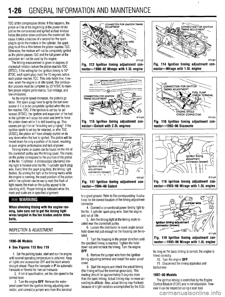
e See Figures 113 thru 119
1. Set the parking brake, start and run the engine
until normal operating temperature is obtained. Keep
all lights and accessories OFF and the front wheels
straight-ahead. Place the transaxle in
P for automatic
transaxle or Neutral for manual transaxle.
2. If not at specification, set the idle speed to the
correct level.
3. Turn the engine
OFF. Remove the water-
proof cover from the igmtion timing adjusting con-
nector, and connect a jumper wire from this terminal
Fig. 113 Ignition timing adjustment con-
nector-1990-92 Mirage with 1.5L engine
93151QM Fig. 115 Ignition timing adjustment con-
nectar-Galant with 2.OL engines
93151QO1 Fig. 117 Ignition timing adjustment con.
nectar-1994-96 Galant
to a good ground. Refer to the corresponding illustra-
tions for the correct location of the timing adjustment
connector.
4. Connect a conventional power timing light to
the No. 1 cylinder spark plug wire. Start the engine
and run at idle.
5. Aim the timing light at the timing scale lo-
cated near the crankshaft pulley.
6. Loosen the distributor or crank angle sensor
hold-down nut just enough so the housing can be ro-
tated.
7. Turn the housing in the proper direction until
the specified timing is reached. Tighten the hold-
down nut and recheck the timing. Turn the engine
OFF. 8. Remove the jumper wire from the ignition
timing adjusting terminal and install the water-proof
cover.
9. Start the engine and check the actual timing
(the timing without the terminal grounded). This
reading should be approximately 5 degrees more
than the basic timing. Actual timing may increase ac-
cording to altitude. Also, actual timing may fluctuate
because of slight variation accomplished by the ECU.
Fig. 114 Ignition timing adjustment con-
nectar-Miracle with 1.6L enaine
CHECK CONNECTOR 93151QO! Fig. 116 Ignition timing adjustment con.
nectar-1992-96 Oiamante
93151gOB Fig. 116 Ignition timing adjustment con-
nector-1993-96 Mirage with 1.5L engine
Fig. 119 Ignition timing adjustment con-
nector-1993-96 Mirage with 1.6L engine
As long as the basic timing is correct, the engine is
timed correctly.
10. Turn the engine
OFF. 11. Disconnect the timing apparatus and
tachometer.
1997-00 Models
The ignition timing is controlled by the Engine
Control Module (ECM) and is not adjustable. How-
ever it can be inspected using a scan tool.
Page 63 of 408
3-2 ENGINEANDENGINEOVERHAUL
REMOVAL &INSTALLATION
# See Figure 1
In the process of removing the engine, you will
come across a number of steps which call for the re-
moval of a separate component or system, such as
“disconnect the exhaust system” or “remove the radi-
ator.” In most instances, a detailed removal proce-
dure can be found elsewhere in this manual.
It is virtually impossible to list each individual
wire and hose which must be disconnected, simply
because so many different model and engrne combi-
nations have been manufactured Careful observation
and common sense are the best possible approaches
to any repair procedure.
Removal and installation of the engine can be
made easier if you follow these basic points:
l If you have to drain any of the fluids, use a
suitable container.
l Always tag any wires or hoses and, if possrble,
the components they came from before disconnect-
ing them.
l Because there are so many bolts and fasteners
involved, store and label the retainers from compo-
nents separately in muffin pans, jars or coffee cans.
This will prevent confusion during installatron.
l After unbolting the transmisston or transaxle,
always make sure it is properly supported.
l If it is necessary to disconnect the air condi-
tioning system, have this service performed by a
qualified technician using a recovery/recycling sta-
tion If the system does not have to be disconnected,
unbolt the compressor and set it aside.
l When unbolting the engine mounts, always
make sure the engine is properly supported. When
removing the engine, make sure that any lifting de-
vices are properly attached to the engine. It is recom-
mended that if your engine IS supplied with lifting
hooks, your lifting apparatus be attached to them.
l Lift the engine from its compartment slowly,
checking that no hoses, wires or other components
are still connected.
l After the engine is clear of the compartment,
place it on an engine stand or workbench.
l After the engine has been removed, you can
perform a partial or full teardown of the engine using
the procedures outlined in this manual.
1. Relieve fuel system pressure.
Observe all applicable safety precautions
when working around fuel. Whenever servic-
ing the fuel system, always work in a well
ventilated area. Do not allow fuel spray or
vapors to come in contact with a spark or
open flame. Keep a dry chemical fire extin-
guisher near the work area. Always keep fuel
in a container specifically designed for fuel
storage; also, always properly seal fuel con-
tainers to avoid the possibility of fire or ex-
plosion.
2. Disconnect the negative battery cable.
3. Remove the engine undercover if equipped. 4. Matchmark the hood and hinges and remove
the hood assembly.
5. Remove the air cleaner assembly and all ad-
joining air intake duct work.
6. Drain the engine coolant, remove the radiator
hoses, and remove the radiator assembly, coolant
reservoir, and intercooler, as equipped.
cooling system when hot; serious burns can
occur from the steam and hot coolant. Also,
when draining engine coolant, keep in mind
that cats and dogs are attracted to ethylene
glycol antifreeze and could drink any that is
left in an uncovered container or in puddles
on the ground. This will prove fatal in suffi-
cient quantities. Always drain coolant into a
sealable container. Coolant should be reused
unless it is contaminated or is several years
old.
7. Remove the transaxle and transfer case as
equipped.
8. Tag and detach the following electrical con-
nections:
l Accelerator cable l Heater hoses l Brake booster vacuum hose l Vacuum hoses l Fuel lines l Engine ground cables l Any applicable sensors l Coolant temperature and oil pressure send-
ing units
l Exhaust Gas Recirculation (EGR) tempera-
ture sensor
l Connection for the idle speed control mo-
tor
l Fuel injectors l Power transistor l Ignition coil and any applicable distributor
connections
l The connections for the alternator l Power steering pressure switch l A/C compressor l Refrigerant temperature switch l Condenser
9. Remove the air conditioner drive belt and the
air conditioning compressor. Leave the hoses at-
tached. Do not discharge the system. Place the com-
pressor aside and secure it using a suitable device.
10. Remove the power steering pump and place
the pump asrde and secure it using a surtable device.
11. Remove the exhaust manifold-to-exhaust
pipe nuts. Discard the gasket.
12. Install the engine hoist equipment and make
certain the attaching points on the engine are secure.
13. Raise the hoist enough to support the engine.
14. Remove the front and rear engine roll stop-
pers
15. Remove the left engine mount and support
Double check that all cables, hoses, harness
connectors, etc., are disconnected from the
engine.
16. Slowly lift the engine and remove it from the
vehicle.
To install:
17. Install the engine and secure all control
brackets and mounts.
18. Install the transaxle, and transfer case if
equipped.
19. The balance of the installation is the reverse
of removal with the addition of the following notes:
a. Use new clamps or O-rings to connect the
high pressure fuel lme and the fuel return line.
b. Use new gaskets to connect the exhaust
system to the engine.
c. Fill the engine with the proper amount of
engine oil and coolant.
d. Start the engine, allow it to reach normal
operating temperature.
e. Check for leaks.
f. Check the ignition timing and adjust if nec-
essary.
g. Road test the vehicle and check all fluid
levels and functions for proper operation.
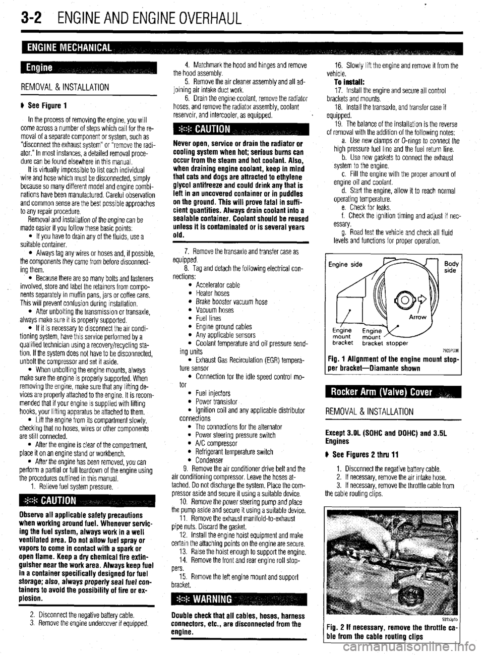
Fig. 1 Alignment of the engine mount stop-
oer bracket-Diamante shown
REMOVAL &INSTALLATION
Except 3.OL (SOHC and DOHC) and 3.5L
Engines
# See Figures 2 thru 11
1. Disconnect the negative battery cable.
2. If necessary, remove the air intake hose.
3. If necessary, remove the throttle cable from
the cable routing clips.
Fig. 2 If necessary, remove the throttle ca-
ble from the cable routing clips
Page 69 of 408
3-8' ENGINEANDENGINEOVERHAUL
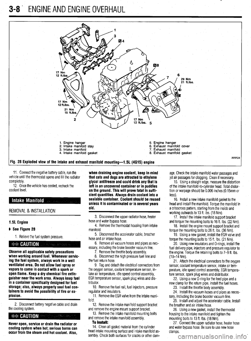
Nm ft.lbs.
1. Engine hanger 5. Engine hanger
2. Intake manifold stay 6. Exhaust manifold cover
3. intake manifold 7. Exhaust manifold
4. Intake manifold gasket 8. Exhaust manifold gasket
7923ffi38 :ig. 28 Exploded view of the intake and exhaust manifold mounting-l .5L (4615) engine
11. Connect the negative battery cable, run the ,. . . .
vemcie unnl me tnermostat opens ano till the radiator
completely. age. Check the intake manifold water passages and
jet air passages for clogging. Clean if necessary.
12. Once the vehicle has cooled, recheck the
coolant level.
REMOVAL &INSTALLATION when draining engine coolant, keep in mind
that cats and dogs are attracted to ethylene
glycol antifreeze and could drink any that is
left in an uncovered container or in puddles
on the ground. This will prove fatal In suffi-
cient quantities. Always drain coolant into a
sealable container. Coolant should be reused
unless it is contaminated or is several years
old.
15. Using a straight edge, measure the distortion
of the intake manifold-to-cylinder head. Total distor-
tion or warpage should be 0.006 inches (0.15mm or
less).
16. Install a new intake manifold gasket to the
head and install the manifold. Torque the manifold in
a crisscross pattern, starting from the inside and
working outwards to 13 ft. Ibs. (18 Nm).
17. Install the intake manifold support bracket
and torque the mounting bolts to 16 ft. Ibs. (22 Nm).
18. Install the engine mount support bracket and
torque the mounting bolts to 26 ft. Ibs. (36 Nm).
19. Using a new gasket, install the EGR valve and
torque the mounting bolts to 15 ft. Ibs. (21 Nm).
20. Using new insulators and O-rings, install the
fuel delivery pipe, injectors and pressure regulator to
the engine. Torque the retaining bolts to 7-9 ft. Ibs.
(10-14 Nm).
1.51 Engine
# See Figure 28
1. Relieve the fuel system pressure.
Observe all applicable safety precautions
when working around fuel. Whenever servic-
ing the fuel system, always work in a well
ventilated area. Do not allow fuel spray or
vapors to come in contact with a spark or
open flame. Keep a dry chemical fire extin-
guisher near the work area. Always keep fuel
in a container specifically designed for fuel
storage; also, always properly seal fuel con-
tainers to avoid the possibility of fire or ex-
plosion.
2. Disconnect battery negative cable and drain
the cooling system.
Never open, service or drain the radiator or
cooling system when hot; serious burns can
occur from the steam and hot coolant. Also,
3. Disconnect the upper radiator hose, heater
hose and water bypass hose.
4. Remove the thermostat housing from intake
manifold.
5. Disconnect the accelerator cable, breather
hose and air intake hose.
6. Remove all vacuum hoses and pipes as nec-
essary, including the brake booster vacuum line.
7. Remove the throttle body assembly.
8. Disconnect the high pressure fuel line and
the fuel return hose.
9. Tag and detach the electrical connectors from
the oxygen sensor, coolant temperature sensor, in-
take air temperature, idle speed control assembly,
EGR temperature sensor, spark plug wires and dis-
tributor.
10. Remove the fuel rail, fuel injectors, pressure
regulator and insulators.
11. Remove the EGR valve from the intake mani-
fold.
12. Remove the intake manifold support bracket
and remove the engine mount support bracket.
13. Remove the intake manifold mounting bolts
and remove the intake manifold assembly.
To Install: 14. Clean all gasket material from the cylinder
head intake mounting surface and intake manifold as-
sembly. Check both surfaces for cracks or other dam- 21. Attach the electrical connectors to the oxygen
sensor, coolant temperature sensor, intake air tem-
perature, idle speed control assembly, EGR tempera-
ture sensor, spark plug wires and distributor.
22. Using a new O-ring for the feed pipe and a
new clamp for the return pipe, install the fuel hoses.
23. Install the throttle body assembly.
24. Install the vacuum hoses and pipes as neces-
sary, including the brake booster vacuum line.
25. Install and adjust the accelerator cable. Install
the breather and air Intake hose.
26. Using a new gasket, install the thermostat
housing to the intake manifold and tighten the
mounting bolts to 13 ft. Ibs. (18 Nm).
27. Connect the upper radiator hose, heater hose
and water bypass hose. Be sure to use new hose
clamps.
Page 70 of 408
ENGINEANDENGINEOVERHAUL 3-9
28. Fill the system with coolant.
29. Connect the negative battery cable, run the
vehicle until the thermostat opens, fill the radiator
completely.
30. Check and adjust the idle speed and ignition
timing.
31. Once the vehicle has cooled, recheck the
coolant level.
1.8L Engine
) See Figures 29 and 30
I. Relieve the fuel system pressure.
Observe all applicable safety precautions
when working around fuel. Whenever servic-
ing the fuel system, always work in a well
ventilated area. Do not allow fuel spray or
vapors to come in contact with a spark or
open flame. Keep a dry chemical fire extin-
guisher near the work area. Always keep fuel
in a container specifically designed for fuel
storage; also, always properly seal fuel con-
tainers to avoid the possibility of fire or ex-
plosion.
2. Disconnect battery negative cable and drain
the cooling system.
Never open, service or drain the radiator or
cooling system when hot; serious burns can
occur from the steam and hot coolant. Also,
when draining engine coolant, keep in mind
that cats and dogs are attracted to ethylene
glycol antifreeze and could drink any that is
leff in an uncovered container or in puddles
on the ground. This will prove fatal in suffi-
cient quantities. Always drain coolant into a
sealable container. Coolant should be reused
unless it is contaminated or is several years
old.
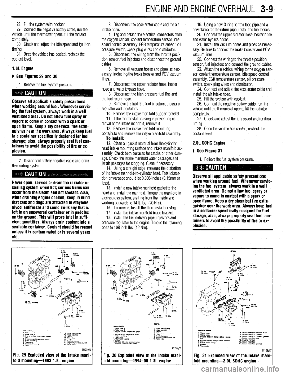
Fig. 29 Exploded view of the intake mani.
old mounting-1993 1.8L engine
3. Disconnect the accelerator cable and the air
intake hose.
4. Tag and detach the electrical connectors from
the oxygen sensor, coolant temperature sensor, idle
speed control assembly, EGR temperature sensor, oil
pressure switch, spark plug wires and distributor.
5. Disconnect the wiring from the throttle posi-
tion sensor, fuel Injectors and disconnect the ground
cables.
6. Remove all vacuum hoses and pipes as nec-
essary, including the brake booster and PCV vacuum
lines.
7. Disconnect the upper radiator hose, heater
hose and water bypass hose.
8. Disconnect the high pressure fuel line and
the fuel return hose.
9. Remove the fuel rail, fuel injectors, pressure
regulator and insulators.
10. Remove the intake manifold support bracket.
11. If the thermostat housing is preventing re-
moval of the Intake manifold, remove it.
12. Remove the intake manifold mounting
bolts/nuts and remove the intake manifold assembly.
To install: 13. Clean all gasket material from the cylinder
head intake mounting surface and intake manifold as-
sembly Check both surfaces for cracks or other dam-
age. Check the intake manifold water passages and
jet air passages for clogging. Clean if necessary.
14. Using a straight edge, measure the distortion
of the intake manifold-to-cylinder head. Total distor-
tion or warpage should be 0.006 inches (0.15mm or
less).
15. Install a new intake manifold gasket to the
head and install the manifold. Torque the manifold in
a crrsscross pattern, starting from the inside and
working outwards to 14 ft. Ibs. (20 Nm).
16. If removed, install the thermostat housing.
17. Install the Intake manifold brace bracket.
18. Install the fuel delivery pipe, injectors and
pressure regulator to the engine. Torque the retaining
bolts to 108 Inch Ibs. (12 Nm). 19. Using a new O-ring for the feed pipe and a
new clamp for the return pipe, install the fuel hoses,
20. Connect the upper radiator hose, heater hose
and water bypass hoses.
21. Install the vacuum hoses and pipes as neces-
sary. Be sure to connect the brake booster and PCV
vacuum lines
22. Connect the wiring to the throttle position
sensor, fuel injectors and connect the ground cables,
23. Attach the electrical wiring to the oxygen sen-
sor, coolant temperature sensor, Idle speed control
assembly, EGR temperature sensor, oil pressure
switch, spark plug wires and distributor.
24. Connect and adjust the accelerator cable and
install the air intake hose.
25. Fill the system with coolant.
26. Connect the negative battery cable, run the
vehicle until the thermostat opens, fill the radiator
completely.
27. Check and adjust the idle speed and ignition
timing.
28. Once the vehicle has cooled, recheck the
coolant level. 2.OL SOHC Engine
# See Figure 31
1. Relieve the fuel system pressure.
Observe all applicable safety precautions
when working around fuel. Whenever servic-
ing the fuel system, always work in a well
ventilated area. Do not allow fuel spray or
vapors to come in contact with a spark or
open flame. Keep a dry chemical fire extin-
guisher near the work area. Always keep fuel
in a container specifically designed for fuel
storage; also, always properly seal fuel con-
tainers to avoid the possibility of fire or ex-
plosion.
Fig. 30 Exploded view of the intake mani,
iold mounting-1994-00 1.8L engine Fig. 31 Exploded view of the intake mani
fold mounting-2.01 SOHC ermine
Page 71 of 408
3-10 ENGINEANDENGINEOVERHAUL
2. Disconnect the battery negative cable.
3. Drain the cooling system.
Never open, service or drain the radiator or
cooling system when hot; serious burns can
occur from the steam and hot coolant. Also,
when draining engine coolant, keep in mind
that cats and dogs are attracted to ethylene
glycol antifreeze and could drink any that is
left in an uncovered container or in puddles
on the ground. This will prove fatal in suffi-
cient quantities. Always drain coolant into a
sealable container. Coolant should be reused
unless it is contaminated or is several years
old.
4 Disconnect the accelerator cable and air in-
take hose.
5. Disconnect the upper radiator hose, heater
hose and water bypass hose.
6. Unplug the vacuum connection at the power
brake booster and the PCV valve if still connected.
Disconnect all remaining vacuum hoses and pipes as
necessary.
7. Disconnect the high pressure fuel line, fuel
return hose and remove throttle control cable brack-
ets
8. Tag and detach the electrical connectors from
the oxygen sensor, coolant temperature sensor,
therm0 switch, idle speed control assembly, EGR
temperature sensor, distributor, fuel injectors and
spark plug wires. Position the engine wiring harness
aside.
9. Matchmark the distributor housing to the in-
take manifold, and remove the distributor.
10. Remove the intake manifold bracket and the
engine hanger.
11. If the thermostat housing is preventing re-
moval of the intake manifold, remove it.
12. Remove the intake manifold mounting bolts
and remove the intake manifold assembly. Drsassem-
ble manifold from the Intake plenum on a work bench
as required
To install: 13. Clean all gasket material from the cylinder
head intake mounting surface and intake manifold as-
sembly. Check both surfaces for cracks or other dam-
age. Check the intake manifold water passages and
jet air passages for clogging. Clean if necessary.
14 Assemble the intake manifold assembly using
all new gaskets. Torque air intake plenum bolts to
11-14ff. Ibs. (15-19 Nm).
15. Install a new intake manifold gasket to the
head and install the manifold. Torque the manifold in
a crrsscross pattern, starting from the inside and
working outwards to 11-14 ff. Ibs. (15-19 Nm).
16. Install the fuel delivery pipe, injectors and
pressure regulator to the engine. Torque the retaining
bolts to 4 ft. Ibs (6 Nm).
17. install the thermostat housing, intake mani-
fold brace bracket, and engine hanger bracket.
18 Connect or install all hoses, cables and elec-
trical connectors that were removed or disconnected
during the removal procedure.
19. Align the distributor matchmarks and install
the distributor.
20. Fill the system with coolant,
21. Connect the negative battery cable, run the
vehicle until the thermostat opens, fill the radiator
completely. 22. Adjust the accelerator cable. Check and ad-
just the idle speed and ignition timing.
23. Once the vehicle has cooled, recheck the
coolant level.
1.6L and 2.OL DDHC Engines
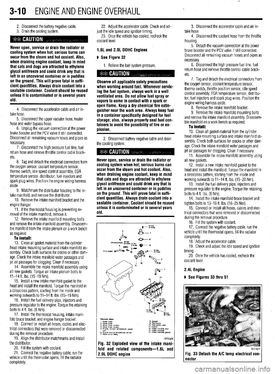
# See Figure 32
1. Relieve the fuel system pressure.
Observe all applicable safety precautions
when working around fuel. Whenever servic-
ing the fuel system, always work in a well
ventilated area. Do not allow fuel spray or
vapors to come in contact with a spark or
open flame. Keep a dry chemical fire extin-
guisher near the work area. Always keep fuel
in a container specifically designed for fuel
storage; also, always properly seal fuel con-
tainers to avoid the possibility of fire or ex-
ulosion.
2. Disconnect battery negative cable and drain
the cooling system.
Never open, service or drain the radiator or
cooling system when hot; serious burns can
occur from the steam and hot coolant. Also,
when draining engine coolant, keep in mind
that cats and dogs are attracted to ethylene
glycol antifreeze and could drink any that is
left in an uncovered container or in puddles
on the ground. This will prove fatal in suffi-
cient quantities. Always drain coolant into a
sealable container. Coolant should be reused
unless it is contaminated or is several years
old.
Fig. 32 Exploded view of the intake mani-
fold and related components-1.6L and
2.OL DDHC engine
3. Disconnect the accelerator cable and air in-
take hose.
4. Disconnect the coolant hose from the throttle
housing.
5. Detach the vacuum connection at the power
brake booster and the PCV valve If still connected.
Disconnect all remaining vacuum hoses and pipes as
necessary.
6. Drsconnect the high pressure fuel line, fuel
return hose and remove throttle control cable brack-
ets
7. Tag and detach the electrical connectors from
the oxygen sensor, coolant temperature sensor,
therm0 switch, throttle position sensor, rdle speed
control assembly, EGR temperature sensor, distribu-
tor, fuel injectors and spark plug wires. Position the
engine wiring harness aside.
8. Remove the intake manifold bracket.
9. Remove the intake mamfold mounting bolts
and remove the intake manifold assembly. Disassem-
ble manifold on a work bench as required.
To install:
10. Clean all gasket material from the cylinder
head intake mounting surface and intake manifold as-
sembly. Check both surfaces for cracks or other dam-
age. Check the intake manifold water passages and
jet air passages for clogging. Clean if necessary.
11. Assemble the Intake manifold assembly using
all new gaskets.
12. Install a new intake manifold gasket to the
head and install the manifold. Torque the manifold in
a crisscross pattern, starting from the inside and
working outwards to 11-14 ft. Ibs. (15-20 Nm).
13. Install the fuel delivery pipe, injectors and
pressure regulator to the engine. Torque the retaining
bolts to 4 ft. Ibs. (6 Nm).
14. Install the intake manifold brace bracket and
tighten bolts to 13-18 ft. Ibs. (18-25 Nm).
15. Connect or install all hoses, cables and elec-
trical connectors that were removed or disconnected
during the removal procedure.
16. Fill the system with coolant.
17. Connect the negative battery cable, run the
vehicle until the thermostat opens, fill the radiator
completely.
18. ‘Adjust the accelerator cable.
19. Check and adjust the idle speed and ignition
timing.
20. Once the vehicle has cooled, recheck the
coolant level.
2.4L Engine
) See Figures 33 thru 51
93153p37 Fig. 33 Detach the A/C temp electrical con- 1
Page 73 of 408
.
3-12 ENGINEANDENGINEOVERHAUL
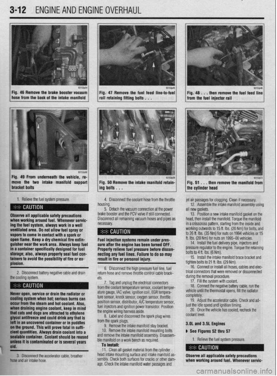
93153p54
1
L Fig. 46 Remove the brake booster vacuum
hose from the back of the intake manifold Fig 47 Remove the fuel feed line-to-fuel rail’retaini”g fitti”g bo,ts . . .
Fig. 49 From underneath the vehicle, re-
move the two intake manifold support
1. Relieve the fuel system pressure.
4. Disconnect the coolant hose from the throttle
Observe all applicable safety precautions
ing the fuel system, always work in a well when working around fuel. Whenever servic-
ventilated area. Do not allow fuel spray or - __.
vapors to come in contact with a spark or
._
open flame. Keep a dry chemical fire extin-
guisher near the work area. Always keep fuel
in a container specifically designed for fuel
storage; also, always properly seal fuel con-
tainers to avoid the possibility of fire or ex-
plosion.
2. Disconnect battery negative cable and drain
the cooling rtfctnm 93153p39 Fig. 50 Remove the intake manifold retain-
ing bolts . . .
h
n ousing.
5. Detach the vacuum connection at the power
b
rake booster and the PCV valve if still connected.
C lisconnect all remaining vacuum hoses and pipes as
ecessary. et air passages for clogging. Clean if necessary.
12. Assemble the intake manifold assembly using
III new gaskets.
13. Position a new intake manifold gasket on the
lead, then install the manifold. Torque the manifold
n a crisscross pattern, starting from the inside and
vorking outwards to 15 ft. Ibs. (20 Nm) for bolts, and
o 26 ft. Ibs. (35 Nm) for nuts on 1994 vehicles or 15
t. Ibs. (20 Nr$ for nuts on 1995-00 vehicles.
14. Install the fuel delivery pipe, injectors and
xessure regulator to the engine. Torque the retaining
)olts to 4 ft. Ibs. (6 Nm). Fuel injection systems remain under pres- f
sure after the engine has been turned OFF.
Properly relieve fuel pressure before discon-
necting any fuel lines. Failure to do so may [
result in fire or personal injury.
t 6. Disconnect the high pressure fuel line, fuel
return hose and remove throttle control cable brack- t
n+C.
cm. durino the removal orocedure. 15. Install the intake manifold brace bracket and
ighten bolts to 21 ft. Ibs. (29 Nm).
16. Connect or install all hoses, cables and elec-
rical connectors that were removed or disconnected
7. Tag and unplug the electrical connectors
from the coolant temperature sensor, coolant temper- 17: Fill the system with coolant.
18 Connect the negative battery cable, run the
, . : .., ,, ., , ,
,,,, ,. ,.
93153p73 Fig. 51 . . .
then remove the manifold from
the cylinder head
Ruver open, service or drain the radiator or
@Ming system when hot; serious burns can
II&ur from the steam and hot coolant. Also,
draining engine coolant, keep in mind ’
j “thiat cats and dogs are attracted to ethylene
. . . ..____ “..” 11_,1 -...... any that is
t uncovered container or in puddles
FE ol iha ground. This will prove fatal in suff i-
k ici?M quantities. Always drain coolant into a
$1 pealable container. Coolant should be reused
h’ uniass it is contaminated or is several years
j$O'd.
**w
ature gauge, IAC valve, ignition coil, EGR tempera-
ture sensor, knock sensor, oxygen sensor, throttle
position sensor, distributor, A/C temperature sensor,
fuel injectors and ignition power transistor. Position
the engine wiring harness aside.
8. Label and disconnect the spark plug wires
from the spark plugs.
9. Remove the intake manifold stay bracket.
IO. Remove the intake manifold mounting bolts
and remove the intake manifold assembly. Disassem-
ble manifold on a work bench as required.
Tan is”.+..ll. vemcle unrn me mermosrar opens, ml tne raalaror
completely.
19. Adjust the accelerator cable. Check and ad-
just the idle speed and ignition timing.
20. Once the vehicle has cooled, recheck the
coolant level.
3.OL and 3SL Engines
ti See Figures 52 thru 57
1. Relieve the fuel system pressure.
W.>. Clean all gasket material from the cylinder
!&S head intake mounting surface and intake manifold as-
fir!: 3. Disconnect the accelerator cable, breather
Observe all applicable safety precautions
El .;,
+w..” and air intake hose. sembly. Check both surfaces for cracks or other dam-
age. Check the intake manifold water passages and when working around fuel. Whenever servic-
Page 74 of 408
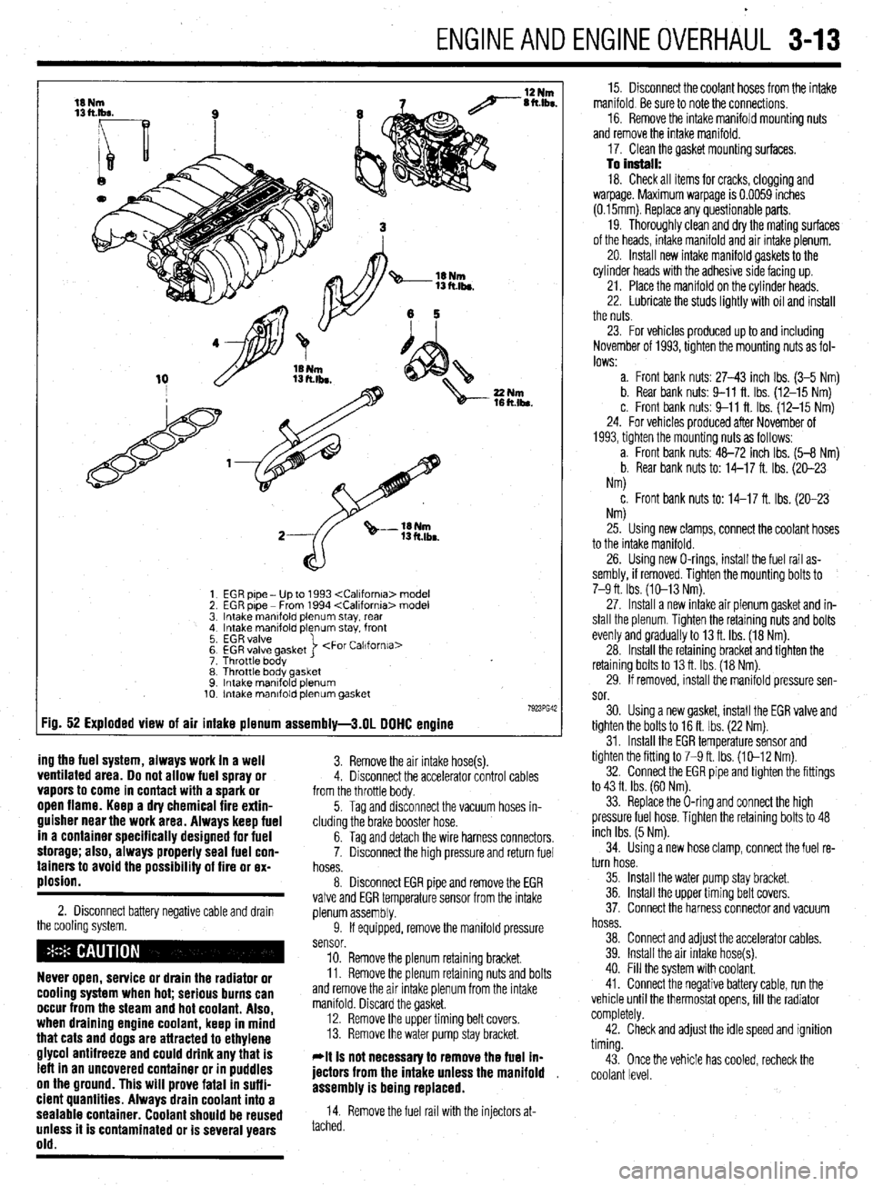
ENGINEANDENGINEOVERHAUL 3-13
EGR pipe - Up to 1993
EGR pipe - From 1994
Intake manlfold plenum stay, rear
Intake manifold plenum stay. front
EGR valve
EGR valve gasket
Throttle body >
Throttle body gasket
Intake mantfold plenum
Intake manifold plenum gasket
:ig. 52 Exploded view of air intake plenum assembly-3.01 DOHC engine
ing the fuel system, always work in a well
3. Remove the air intake hose(s). ventilated area. Do not allow fuel spray or 4. Disconnect the accelerator control cables vapors to come in contact with a spark or from the throttle body. open flame. Keep a dry chemical fire extin-
guisher near the work area. Always keep fuel
in a container specifically designed for fuel
storage; also, always properly seal fuel con-
tainers to avoid the possibility of fire or ex-
plosion.
2. Disconnect battery negative cable and drawn
the cooling system.
Never open, service or drain the radiator or
cooling system when hot; serious burns can
occur from the steam and hot coolant. Also,
when draining engine coolant, keep in mind
that cats and dogs are attracted to ethylene
glycol antifreeze and could drink any that is
left in an uncovered container or in puddles
on the ground. This will prove fatal in suffi-
cient quantities. Always drain coolant into a
sealable container. Coolant should be reused
unless it is contaminated or is several years
old.
5. Tag and disconnect the vacuum hoses in-
cluding the brake booster hose.
6. Tag and detach the wire harness connectors,
7. Disconnect the high pressure and return fuel
hoses.
8. Disconnect EGR pipe and remove the EGR
valve and EGR temperature sensor from the intake
plenum assembly.
9. If equipped, remove the manifold pressure
sensor.
10. Remove the plenum retaining bracket.
11. Remove the plenum retaining nuts and bolts
and remove the air intake plenum from the intake
manifold. Discard the gasket.
12. Remove the upper timing belt covers.
13. Remove the water pump stay bracket.
*It is not necessav to remove the fuel ln-
jectors from the intake unless the manifold ,
assembly is being replaced.
14. Remove the fuel rail with the injectors at-
tached. 15. Disconnect the coolant hoses from the intake
manifold. Be sure to note the connections.
16. Remove the intake manifold mounting nuts
and remove the intake manifold.
17. Clean the gasket mounting surfaces.
To install: 18. Check all items for cracks, clogging and
warpage. Maximum warpage is 0.0059 inches
(0.15mm). Replace any questionable parts.
19. Thoroughly clean and dry the mating surfaces
of the heads, intake manifold and air intake plenum.
20. Install new intake manifold gaskets to the
cylinder heads with the adhesive side facing up.
21. Place the manifold on the cylinder heads.
22. Lubricate the studs lightly with oil and install
the nuts.
23. For vehicles produced up to and including
November of 1993, tighten the mounting nuts as fol-
lows:
a. Front bank nuts: 27-43 inch Ibs. (3-5 Nm)
b. Rear bank nuts: 9-11 ft. Ibs. (12-15 Nm)
c. Front bank nuts: 9-11 ft. Ibs. (12-15 Nm)
24. For vehicles produced after November of
1993, tighten the mounting nuts as follows:
a. Front bank nuts: 48-72 inch Ibs. (5-8 Nm)
b. Rear bank nuts to: 14-17 ft. Ibs. (20-23
Nm)
c. Front bank nuts to: 14-17 ft. Ibs. (20-23
NM
25. Using new clamps, connect the coolant hoses
to the intake manifold.
26. Using new O-rings, install the fuel rail as-
sembly, if removed. Tighten the mounting bolts to
7-9 ft. Ibs. (10-13 Nm).
27. Install a new intake air plenum gasket and in-
stall the plenum. Tighten the retaining nuts and bolts
evenly and gradually to 13 ft. Ibs. (18 Nm).
28. Install the retaining bracket and tighten the
retaining bolts to 13 ft. Ibs. (18 Nm).
29. If removed, install the manifold pressure sen-
sor.
30. Using a new gasket, install the EGR valve and
tighten the bolts to 16 ft. Ibs. (22 Nm).
31. Install the EGR temperature sensor and
tighten the fitting to 7-9 ft. Ibs. (10-12 Nm).
32. Connect the EGR pipe and tighten the fittings
to 43 ft. Ibs. (60 Nm).
33. Replace the O-ring and connect the high
pressure fuel hose. Tighten the retaining bolts to 48
inch Ibs. (5 Nm).
34. Using a new hose clamp, connect the fuel re-
turn hose.
35. Install the water pump stay bracket.
36. Install the upper timing belt covers.
37. Connect the harness connector and vacuum
hoses.
38. Connect and adjust the accelerator cables.
39. Install the air intake hose(s).
40. Fill the system with coolant.
41. Connect the negative battery cable, run the
vehicle until the thermostat opens, fill the radiator
completely.
42. Check and adjust the idle speed and ignition
timing.
43. Once the vehicle has cooled, recheck the
coolant level.
Page 85 of 408
3-24 ENGINEANDENGINEOVERHAUL
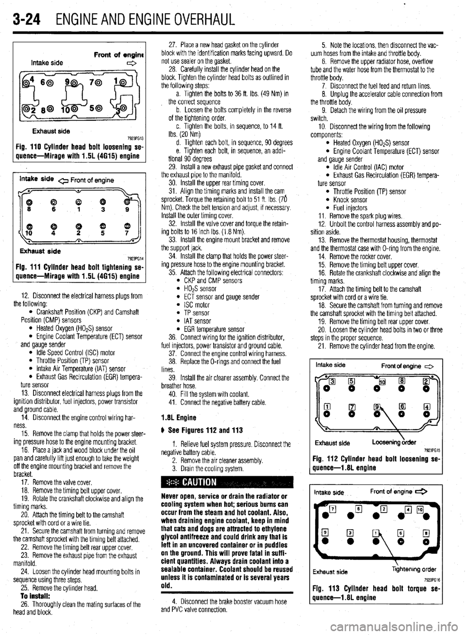
Intake side Front of engine
e
Exhaust side
7923PG13 Fig. 110 Cylinder head bolt loosening se-
uuence-Mirage with 1.5L (4615) ermine
inwe side 0 Front of engine
((9
Exhaust side
7923PG14 Fig. 111 Cyllnder head bolt tightening se-
quence-Mirage with 1.5L (4615) engine
12. Disconnect the electrical harness plugs from
the following:
l Crankshaft Position (CKP) and Camshaft
Position (CMP) sensors
l Heated Oxygen (HO*S) sensor l Engine Coolant Temperature (ECT) sensor
and gauge sender
l Idle Speed Control (ISC) motor l Throttle Position (TP) sensor l Intake Air Temperature (IAT) sensor l Exhaust Gas Recirculation (EGR) tempera-
ture sensor
13. Disconnect electrical harness plugs from the
ignition distributor, fuel injectors, power transistor
and ground cable.
14. Disconnect the engine control wiring har-
ness.
15. Remove the clamp that holds the power steer-
ing pressure hose to the engine mounting bracket.
16. Place a jack and wood block under the oil
pan and carefully lift just enough to take the weight
off the engine mounting bracket and remove the
bracket.
17. Remove the valve cover.
18. Remove the timing belt upper cover.
19. Rotate the crankshaft clockwise and align the
timing marks.
20. Attach the timing belt to the camshaft
sprocket with cord or a wire tie.
21. Secure the camshaft from turning and remove
the camshaft sprocket with the timing belt attached.
22. Remove the timing belt rear upper cover.
23. Remove the exhaust pipe from the exhaust
manifold.
24. Loosen the cylinder head mounting bolts in
sequence using three steps.
25. Remove the cylinder head.
To install:
26. Thoroughly clean the mating surfaces of the
head and block. 27. Place a new head gasket on the cylinder
block with the identification marks facing upward. Do
not use sealer on the gasket.
28. Carefully install the cylinder head on the
block. Tighten the cylinder head bolts as outlined in
the followlng steps:
a. Tighten the bolts to 36 ft. Ibs. (49 Nm) in
the correct sequence
b. Loosen the bolts completely in the reverse
of the tightening order,
c. Tighten the bolts, in sequence, to 14 ft.
Ibs. (20 Nm)
d. Tighten each bolt, in sequence, 90 degrees
e. Tighten each bolt, in sequence, an addi-
tional 90 degrees
29. Install a new exhaust pipe gasket and connect
the exhaust pipe to the manifold.
30. Install the upper rear timing cover.
31. Align the timing marks and install the cam
sprocket. Torque the retaining bolt to 51 ft. Ibs. (76
Nm). Check the belt tension and adjust, if necessary.
Install the outer timing cover.
32. Install the valve cover and torque the retain-
ing bolts to 16 inch Ibs. (1.8 Nm).
33. Install the engine mount bracket and remove
the support jack.
34. Install the clamp that holds the power steer-
ing pressure hose to the engine mounting bracket.
35. Attach the following electrical connectors:
l CKP and CMP sensors l HOPS sensor l ECT sensor and gauge sender l ISC motor l TP sensor l IAT sensor l EGR temperature sensor
36. Connect wiring for the ignition distributor,
fuel injectors, power transistor and ground cable.
37. Connect the engine control wiring harness.
38. Replace the O-rings and connect the fuel
lines.
39. Install the air cleaner assembly. Connect the
breather hose.
40. Fill the system with coolant.
41. Connect the negative battery cable.
1.8L Engine
# See Figures 112 and 113
1. Relieve fuel system pressure. Disconnect the
negative battery cable.
2. Remove the air cleaner assembly.
3. Drain the cooling system.
Never open, service or drain the radiator or
cooling system when hot; serious burns can
occur from the steam and hot coolant. Also,
when draining engine coolant, keep in mind
that cats and dogs are attracted to ethylene
glycol antifreeze and could drink any that is
lefl in an uncovered container or in puddles
on the ground. This will prove fatal in suffi-
cient quantities. Always drain coolant into a
sealable container. Coolant should be reused
unless it is contaminated or is several years
old.
4. Disconnect the brake booster vacuum hose
and PVC valve connection. 5. Note the locations, then disconnect the vac-
uum hoses from the intake and throttle body.
6. Remove the upper radiator hose, overflow
tube and the water hose from the thermostat to the
throttle body.
7. Disconnect the fuel feed and return lines.
8. Unplug the accelerator cable connection from
the throttle body.
9. Detach the wiring from the oil pressure
switch.
10, Disconnect the wiring from the following
components:
l Heated Oxygen (HO*S) sensor l Engine Coolant Temperature (ECT) sensor
and gauge sender
l Idle Air Control (IAC) motor l Exhaust Gas Recirculation (EGR) tempera-
ture sensor
l Throttle Position (TP) sensor l Knock sensor l Fuel injectors
11. Remove the spark plug wires.
12. Unbolt the control harness assembly and po-
sition aside.
13. Remove the thermostat housing, thermostat
and the thermostat case with O-ring from the engine.
14. Remove the rocker cover.
15. Remove the timing belt upper cover.
16. Rotate the crankshaft clockwise and align the
timing marks.
17. Attach the timing belt to the camshaft
sprocket with cord or a wire tie.
18. Secure the camshaft from turning and remove
the camshaft sprocket with the timing belt attached.
19. Remove the timing belt rear upper cover.
20. Loosen the cylinder head bolts in two or three
steps in the proper sequence.
21. Remove the cylinder head from the engine.
Intake side
Front of engine c=>
I
Exhaust side
Loosening &der 7923PG15 Fig. 112 Cylinder head bolt loosening se-
quence-l .8L engine
intake side Front of engine *
Exhaust side libhtenng order
Fig. 113 Cylinder head bolt torque se-
quence-l .8L engine
Page 86 of 408
ENGINEANDENGINEOVERHAUL 3-25
When removina the cvlinder head. take care
not to bend or iamag;! the plug guide. The
plug guide can not be replaced.
To install:
22. Thoroughly clean the mating surfaces of the
head and block.
23. Place a new head gasket on the cylinder
block with the identification marks facing upward. Do
not use sealer on the gasket.
24. Carefully install the cylinder head on the
block.
25. Measure the cylinder head bolts prior to in-
stallation Replace any that exceed 3.795 in.
(96.4mm)
26. Apply a small amount of engine oil to the
thread section of the bolt and install so the chamfer
of the washer faces upward.
27. Tighten the cylinder head bolts as follows:
a. In the proper tightening sequence, torque
bolts to 54 ft. Ibs. (75 Nm).
b. In the reverse order of the tightening se-
quence, fully loosen all bolts.
c In the proper trghtening sequence, torque
bolts to 14 ft. Ibs. (20 Nm).
d. In the proper tightening sequence, tighten
bolts 1/4 turn (90 degrees).
e. In the proper tightening sequence, tighten
bolts an additional 1/4 turn (90 degrees).
28. Install the camshaft sprocket and tighten the
bolt to 65 ft. Ibs (90 Nm), while holding the sprocket
in place using the appropriate wrench. Confirm
proper timing mark alignment.
29. Install the upper timing belt cover and rocker
cover. Torque the rocker cover bolts to 29 inch Ibs.
(3 Nm).
30. Loosen the water pipe mounting bolt for ease
of thermostat housing installation.
31. Apply a thin bead of sealant MD970389 or
equivalent, to the water tube connection on the ther-
mostat case.
32. Apply a small amount of water to the O-ring
of the water inlet pipe and press the thermostat case
assembly onto the water inlet pipe. Install the ther-
mostat case assembly mounting bolt tightening to 16
ff. Ibs. (22 Nm).
l ECT sensor and gauge sender l IAC motor 33. Tighten the water pipe mounting bolt.
34. Install the thermostat into the housing so the
jiggle valve is located at the top. Tighten the housing
bolts to 10 ft. Ibs (14 Nm).
35. Attach the wiring to the following compo-
nents:
l HO& sensor
l EGR temperature sensor l TP sensor l Knock sensor l Fuel injectors
36. Connect the upper radiator hose to the ther-
mostat housing.
37. Connect the accelerator cable connection to
the throttle body.
38. Connect the oil pressure switch.
39. Install the spark plug wires,
40. Connect the control harness assembly.
41. Replace the O-ring for the high pressure hose
and install a new clamp on the return hose and re-
connect the fuel lines. 42. Install the air intake hose. Connect the
breather hose and air cleaner case cover
43. Reconnect the brake booster and the PCV
vacuum hoses.
44. Fill the system with coolant.
45. Connect the negative battery cable
2.01 SOHC Engine
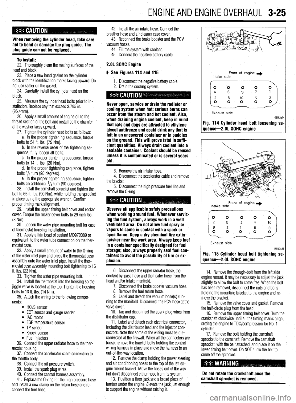
# See Figures 114 and 115
1. Disconnect the negative battery cable.
2. Drain the coolrng system.
Never open, service or drain the radiator or
cooling system when hot; serious burns can
occur from the steam and hot coolant. Also,
when draining engine coolant, keep in mind
that cats and dogs are attracted to ethylene
glycol antifreeze and could drink any that is
left in an uncovered container or in puddles
on the ground. This will prove fatal in suffi-
cient quantities. Always drain coolant into a
sealable container. Coolant should be reused
unless it is contaminated or is several years
old.
3. Remove the air intake hose.
4. Disconnect the accelerator cable and remove
the bracket.
5. Disconnect the high pressure fuel line and
remove the O-ring.
Observe all applicable safety precautions
when working around fuel. Whenever servic-
ing the fuel system, always work in a well
ventilated area. Do not allow fuel spray or
vapors to come in contact with a spark or
open flame. Keep a dry chemical fire extin-
guisher near the work area. Always keep fuel
in a container specifically designed for fuel
storage; also, always properly seal fuel con-
tainers to avoid the possibility of fire or ex-
plosion.
6. Disconnect the upper radiator hose, the
coolant by-pass hose and the heater hose from the
head and/or intake manifold.
7. Disconnect the brake booster vacuum hose.
8. Remove the fuel return hose.
9. Label and detach the vacuum hose(s) run-
ning to the manifold. Disconnect the PCV hose at the
valve cover.
10. Tag and disconnect the spark plug wires from
the drstnbutor cap
11. Label and detach each electrical connector,
including the distributor lead and the injector con-
nectors Note that some of the wiring must be drs-
connected at the firewall. When all the connectors are
loose, remove the bracket bolts holding the control
wiring harness rn place and move the harness to an
out-of-the-way location.
12. Remove the clamp holding the power steering
and air conditioning hoses to the top of the left en-
gine mount bracket. Move the hoses out of the way
but don’t drsconnect either hose from its system.
13. Position a floor lack and a broad piece of
lumber under the engine. Elevate the jack lust enough
to support the engine without raising it.
Front of engne I)
Intake side
~~
Exhaust side
93153~24 Fig. 114 Cylinder head bolt loosening se-
quence-2.01 SOHC engine
Front of engme I)
Intake side
Exhaust side
93153g25 Fig. 115 Cylinder head bolt tightening se-
quence-2.01 SDHC engine
14. Remove the through-bolt from the left side
engine mount. It may be necessary to adjust the jack
slightly to allow the bolt to come free When the bolt
has been removed, disconnect the nuts and bolts
holding the mounting bracket to the engine and re-
move the bracket
15. Remove the valve cover and gasket. Remove
the half-circle plug from the head.
16. Remove the upper timing belt cover. Turn the
crankshaft clockwise until all the timing marks align,
setting the engine to TDUcompression for No. 1
cylinder.
17. Remove the bolt holding the camshaft
sprocket to the camshaft. Remove the camshaft
sprocket, with the belt attached, and place it on the
lower timing belt cover. Do NOT allow the belt to
come off the sprocket
Do not rotate the crankshaft once the
camshaft sorocket is removed.
Page 87 of 408
3-26 ENGINEANDENGINEOVERHAUL
18. Remove the self-locking nuts and the small
retaining bolt holding the exhaust pipe to the bottom
of the exhaust manifold. Separate the pipe from the
manifold and remove the gasket.
19. Remove the bolts holding the support brace
to the bottom of the intake manifold.
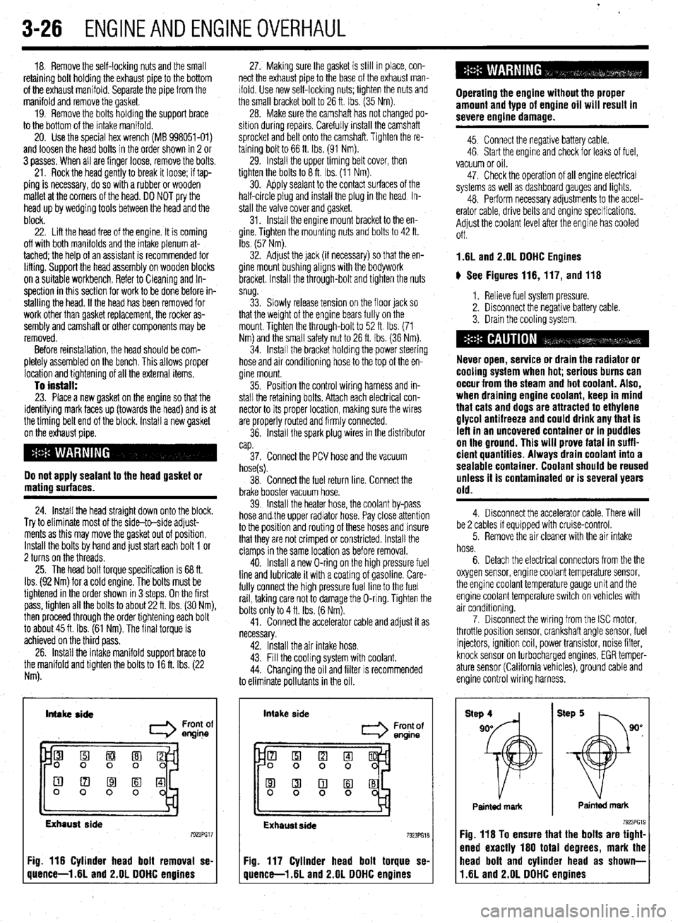
20. Use the special hex wrench (MB 998051-01)
and loosen the head bolts in the order shown in 2 or
3 passes. When all are finger loose, remove the bolts.
21. Rock the head gently to break it loose; if tap-
ping is necessary, do so with a rubber or wooden
mallet at the corners of the head. DO NOT pry the
head up by wedging tools between the head and the
block.
22. Lift the head free of the engine. It is coming
off with both manifolds and the intake plenum at-
tached; the help of an assistant is recommended for
lifting. Support the head assembly on wooden blocks
on a suitable workbench. Refer to Cleaning and In-
spection in this section for work to be done before in-
stalling the head. If the head has been removed for
work other than gasket replacement, the rocker as-
sembly and camshaft or other components may be
removed.
Before reinstallation, the head should be com-
pletely assembled on the bench. This allows proper
location and tightening of all the external items.
To install: 23. Place a new gasket on the engine so that the
identifying mark faces up (towards the head) and is at
the timing belt end of the block. Install a new gasket
on the exhaust pipe.
Do not apply sealant to the head gasket or
mating surfaces.
24. Install the head straight down onto the block.
Try to eliminate most of the side-to-side adjust-
ments as this may move the gasket out of position.
Install the bolts by hand and just start each bolt 1 or
2 turns on the threads.
25. The head bolt torque specification is 68 ft.
Ibs. (92 Nm) for a cold engine. The bolts must be
tightened in the order shown in 3 steps. On the first
pass, tighten all the bolts to about 22 ft. Ibs. (30 Nm),
then proceed through the order tightening each bolt
to about 45 ft. Ibs. (61 Nm). The final torque is
achieved on the third pass.
26. Install the intake manifold support brace to
the manifold and tighten the bolts to 16 ft. Ibs. (22
Nm). 27. Making sure the gasket is still in place, con-
nect the exhaust pipe to the base of the exhaust man-
ifold. Use new self-locking nuts; tighten the nuts and
the small bracket bolt to 26 ft. Ibs. (35 Nm).
28. Make sure the camshaft has not changed po-
sition during repalrs. Carefully install the camshaft
sprocket and belt onto the camshaft. Tighten the re-
taining bolt to 66 ft. Ibs. (91 Nm).
29. Install the upper timing belt cover, then
tighten the bolts to 8 ft. Ibs. (11 Nm).
30. Apply sealant to the contact surfaces of the
half-circle plug and install the plug in the head In-
stall the valve cover and gasket.
31. Install the engine mount bracket to the en-
gine. Tighten the mounting nuts and bolts to 42 ft.
Ibs. (57 Nm).
32. Adjust the jack (if necessary) so that the en-
gine mount bushing aligns with the bodywork
bracket. Install the through-bolt and tighten the nuts
snug.
33. Slowly release tension on the floor jack so
that the weight of the engine bears fully on the
mount. Tighten the through-bolt to 52 ft. Ibs. (71
Nm) and the small safety nut to 26 ft. tbs. (36 Nm).
34. Install the bracket holding the power steering
hose and air conditioning hose to the top of the en-
gine mount.
35. Position the control wiring harness and in-
stall the retaining bolts. Attach each electrical con-
nector to its proper location, making sure the wires
are properly routed and firmly connected.
36. Install the spark plug wires in the distributor
cap.
37. Connect the PCV hose and the vacuum
hose(s).
38. Connect the fuel return line. Connect the
brake booster vacuum hose.
39. Install the heater hose, the coolant by-pass
hose and.the upper radiator hose. Pay close attention
to the position and routing of these hoses and insure
that they are not crimped or constricted. Install the
clamps in the same location as before removal.
40. Install a new O-ring on the high pressure fuel
line and lubricate it with a coating of gasoline. Care-
fully connect the high pressure fuel line to the fuel
rail, taking care not to damage the O-ring. Tighten the
bolts only to 4 ft. Ibs. (6 Nm).
41. Connect the accelerator cable and adjust it as
necessary.
42. Install the air intake hose.
43. Fill the cooling system with coolant.
44. Changing the oil and filter is recommended
to eliminate pollutants in the oil.
Intake side
I Front of
engine
Exhaust side
Fig. 116 Cylinder head bolt removal se-
quence-l .6L and 2.OL DDHC engines intake
side
Front of
entine
Exhaust side 7923PG18
Fig. 117 Cylinder head bolt torque se-
quence-l .6L and 2.OL DDHC engines Operating the engine without the proper
amount and type of engine oil will result in
severe engine damage.
45. Connect the negative battery cable.
46. Start the engine and check for leaks of fuel,
vacuum or oil.
47. Check the operation of all engine electrical
systems as well as dashboard gauges and lights.
48. Perform necessary adjustments to the accel-
erator cable, drive belts and engine specifications.
Adjust the coolant level after the engine has cooled
Off.
1.6L and 2.OL DDHC Engines
ti See Figures 116,117, and 116
1. Relieve fuel system pressure.
2. Disconnect the negative battery cable.
3. Drain the cooling system.
Never open, service or drain the radiator or
cooling system when hot; serious burns can
occur from the steam and hot coolant. Also,
when draining engine coolant, keep in mind
that cats and dogs are attracted to ethylene
glycol antifreeze and could drink any that is
left in an uncovered container or in puddles
on the ground. This will prove fatal in suffi-
cient quantities. Always drain coolant into a
sealable container. Coolant should be reused
unless it is contaminated or is several years
old.
4. Disconnect the accelerator cable. There will
be 2 cables if equipped with cruise-control.
5. Remove the air cleaner with the air intake
hose.
6. Detach the electrical connectors from the the
oxygen sensor, engine coolant temperature sensor,
the engine coolant temperature gauge unit and the
engine coolant temperature switch on vehicles with
air conditioning.
7. Disconnect the wiring from the ISC motor,
throttle position sensor, crankshaft angle sensor, fuel
injectors, ignition coil, power transistor, noise filter,
knock sensor on turbocharged engines, EGR temper-
ature sensor (California vehicles), ground cable and
engine control wiring harness.
Painted mark Painted mark
Fig. 116 To ensure that the bolts are tight-
ened exactly 160 total degrees, mark the
11.6L and 2.OL DDHC engines head bolt and cylinder head as shown-