fog light MITSUBISHI DIAMANTE 1900 Repair Manual
[x] Cancel search | Manufacturer: MITSUBISHI, Model Year: 1900, Model line: DIAMANTE, Model: MITSUBISHI DIAMANTE 1900Pages: 408, PDF Size: 71.03 MB
Page 229 of 408

6-26 CHASSIS ELECTRICAL
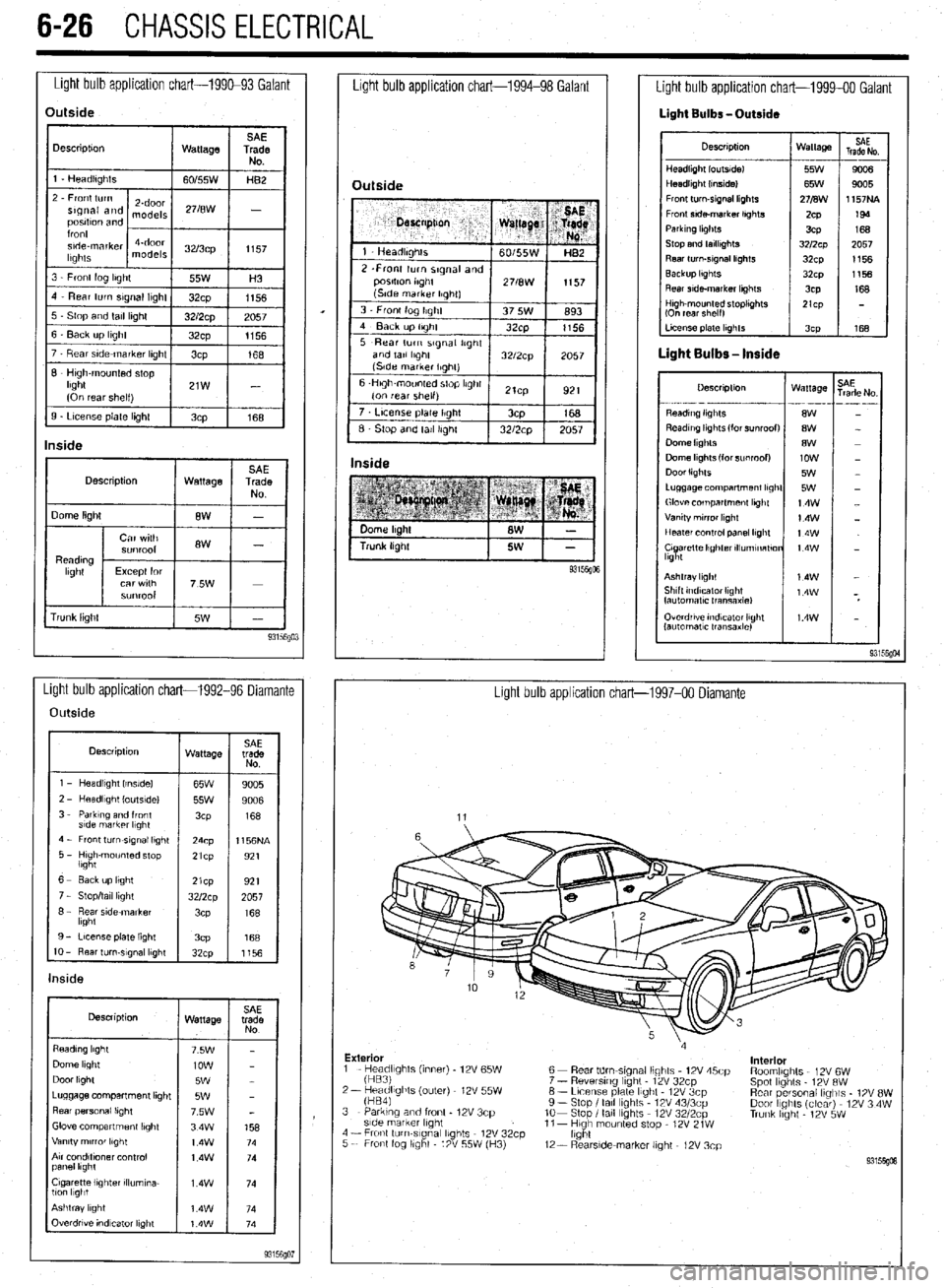
Light bulb application chart-199&93 Galant
Light bulb application chart-1994-98 Galant
Description
1 Wattage 1
rrunk lrght Overdrwe rndvzator light
lautomatlc transaxle)
Light bulb application chart-1992-96 Diamante
Light bulb application chart-1997-00 Diamante
Outside
Description
wattage SAE
trade
NO
1 - Headlrght Irnslde)
65W
9005
l----if
2 - HeadlIght loutsldel
55w 9006
3 - Parktng and front
3cP 168
s!de markrr l,ght
4 - Front turn-srgnal light
24cp 1156NA
5 - Hugh-mounted stop
lbght 21cp
921
1 6- Eackuplrght
I 1921 21cp
7 - Stop/tall light
8 - Rear side marker
lkght
9 - License plate light
3cP 168
IO - Rear turn-slgnal lkght
32cp
1156
Description
Wattage
Dome light
Door light
Luggage compartment lrght
Rear personal lrght
Glove compartment lbght
Vanity mrrror lkght
Arr condltfoner control
panel lkght
Cigarette lighter rllumrna-
llcm l1gbt
Outside
7 t License plate Ilght / 3cp
168
6 Stop and tall Irghl 1 32/2cp 1 2057 I
Inside
Light bulb application chart-1999-00 Galant
Light Bulbs -Outside
Descrrptron Wattage
HeadlIght loutsldel 55W
Headlight (Inside1 65W
Front turn-srgnal lkghts 271B\1\1
Fronr srde-marker lrghts
ZCP
Parkrng hghts
3CP
Stop and tarllrghts 3212~~
Rear turn-srgnal lrghts
32cp
Backup lkghts
32~x1
Rear srde-marker lkghts
3CP SAE
Trade No
---
90a
9005
1157NA
199
168
2057
1156
1156
168
LI- 168
Descrrptron Wattage
- . ..-- -- --_ .---
8W
8W
8W
low
5W
5W
14w
14W
t4w
t4w
Ashtray light
Shtft tndrcaror Ilght
fautomatlc Iransaxlel
Exterior
interior
1 - He;;;fghts (inner) - 12V 65W
2- keadlights (outer) 12V 55W
fHB41 6 - Rear tdm-stgnal lights 12V 45cp
7 - Reversrng light - 12V 32cp
6 - Lrcense plate light 12V 3cp
9 - Stop I tall lights 12V 43/3cp
lo- Stop I tall Ibghts 12V 3212~~
11- Hugh mounted stop - 12V 21W
light RoomlIghts 12V 6W
Spot lights 12V RW
Rear personal lrglils - 1% 8W
Door IIghts (clear) 12V 3 4W
Trunk hght - 12V 5W 3 - Parking and front - 12V 3cp
side marker lrght
4 - Fronl turn-slgnal lights 12V 32cp
5 - Front fog llghl 12V 55W (H3)
12- RearsIde-marker light - 12V 3cp
Page 232 of 408

CHASSIS ELECTRlCiL 6-29
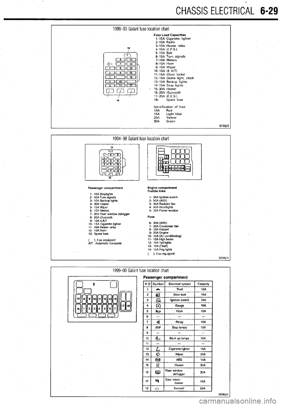
1990-93 Galant fuse location chart Fuse Load Capacities
l-15A Cigarette hghter
Z-10A Radm
3-10A Heater relay
4-10A (E P S.)
5-10A Belt
6-10A Turn signals
7-10A Meters
6-10A Horn
9-15A Wiper
lo-10A (4 A/T)
ll-15A (Door locks)
12-10A Dome hght, clock
13-10A Backup hghts
14-15A Stop hghts
15-30A Heater
16m20A (Sunroof)
17-20A (ECS)
1% spare fuse
ldentlfxation of fuse
10A Red
15A Light blue
20A Yellow
30A Green
93156g13
1994-98 Galant fuse location chart
Passenger compartment
1. 15A StoplIghts
2- 10A Turn signals
3- 1 OA Backup Itghts
4. 30A Heater
5. i5A Wiper
6- IOA Meters
7. 30A Rear wndow defogger
;: fo& fl$oof)
IO- 15A Cagaretle lighler
11. 10A Heater relay
12. IOA Horn
13. Spare fuse
( ): II so equipped
A!T Automallc transaxle Engine compartment
Fusible links
I- 30A Ignition swlch
2. 50A (ABS)
3. 30A Radiator fan
4. 40A Headkghts
5. 30A Power wndow
Fuse
6- 30A (ABS)
7. 30A Condenser fan
6. 10A Hazard
9. 20A Engine
10. 10A (Au conditioning)
11. 10AHigh beam
12. 10ATall lkghts
13. 10A (Theft)
14. i5A Fog lkghls
( ): If so equipped
93156g14
1999-00 Galant fuse location chart
Page 375 of 408

BODYANDTRIM IO-7
1. Ashtray
2 cenrer DaneI
3. Sunglass pocket
4 Side panel assembly
5 Knee protector assembly (L
6 Hood lock release handle
7 Column cover. lower
8 Column cover. upper
9 Radio
10 Striker
11. Glove box assembly
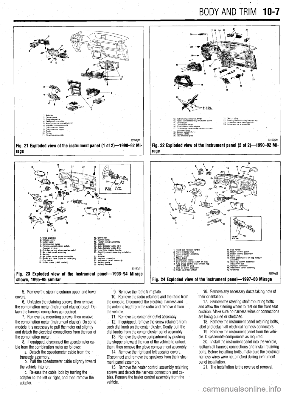
Fig. 21 Exploded view of the instrument panel (1 of 2)-1990-92 Mi-
rage
1. Knee pmtector
2. Column cover
3. Meter bezel
4. Combination meter
5. Remote control mirror switch.
rhsostat or plug
6. Coin box or rear wper washer switch
7. Aw outlet panel assembly
6. Ashtray
0. Air outlet center panel assembly
10. Radio and tape player or radio plug
11. Cup holder
12. Under COW (1993 models) 14. Comer panel
15. Heater control assembly %.
16. Speaker
17. Side defroster grille (RH)
16. Side defroster grille (LH)
19. Hood lock release handle
20. Ee$ng column assembly mstallation
21. Adapter
22 Harness oonnector
23. Instrument panel assembly
24. Ashtray panel
25. Ashtray bracket
9315og21 Fig. 23 Exploded view of the instrument panel-1993-94 Mirage
shown, 1995-95 similar
5. Remove the steering column upper and lower
covers.
6. Unfasten the retaining screws, then remove
the combination meter (instrument cluster) bezel. De-
tach the harness connectors as required.
7. Remove the mounting screws, then remove
the combination meter (instrument cluster). On some
models it is necessary to pull the meter out slightly
and detach the electrical connections from the rear of
the combination meter.
8. If equipped, disconnect the speedometer ca-
ble from the combination meter as follows:
a. Detach the speedometer cable from the
transaxle assembly.
b. Pull the speedometer cable slightly toward
the vehicle interior.
c. Release the cable lock by turning the
adapter to the left or right, and then remove the
adapter.
18
S-14Nm
7-lOh.lbs.
12 ln~v~rnent panel cover. lower
13 Hearer control assembly w,tallatlon screw
14 Meter bezel
15 Combination meter
16 Speedometer cable adapter
17 Comblnawn meterwr~ng harness connec-
. to1 co”“ectlo”s
16 Speaker amlsh (R H )
19 Speaker RHI e
20 S\de defroster grllla 21 Clock 01 plug
22 Steering shaft mount,ng bolt and nut
23 Ins!rument panel mounting bolts
24 Instrument panel assembly
9315og20 Fig. 22 Exploded view of the instrument panel (2 of 2)-1990-92 Mi-
rage
Fig. 24
1. Hood lock release handle
2. Knee protactor plug
3. Knee protector assembly
4 Column cover
5. Meter bezel
6. Combination meter
7. Door mrror control swich or plug
6. Auto-CNISO control mam swtch. fog
hght swtch M plug
0. Stde av outlet assembly
10 Radio and tape player 11. Cup holder
12. Heater control panel
13. Heater control assembly
14. Glove box
15 Front passenger’s 81, bag module
assembly
16. Steerq column assembly
lnstallatlon bon
17. Harness connector
16. Instrument panel assembly
19 Grommet
Exploded view of the instrument panel-l 997-00 Mirage
9. Remove the radio trim plate.
IO. Remove the radio retainers and the radio from
the console. Disconnect the electrical harness and
the antenna lead from the radio and remove it from
the vehicle.
11. Remove the center air outlet assembly.
12. If equipped, remove the screw retainers from
each dial knob on the center cluster. Gently pull the
dial knobs from the center cluster panel assembly.
13. Remove the glove compartment by pushing
the stoppers toward the rear of the vehicle to unlock
them, then remove the glove compartment assembly.
14. Remove the right and left speaker covers.
Disconnect and remove the speakers from the instru-
ment panel assembly.
15. Remove the heater control assembly retaining
screws and detach the harness connectors and ca-
bles. Remove the heater control assembly from the
vehicle. , 16. Remove any necessary ducts taking note of
their orientation,
17. Remove the steering shaft mounting bolts
and allow the steering wheel to rest on the front seat
cushion, Make sure no harness wires or connections
are being pulled or stretched.
18. Remove the instrument panel retaining bolts,
label and detach all electrical harness connectors.
19. Remove the instrument panel from the vehi-
cle. Disassemble components as required.
20. Install the instrument panel into the vehicle,
reattach all harness connections and install retaining
bolts. Before installing bolts, make sure the electrical
harness wires were not pinched during instrument
panel installation.
21. The installation is the reverse of removal.