width MITSUBISHI DIAMANTE 1900 Repair Manual
[x] Cancel search | Manufacturer: MITSUBISHI, Model Year: 1900, Model line: DIAMANTE, Model: MITSUBISHI DIAMANTE 1900Pages: 408, PDF Size: 71.03 MB
Page 98 of 408
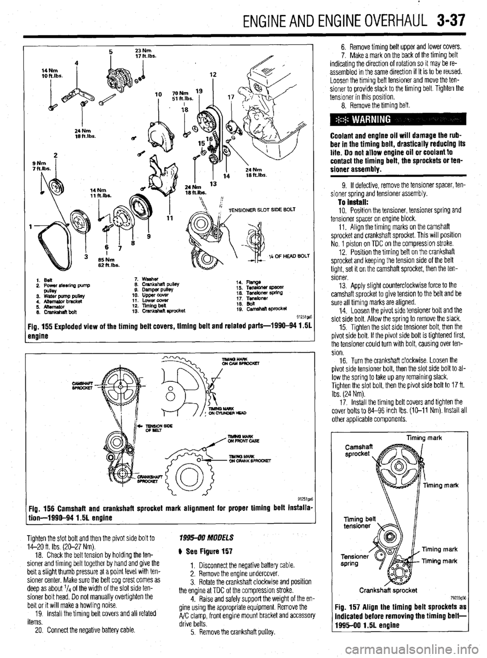
ENGINEANDENGINEOVERHAUL 3-37
1. Ben
2. Power4teerlna Dump 7. washer
8. Crankshaft pullet
9. Damper pulls
10. upper ccwer
11. Lowercowr
12. llmingbeil
13. crsnkshat? E#ocket 14. Flsnge
i 5. Tensbner spacer
16. Tef~kner WkW
1; Tgibnrr
19: camehan sprocket
91251ga
Fig. 155 Exploded view of the timing belt covers, timing belt and related parts-1990-94 1.51
engine
Fig. 156 Camshaft and crankshaft sprocket mark alignment for proper timing belt installa-
tion-1990-94 1.51 engine
Tighten the slot bolt and then the pivot side bolt to
14-20 ft. Ibs. (20-27 Nm).
18. Check the belt tension by holding the ten-
sioner and timing belt together by hand and give the
belt a slight thumb pressure at a point level with ten-
sioner center. Make sure the belt cog crest comes as
deep as about l/4 of the width of the slot side ten-
sioner bolt head. Do not manually overtighten the
belt or it will make a howling noise.
19. Install the timing belt covers and all related
items. 1995-00 MOOFLS
) See Figure 157
1. Disconnect the negative battery cable.
2. Remove the engine undercover.
3. Rotate the crankshaft clockwlse and position
the engine at TDC of the compression stroke.
4. Raise and safely support the weight of the en-
gine using the appropriate equipment. Remove the
A/C clamp, front engine mount bracket and accessory
drive belts.
20. Connect the negative battery cable.
5. Remove the crankshaft pulley. 6. Remove timing belt upper and lower covers.
7. Make a mark on the back of the timing belt
indicating the direction of rotation so it may be re-
assembled in the same direction if it is to be reused.
Loosen the timing belt tensioner and move the ten-
sioner to provide slack to the timing belt. Tighten the
tensioner in this position.
8. Remove the timing belt.
Coolant and engine oil will damage the rub-
ber in the timing belt, drastically reducing its
life. Do not allow engine oil or coolant to
contact the timing belt, the sprockets or ten-
sioner assembly.
9. If defective, remove the tensioner spacer, ten-
sioner spring and tensioner assembly.
To install: 10. Position the tensioner, tensioner spring and
tensioner spacer on engine block.
11. Align the timing marks on the camshaft
sprocket and crankshaft sprocket. This will position
No. 1 piston on TDC on the compression stroke.
12. Position the timing belt on the crankshaft
sprocket and keeping the tension side of the belt
tight, set it on the camshaft sprocket, then the ten-
sioner.
13. Apply slight counterclockwise force to the
camshaft sprocket to give tension to the belt and be
sure all timing marks are aligned.
14. Loosen the pivot side tensioner bolt and the
slot side bolt. Allow the spring to remove the slack.
15. Tighten the slot side tensioner bolt, then the
pivot side bolt. If the pivot side bolt is tightened first,
the tensioner could turn with bolt, causing over ten-
sion.
16. Turn the crankshaft clockwise. Loosen the
pivot side tensioner bolt, then the slot side bolt to al-
low the spring to take up any remaining slack.
Tighten the slot bolt, then the pivot side bolt to 17 ft.
Ibs. (24 Nm).
17. Install the timing belt covers and tighten the
cover bolts to 84-96 inch Ibs. (E-11 Nm). Install all
other applicable components.
liming mark
ming mark
Timing mark
Timing mark
Crankshaft sprocket
79235g5t Fig. 157 Align the timing belt sprockets as
indicated before removing the timing belt-
1995-00 1.51 engine
Page 115 of 408
3-54 ENGINEANDENGINEOVERHALJL
from the, access may be possible (though a little
awkward) to measure the camshaft lobes using a mi-
crometer
In any case, two measurements are necessary for
each lobe. Measurement Y or the total LOBE HEIGHT
and measurement X or the total LOBE WIDTH. To
find the lobe lift, you simply subtract X from Y (sub-
tract the width from the height).
Note each measurement, then make your calcula-
tion to determine the lift. Note the final results and re-
peat the process on the remaining camshaft lobes.
Finally, you should compare your results to the spec-
ifications charts and decide if a new camshaft is in
your future.
REMOVAL &INSTALLATION
2.OL and 2.4L Engines
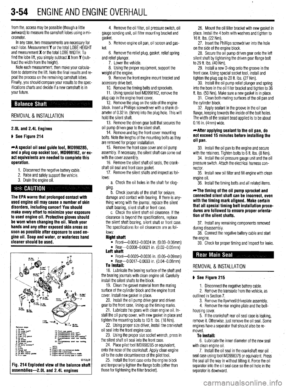
p See Figure 214
*A special oil seal guide tool, 18998285,
and a plug cap socket tool, MD998182, or ex-
act equivalents are needed to complete this
operation.
1. Disconnect the negative battery cable.
2. Raise and safely support the vehicle.
3. Drain the engine oil.
The EPA warns that prolonged contact with
used engine oil may cause a number of skin
disorders, including cancer! You should
make every effort to minimize your exposure
to used engine oil. Protective gloves should
be worn when changing the oil. Wash your
hands and any other exposed skin areas as
soon as possible after exposure to used en-
gine oil. Soap and water, or waterless hand
cleaner should be used.
93153g3
:ig. 214 Exploded view of the balance shaf
assemblies-2.01 and 2.4L enoines
4. Remove the oil filter, oil pressure switch, oil
gauge sending unit, oil filter mounting bracket and
gasket.
5. Remove engine oil pan, oil screen and gas-
ket.
6. Remove the relief plug, gasket, relief spring
and relref plunger.
7. Lower the vehicle.
8. Using the proper equipment, support the
weight of the engine.
9. Remove the front engine mount bracket and
accessory drive belt,
10. Remove the timing belts and sprockets.
11. Using special tool MD998162, remove the
plug cap in the engine front cover.
12. Remove the plug on the side of the engine
block. Insert a Phillips screwdriver with a shank di-
ameter of 0.32 in. (8mm) into the plug hole. This will
hold the silent shaft.
13. Remove the driven gear bolt that secures the
oil pump driven gear to the silent shaft.
14. Remove and tag the front cover mounting
bolts. Note the lengths of the mounting bolts as they
are removed for proper installation.
15. Remove the front case cover and oil pump
assembly. If necessary, the silent shaft can come out
with the cover assembly.
16. Remove the silent shaft oil seals, the crank-
shaft oil seal and front case gasket
17. Remove the silent shafts and inspect as fol-
lows:
a. Check the oil holes in the shaft for clog-
ging.
b. Check journals of the shaft for seizure,
damage and contact with bearing. If there is any-
thing wrong with the journal, replace the silent
shaft bearing, silent shaft or front case.
c. Check the silent shaft oil clearance. If the
clearance is beyond the specifications, replace
the silent shaft bearing, silent shaft or front case.
The specifications for oil clearances are as fol-
lows
Right shaft l Front-0.0012-0.0024 in. (0.030.06mml l Rear+0.0008-0.0021 in. (6.02-O 05mm) Left shaft l Front-0.002&0.0036 in. (0.05-0.09mm) l Rear-O.0017-O.0033 in. (0.04-0.08mm) To install: 18. Lubricate the bearing surface of the shaft and
the bearing journals with clean engine oil. Carefully
install the silent shafts to the block.
19. Clean the gasket material from the mating
surface of the cylinder block and the engine front
cover. Install new gasket in place.
20. Install the oil pump drive gear and driven
gear to the front case, lining up the timing marks.
21. Lubricate the gears with clean engine oil. In-
stall the oil pump cover, with new gasket in place and
tighten the mounting bolts to 13 ft. Ibs. (18 Nm).
22. Using proper size driver, install the crankshaft
oil seal into the front engine case.
23. Using the proper size socket wrench, press in
the silent shaft oil seal into the front case.
24. Place pilot tool MD998285 or equivalent,
onto the nose of the crankshaft. Apply clean engine
oil to the outer circumference of the pilot tool.
25. Install the front case onto the engine block
and temporarily tighten the flange bolts (other than
those for tightening the filter bracket). 26. Mount the oil filter bracket with new gasket in
place. Install the 4 bolts with washers and tighten to
16 ft Ibs. (22 Nm).
27. Insert the Phillips screwdriver into the hole
on the side of the engine block.
28. Secure the oil pump driven gear onto the left
silent shaft by tightening the driven gear flange bolt
to 29 ft. Ibs. (40 Nm).
29. Install a new O-ring onto the groove in the
front case. Using special socket tool, install and
tighten the plug cap to 20 ft. Ibs (27 Nm).
30. Install the oil pump relief plunger and spring
into the bore in the oil filter bracket and tighten to 36
ft. Ibs. (50 Nm). Make sure a new gasket is in place.
31. Clean both mating surfaces of the oil pan and
the cylinder block.
32. Apply sealant in the groove in the oil pan
flange, keeping towards the inside of the bolt holes.
The width of the sealant bead applied is to be about
0.16 in. (4mm) wide.
*After applying sealant to the oil pan, do
not exceed 15 minutes before installing the
oil pan.
33. Install the oil pan to the engine and secure
with the retainers. Tighten bolts to 6 ft. Ibs. (8 Nm).
34. Install the oil pressure gauge unit and the oil
pressure switch. Attach the electrical harness con-
nector
35. Install new oil filter and fill engine with clean
engine oil.
36. Install the timing belts and all related items,
*The timing of the oil pump sprocket and
connected silent shaft can be incorrect, even
with the timing mark aligned. Make certain
that all special timing belt installation proce-
dures are followed to ensure proper orienta-
tion of the silent shafts.
37. Install any remaining components removed
during disassembly.
38. Connect the negative battery cable and start
the engine.
39. Check for proper timing and inspect for leaks.
REMOVAL &INSTALLATION
p See Figure 215
1. Disconnect the negative battery cable.
2. Remove the transaxle from the vehicle, as
outlined in Section 7.
3. Remove the flywheel/driveplate assembly.
4. Remove the rear engine plate and the bell-
housing cover.
5. If the crankshaft rear oil seal case is leaking,
remove it. Otherwise, just remove the oil seal. Some
engines have a separator that should also be re-
moved.
To install: 6. Lubricate the inner diameter of the new seal
with clean engine oil.
7. Install the oil seal in the crankshaft rear oil
seal case using tool MD998376 or equivalent. Press
the seal all the way in without tilting it. Force the oil
separator into the oil seal case so the oil hole in the
separator is downward.
Page 123 of 408
.
3-62 ENGINEANDENGINEOVERHAUL
lge. To accurately inspect them, you will need some
,pecialized tools:
l A O-l in. micrometer for the valves l A dial indicator or inside diameter gauge for
he valve guides
l A spring ressure test gau e
If you do no P Yl have access to t e proper tools,
‘ou may want to bring the components to a shop
hat does.
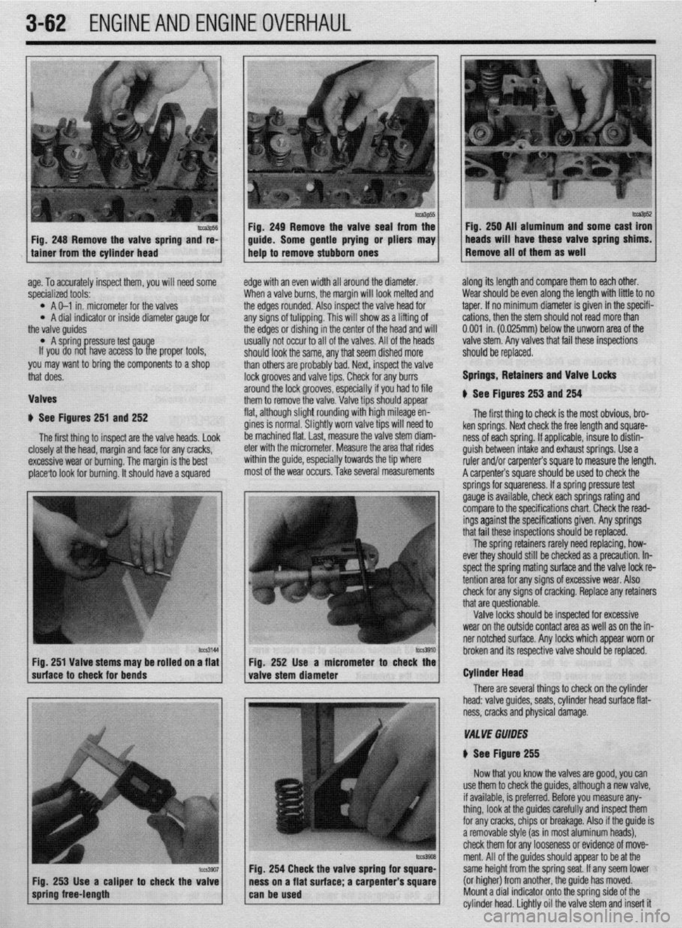
lalves
1 See Figures 251 and 252
The first thing to inspect are the valve heads. Look
E :losely at the head, margin and face for any cracks,
rxcessive wear or burning. The margin is the best
)lace?o look for burning. It should have a squared E
c
edge with an even width all around the diameter.
When a valve burns, the margin will look melted and
the edges rounded. Also inspect the valve head for
any signs of tulipping. This will show as a lifting of
the edges or dishing in the center of the head and will
usually not occur to all of the valves. All of the heads
should look the same, any that seem dished more
than others are probably bad. Next, inspect the valve
lock grooves and valve tips. Check for any burrs
around the lock grooves, especially if you had to file
them to remove the valve. Valve tips should appear
flat, although slight rounding with high mileage en-
gines is normal. Slightly worn valve tips will need to
be machined flat. last, measure the valve stem diam-
eter with the micrometer. Measure the area that rides
within the guide, especially towards the tip where
most of the wear occurs. Take several measurements along its length and compare them to each other.
Wear should be even along the length with little to no
taper. If no minimum diameter is given in the specifi-
cations, then the stem should not read more than
0.001 in. (0.025mm) below the unworn area of the
valve stem. Any valves that fail these inspections
should be replaced.
Springs, Retainers and Valve Locks
$ See Figures 253 and 254
The first thing to check is the most obvious, bro-
ken springs. Next check the free length and square-
ness of each spring. If applicable, insure to distin-
guish between intake and exhaust springs. Use a
ruler and/or carpenter’s square to measure the length.
A carpenter’s square should be used to check the
lCZS3144
I I hrnknn itc Fig. 251 Valve stems may be rolled on a flat Fio. 252 Use a micrometer
suhace to check for bends
valve stem diameter r to check the
I
There are seve Cylinder Head
ral things to check on the cylinder
head: valve guides, seats, cylinder head surface flat-
ness, cracks and physical damage.
VA1 YE GUIDES
N See Figure 255
Now that you know the valves are good, you can
254 Check the valve spring fo
s on a flat surface; a carpenter use them to check the guides, although a new valve,
if available, is preferred. Before you measure any-
thing, look at the guides carefully and inspect them
for any cracks, chips or breakage. Also if the guide is
a removable style (as in most aluminum heads),
check them for any looseness or evidence of move-
ment. All of the guides should appear to be at the
same height from the spring seat. If any seem lower
(or higher) from another, the guide has moved.
Mount a dial indicator onto the sorina side of the
cylinder head. Lightly oil the valve stem and insert it
Page 129 of 408
.
3-68 ENGINEANDENGINEOVERHAUL
crankshaft end-play 8. Install the rear main seal.
the inner portion of the lower land. If the lower
9. After the bearings have been fitted, apply a
lands have high steps, the piston should be re-
light coat of engine oil to the journals and bearings.
placed.
Install the rear main bearing cap. Install all bearing
2. Unless new pistons are installed, be sure to
caps except the thiust bearing cap. Be sure that main
I
install the pistons in the cylinders from which they
bearing caps are installed in original locations.
were removed. The numbers on the connecting rod
Tighten the bearing cap bolts to specifications.
and bearing cap must be on the same side when in-
10. Install the thrust bearing cap with bolts fin-
stalled in the cylinder bore. If a connecting rod is
ger-tight.
ever transposed from one engine or cylinder to an-
11. Pry the crankshaft forward against the thrust
other, new bearings should be fitted and the connect-
surface of upper half of bearing.
ing rod should be numbered to correspond with the *
12. Hold the crankshaft forward and pry the thrust
new cylinder number. The notch on the piston head
bearing cap to the rear. This aligns the thrust sur-
goes toward the front of the engine.
faces of both halves of the bearing.
3. Install all of the rod bearing inserts into the
13. Retain the forward pressure on the crankshaft.
rods and caps.
Tighten the cap bolts to specifications.
4. Install the rings to the pistons. Install the oil
14. Measure the crankshaft end-play as follows:
control ring first, then the second compression ring
a. Mount a dial gauge to the engine block
and finally the top compression ring. Use a piston
and position the tip of the gauge to read from the
ring expander tool to aid in installation and to help
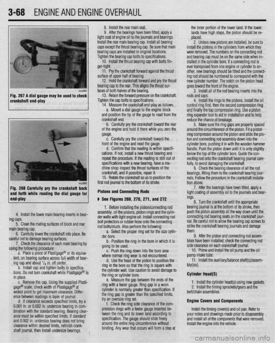
Fig. 266 Carefully pry the crankshafl Ez
and forth while reading the dial gauge for
end-play first rod journal to the bottom of its stroke.
Pistons and Connecting Rods
4. Install the lower main bearing inserts in bear-
ing caps.
5. Clean the mating surfaces of block and rear
main bearing cap.
6. Carefully lower the crankshaft into place. Be
careful not to damage bearing surfaces.
7. Check the clearance of each main bearing by
using the following procedure:
a. Place a piece of Plastigage@ or its equiva-
lent, on bearing surface across full width of bear-
ing cap and about V4 in. off center.
b. Install cap and tighten bolts to specifica-
tions. Do not turn crankshaft while Plastigage@ is
in place.
c. Remove the cap. Using the supplied Plasti-
gage@ scale, check width of Plastigage@ at
widest point to get maximum clearance. Differ-
ence between readings is taper of journal.
d. If clearance exceeds specified limits, try a
0.001 in. or 0.002 in. undersize bearing in com-
bination with the standard bearing. Bearing clear-
ante must be within specified limits. If standard
and 0.002 in. undersize bearing does not bring
clearance within desired limits, refinish crank-
shaft journal, then install undersize bearings. crankshaft end.
b. Carefully pry the crankshaft toward the rear
of the engine and hold it there while you zero the
gauge.
c. Carefully pry the crankshaft toward the
front of the engine and read the gauge.
d. Confirm that the reading is within specifi-
cations. If not, install a new thrust bearing and
repeat the procedure. If the reading is still out of
specifications with a new bearing, have a ma-
chine shop inspect the thrust surfaces of the
crankshaft, and if possible, repair it.
15. Rotate the crankshaft so as to position the
# See Figures 269, 270,271, and 272
1. Before installing the piston/connecting rod
assembly, oil the pistons, piston rings and the cylin-
der walls with light engine oil. Install connecting rod
bolt protectors or rubber hose onto the connecting
rod bolts/studs. Also perform the following:
a. Select the proper ring set for the size cylin-
der bore.
b. Position the ring in the bore in which it is
going to be used.
c. Push the ring down into the bore area
where normal ring wear is not encountered.
d. Use the head of the piston to position the
ring in the bore so that the ring is square with
the cylinder wall. Use caution to avoid damage to
the ring or cylinder bore.
e. Measure the gap between the ends of the
ring with a feeler gauge. Ring gap in a worn
cylinder is normally greater than specification. If
the ring gap is greater than the specified limits,
try an oversize ring set.
f. Check the ring side clearance of the com-
pression rings with a feeler gauge inserted be-
tween the ring and its lower land according to
specification. The gauge should slide freely
around the entire ring circumference without
binding. Any wear that occurs will form a step at reduce the chance of breakage.
5. Make sure the ring gaps are properly spaced
around the circumference of the piston. Fit a piston
ring compressor around the piston and slide the pis-
ton and connecting rod assembly down into the
cylinder bore, pushing it in with the wooden hammer
handle. Push the piston down until it is only slightly
below the top of the cylinder bore. Guide the con-
netting rod onto the crankshaft bearing journal care-
fully, to avoid damaging the crankshaft.
6. Check the bearing clearance of all the rod
bearings, fitting them to the crankshaft bearing jour-
nals. Follow the procedure in the crankshaft installa-
tion above.
7. After the bearings have been fitted, apply a
light coating of assembly oil to the journals and bear-
ings.
8. Turn the crankshaft until the appropriate
bearing journal is at the bottom of its stroke, then
push the piston assembly all the way down until the
connecting rod bearing seats on the crankshaft jour-
nal. Be careful not to allow the bearing cap screws to
strike the crankshaft bearing journals and damage
them.
9. After the piston and connecting rod assem-
blies have been installed, check the connecting rod
side clearance on each crankshaft journal.
10. Prime and install the oil pump and the oil
pump intake tube.
11. Install the auxiliary/balance shaft(s)/assem-
bly(ies).
Cylinder Head(S)
1. Install the cylinder head(s) using new gaskets.
2, Install the timing sprockets/gears and the
belt/chain assemblies.
Engine Covers and Components
Install the timing cover(s) and oil pan. Refer to
your notes and drawings made prior to disassembly
and install all of the components that were removed.
Install the engine into the vehicle.
Page 131 of 408
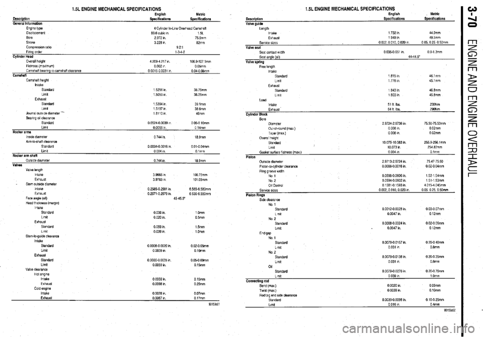
1.5L ENGINE MECHANICAL SPECIFICATIONS English
Metric
Description
Specificationr
Specifications
General Information
Engine type
4 Cylinder In-Line Ovethead Camshaft
Displacement 69 6 cubic I” 15L
sore 2 972 I” 75 5mm
Stroke 3 226 I” 82mm
Compression rat10 921
Firing order
l-3-4-2
Cylinder Head
Overall height 4 209.4 217 I” 1059-107 lmm
Flatness (maximum) 0 002 I” 0 05mm
Camshaft bearing-to-camshaft clearance 0 0016-O 0031 I” 0 04-O OBmm
Camshaft
Camshaft height
Intake
Standard 1 5256 I”. 39 75mm
Limit
1.5059 In 38.25mm
Exhaust
Standard 1 5394 I” 391mm
Llmlt 1 5197 In 38 6mm
Journal outside diameter -
161101”
46mm
Bearing 011 clearance
Standard
0 1X324.0 a)39 I” 0 06-O 10mm
Rocker arms Limit
0 0055 I” 0 14mm
lwde diameter
Arm-to-shalt clearance
Standard 0 744 I”. 18 Smm
0 OCQ4-0 0016 I”. 0 Old 04mm
Llmlt 0 004 I” Olmm
Rocker arm shaft
OutsIde diameter 0 744 I” 16 9mm
Valves
Valve length
Intake 3 9665 I” 100 75mm
Exhaust 3 9763 I” 101.05mm
_ Stem outslde diameter
Intake 0 2585.0 2591 I” 6.565-6 5tlOmm
Exhaust 0 2571-o 2579 I” 6 530-6 55Omm
Face angle (ail)
45-45 5”
Head thickness (margm)
Intake
Standard 0 039 I”. 1 Omm
Llmlt
0 02u In. 05mm
Exhaust
0 059 I”
0 039 I”. 1.5mm
1 .Omm
0 02-O 05mm
0 1Omm
0 05-O OSmm
0 15mm
0 15mm
0 25mm
0 07mm Cescriptlon
Valve guide 1.5L ENGINE MECHANICAL SPECIFICATIONS English
Specifications Metric
Specifications
Length
Intake 1 732 I” 44 Omm
Exhaust
Selwe wes
Valve seat
Seat contact width
Seat angle (all)
Valve spring
Free length
Intake
Standard
Llmlt
Exhaust
Standard
Llmlt 1 949 I” 49 5mm
0002,0010.002cIn 0 05,O 25,O 50mm
0 035-o 051 I” 0 S-1 3mm
44.44 5”
1 615 I” 461mm
1 776 I” 451mm
1 643 I” 46 8mm
1 603 I” 45 6mm
Load
Intake
Exhaust 64 It Ibs. 290Nm
Cylinder Block
Bore
Dnmeter
Out-of-round (ma)
Taper (max.) 2 9724-Z 9736 I” 75 50.75 53mm
0 006 I” 0 02mm
0 006 I” 0 02mm
Overall height
Standard
Llrnbt 10075-10083In 255 9.256 1 mm
10 073 I” 254 62mm
No 1
Standard 0 0012-o 0028 I”. 0 03-O 07mm
Llmlt 0 0047 I” 0 12mm
No 2
Standard 0 OCOE-0 0024 I” 0 02-O 06mm
Llmlt 0 0047 I” 0 l2mm
End gap
No 1
Standard
Limit
No 2
Standard
Ltmlt
01
Standard 0 0079-o 0157 I”.
0 I” 031
0 0079.0.0136 I”
0.031 I”
0 0079.0 0276 I” 0 20-O 40mm
0 8mm
0 20-O 35mm
0.8mm
0 20-O 70mm
Limit
Connecting rod
Bend (mex)
Twst (max) 0 039 I” 1 Omm
0 CO20 I” 0 05mm
0 0039 In 0 10mm
Page 139 of 408
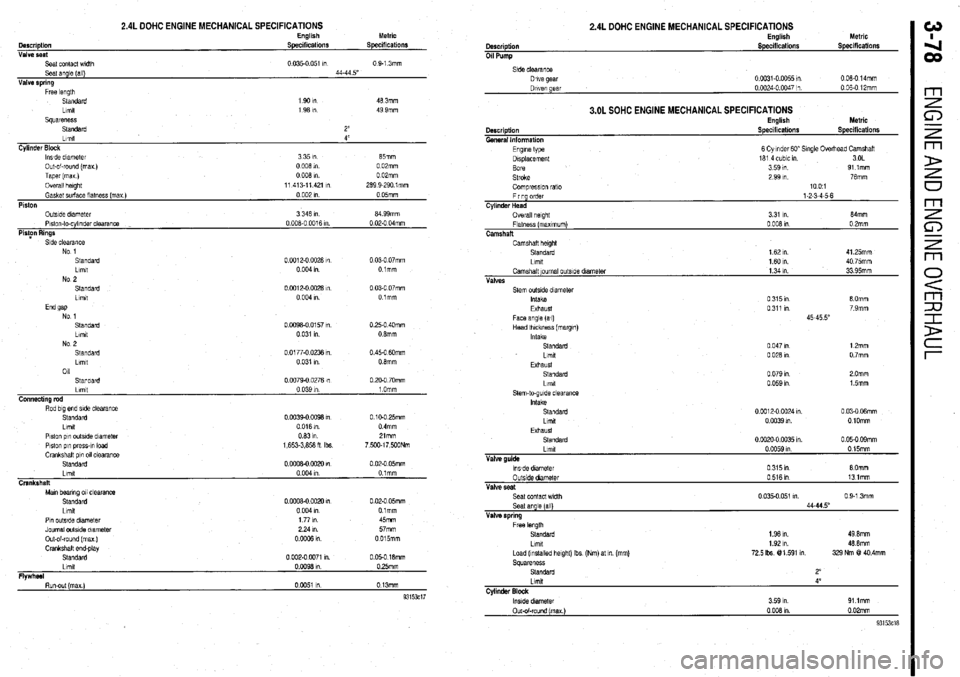
2.4L DOHC ENGINE MECHANICAL SPECIFICATIONS English Metric
Description Specifications Specdications
Valve seat
Seat contact wldlh 0.035-o 051 I”
0 9-l 3mm
Seat angle (all) 44-44 5”
Valve spring
Free length
Standard 1901n 46 3mm
Llmlt
1 96 I” 49 9mm
squareness
Standard 2”
Llmlt 4”
Cylinder Block
lwde diameter 3351n 65mm
Out-of-round (max)
0 006 in 0 02mm
Taper (mu)
0 006 I” 0 02mm
Overall height
11 413-11421 I” 269 9-290 lmm
Gasket surface llatnass (max )
0 002 In 0 05mm
Piston
OutsIde diameter
3 346 In 64 99mm
Plslon-lo-cylinder clearance
0 006.0 0016 m 0 02.0 04mm
PioFn Rings
Side clearance
No 1
Standard
0 0012-O 0026 I”
0 03-O 07mm
Limit
0 004 I”. Olmm
No 2
Standard
0 Cot 2-o 0028 I”
0 03-O 07mm
Llmlt
0 004 I” Olmm
End 9ap
No 1
Standard O.W96-0 0157 I”
0.25-O 40mm
Llmtt
0 031 I”. 0 6mm
NO 9
.__
Standard
Lrmt
011 0 0177-O 0236 I”
0 031 I” 0.45-O 6Omm
0 6mm
Standard
Llmll
Connecting rod
Rod big end side clearance
Standard
Llmlt
Plston pin outsIde dlametar
Piston p,” press-,” load
Crankshatl pin 011 clearance
Standard
Llmlt
Crankshaft
Man bearing 011 clearance
Standard
Llmlt 0
0979.0 0276 I”
0 039 I”
0 0039-o co96 I”
0 016 m.
0631n
1,653.3,656 H Ibs
0
0006-0 0020 I”
0004m
0
0006-0 0020 1”
0 004 I” 0 PO-O 70mm
1 Omm
0 10-O 25mm
0 4mm
Zlmm
7,5Wl7,500Nm
0 02-O 05mm
0 tmm
0 02-O 05mm
Olmm
Pin outstde dlameler
Journal outside diameter
Out-of-round (max )
Crankshalt and-play
Standard
Llmll
Flwhd 177m 45mm
224111 57mm
ooGQ6m 0015mm
0 002-o 0071 I”. 0 05-O 16mm
OW96Ul 0 25mm
I -. Run-out (max)
0 0051 I” 0 13mm
93153ci7
2.4L DOHC ENGINE MECHANICAL SPECIFICATIONS
0 06-O 14mm
3.OL SOHC ENGINE MECHANICAL SPECIFICATIONS
Description
General Information
Engme type
Displacement
Bore
Stroke English
Specifications Metric
Specifications
6 Cylmder GO” Single Overhead Camshatl
161 4 cubic I” 3OL
3 59 I”. 91 lmm
2 99 In. 76mm
Compreswn rat0
Firing order
Cylinder Head
Overall helghl
Flatness (maxImum)
Camshaft 1001
1-2-3-4-5-6
3 31 I” 64mrn
0 006 I” 0 2mm
Camshaft helgM
Standard
1 62 ,n 41 25mm
Llmlt
1601n 40 75mm
Camshaft ~oumal outslde diameter
1 34 I” 33 95mm
Valves
Seat contact width 0 9-1 3mm
Seat angle [all)
Valve spring
Free length
Standard
1.96 I”. 49 0mm
Llmlt
Load (Installed height) Ibs (Nm) at m (mm)
72.5 Ibs @l 591 I”.
Squareness
Standard 46 6mm
329 Nm @! 40.4mm
Lmxt 4’
Cylinder Block m
Page 141 of 408
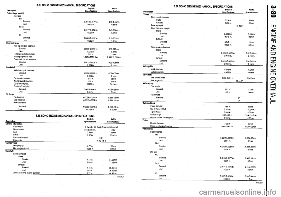
3.OL DOHC ENGINE MECHANICAL SPECIFICATIONS
oescliptiin
Piston Rings (cont’d) English Metric SpeclfiCatiOllS Specifications
End gap No 1
standard
Llmlt
No 2
Standard
Llmlt
011 0 0118-O 0177 ,“.
0.300 40mm
0 031 I” 08mm
0.01770 0236 I” 0 450 6Omm
0 031 I”. 08mm
Standard
Llmlt
Connecting rod
Rod big end side clearance 0.0039-0 0137 I” 0 10-O 35mm
0.039 1” 1 Omm
Slandard
Llmlt
Piston pm outside dnmeter
Piston pi” press-,” load
Crankshaft pm 011 clearance 0.0039-O 0098 m. 0.100 25mm
0016m 0 4mm
087111 22mm
1,652.3,887 fl Ibs.
7,350.17,200Nm
Standard
00012-oOOx)m
0 030 05mm
Llmlt
0 004 I” Olmm
Crankshaft
Mm bearing 011 clearanca
Standard
Llmlt 0 ooO8-0 0020 I” 0 020 05mm
0 004 9”. Dimm
Pm outslde diameter
Journal outs& dlametar
Out-ol-round (max )
Crankshaft end-play
standard
Llmlt
Oil Pump
Tip clearance
Side clearance
Body clearance 2171n
55mm
2521n
Mmm
OoOffiRl 0 015mm
0 002-O 0098 I” 0 05-O 25mm
0 012 I” 03mm
0 CO24.0 0071 m
006018mm
0 0016-O 0039 in. 0 040 1Omm
3.5L SOHC ENGINE MECHANICAL SPECIFICATIONS
Description
General Information
Engme type
Displacement
Bore
Stroke
Comprasslon ratio English Metric
Specifications Specifications
6 Cylinder 60” Single Ovedvzad Camshaft
213 5 cubic I”
3SL
3 65 I”. 93mm
3 37 m. 85 8mm
901
Llmlt
Camshaft ]oumal outs& dtameter 1 44 I”. 36 45mm
1771n
44 95mm
3.5L SOHC ENGINE MECHANICAL SPECIFICATIONS
Llmlt Description
Valve guide Valves
Stem outstde dmmetar
Intake
Exhaust
Face angle (all)
Head thickness (margm)
Intake
Standard
Llmlt
Exhaust
Sl.SldZld
Llmd
stem-to-gude clearance
Intake
standard
Llmlt
EXhaUsl
standarc
0 0059 I” English
0 15mm hletrlc
Speciffcationr
Specificationr
0 236 I”. 6 Omm
0 236 I”. 60mm
4545.5”
0 0039 I” OlOmm
0 019 I”. 05mlll
0 047 I” 12mm
00281n 0 7mm
0
0008-O 0020 I” 0 020 05mm
OW391n 0 lOmm
0
0016-O 0028 I”. 0 040 07mm
lnstde dram&t
OutsIde diameter
Valve seat
Seat contact width
Seal angle (all)
Valve spring
Free knoth 0315m
6 Omm
0 433 I” 11 Omm
0 035-O 051 I” 0 9-l 3mm
44-44 5’
Standard
2 01 I” 51mm
Llmlt
1 97 I”. 5omm
Squareness
Standard
2”
Llmlt
4”
Cylinder Block
lnslde diameter
3 65 I”. 93mm
Out-ol-round (max )
0 008 in 0 02mm
Taper (max ) 0 008 I” 0 02mm
Overall height
8 28-8 29 I” 2104.2106mm
Gasket surface flatness (max)
0 002 I” 0 05mm
Piston
Side clearance
No 1
standard
Llmlt
No. 2
Standard
Llmlt 0 0012-O CO28 1”.
0 03-O 07mm
0 004 In O.lmm
0 CCQ8-0 0024 I” 0 02-O 06mm
0 004 I” Otmm
01
Standard
0 0079-O 0236 I” 0 20-O MXnm
Page 151 of 408
.
4-8 DRIVEABILITYAND EMISSIONS CONTROLS
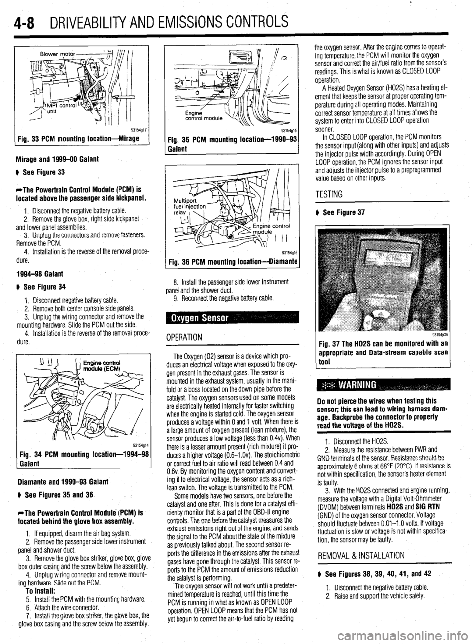
93154g17 Fig. 33 PCM mounting location-Mirage
Mirage and 1999-00 Galant
) See Figure 33
*The Powertrain Control Module (PCM) is
located above the passenger side kickpanel.
1. Disconnect the negative battery cable.
2. Remove the @love box, right side kickpanel
and lower panel assemblies.
3. Unplug the connectors and remove fasteners.
Remove the PCM.
4. Installation is the reverse of the removal proce-
dure.
1994-98 Galant
+ See Figure 34
1, Disconnect negative battery cable.
2. Remove both center console side panels.
3. Unplug the wiring connector and remove the
mounting hardware. Slide the PCM out the side.
4. installation is the reverse of the removal proce-
dure.
Diamante and 1990-93 Galant
) See Figures 35 and 38
*The Powertrain Control Module (PCM) is
located behind the glove box assembly.
1, If equipped, disarm the air bag system
2. Remove the passenger side lower instrument
panel and shower duct.
3. Remove the glove box striker, glove box, glove
box outer casing and the screw below the assembly.
4. Unplug wiring connector and remove mount-
ing hardware. Slide out the PCM.
To install: 5. Install the PCM with the mounting hardware.
6. Attach the wire connector.
7. Install the glove box striker, the glove box, the
glove box casing and the screw below the assembly.
Q3154g15 Fig. 35 PCM mounting location-1990-93
Galant
93154g16 Fig. 38 PCM mounting location-Diamante
8. Install the passenger side lower instrument
panel and the shower duct.
9. Reconnect the negative battery cable
OPERATION
The Oxygen (02) sensor is a device which pro-
duces an electrical voltage when exposed to the oxy-
gen present in the exhaust gases. The sensor is
mounted in the exhaust system, usually in the mani-
fold or a boss located on the down pipe before the
catalyst. The oxygen sensors used on some models
are electrically heated internally for faster switching
when the engine is started cold. The oxygen sensor
produces a voltage within 0 and 1 volt. When there is
a large amount of oxygen present (lean mixture), the
sensor produces a low voltage (less than 0.4~). When
there is a lesser amount present (rich mixture) it pro-
duces a higher voltage (0.6-I .Ov). The stoichiometric
or correct fuel to air ratio will read between 0.4 and
0.6~. By monitoring the oxygen content and convert-
ing it to electrical voltage, the sensor acts as a rich-
lean switch. The voltage is transmitted to the PCM.
Some models have two sensors, one before the
catalyst and one after. This is done for a catalyst eff i-
ciency monitor that is a part of the OBD-II engine
controls. The one before the catalyst measures the
exhaust emissions right out of the engine, and sends
the signal to the PCM about the state of the mixture
as previously talked about. The second sensor re-
ports the difference in the emissions after the exhaust
gases have gone through the catalyst. This sensor re-
ports to the PCM the amount of emissions reduction
the catalyst is performing.
The oxygen sensor will not work until a predeter-
mined temperature is reached, until this time the
PCM is running in what as known as OPEN LOOP
operation. OPEN LOOP means that the PCM has not
yet begun to correct the air-to-fuel ratio by reading the oxygen sensor. After the engine comes to operat-
ing temperature, the PCM will monitor the oxygen
sensor and correct the air/fuel ratio from the sensor’s
readings. This is what is known as CLOSED LOOP
operation.
A Heated Oxygen Sensor (H02S) has a heating el-
ement that keeps the sensor at proper operatmg tem-
perature during all operating modes. Maintaining
correct sensor temperature at all times allows the
system to enter into CLOSED LOOP operation
sooner.
In CLOSED LOOP operation, the PCM monitors
the sensor input (along with other inputs) and adjusts
the injector pulse width accordingly. During OPEN
LOOP operation, the PCM ignores the sensor input
and adjusts the injector pulse to a preprogrammed
value based on other inputs.
TESTING
# See Figure 37
93154p36 Fig. 37 The HD2S can be monitored with an
appropriate and Data-stream capable scan
tool
Do not pierce the wires when testing this
sensor; this can lead to wiring harness dam-
age. Backprobe the connector to properly
read the voltage of the HD2S.
1. Disconnect the H02S.
2. Measure the resistance between PWR and
GND terminals of the sensor. Resistance should be
approximately 6 ohms at 68°F (20°C) If resistance is
not within specification, the sensor’s heater element
is faulty.
3. With the H02S connected and engine running,
measure the voltage with a Digital Volt-Ohmmeter
(DVOM) between terminals
HD2S and SIG RTN (GND) of the oxygen sensor connector. Voltage
should fluctuate between 0.01-l .O volts. If voltage
fluctuation is slow or voltage is not within specifica-
tion, the sensor may be faulty.
REMOVAL &INSTALLATION
) See Figures 38, 39, 40, 41, and 42
1. Disconnect the negative battery cable
2. Raise and support the vehicle safely.
Page 154 of 408
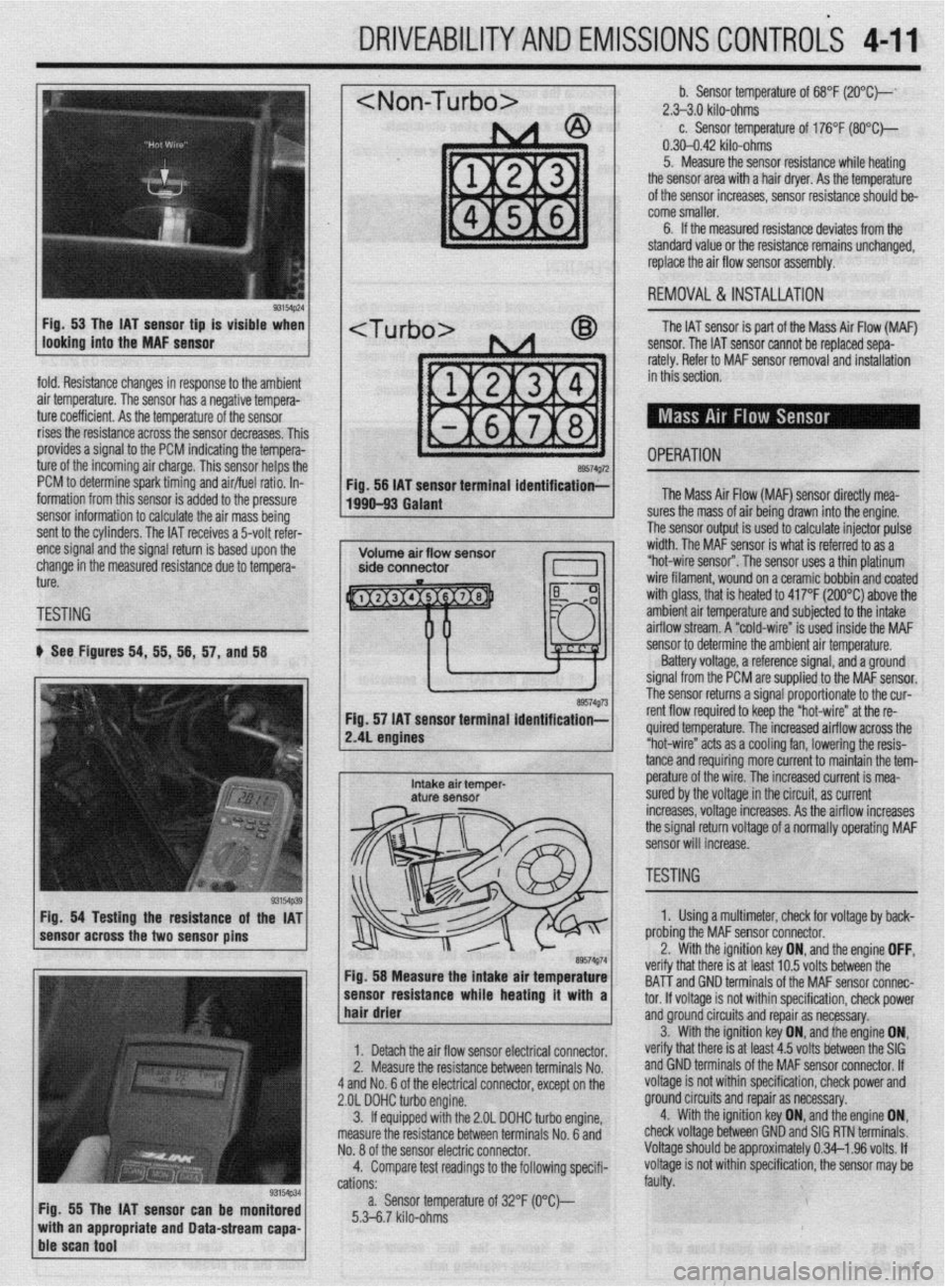
DRIVEABILITYAND EMISSIONS CONTROLi 4-11
fold. Resistance changes in response to the ambient
air temperature. The sensor has a negative tempera-
ture coefficient. As the temperature of the sensor
rises the resistance across the sensor decreases. Thil
provides a signal to the PCM indicating the tempera-
ture of the incoming air charge. This sensor helps the
PCM to determine spark timing and air/fuel ratio. In-
formation from this sensor is added to the pressure
sensor information to calculate the air mass being
sent to the cylinders. The IAT receives a 5-volt refer-
ence signal and the signal return is based upon the
change in the measured resistance due to tempera-
ture.
TESTING
b See Figures 54, 55, 56, 57, and 58
Fig. 54 Testing the resistance of the IAT
sensor across the two sensor pins
Fig. 55 The IAT sensor can be monitored
with an appropriate and Data-stream capa-
ble scan tool
~1 b. Sensor temperature of 68°F (2O”C)--‘ 2.>3.0 kilo-ohms c. Sensor temperature of 176°F (SO*C)-
0.30-0.42 kilo-ohms
5. Measure the sensor resistance while heating
the sensor area with a hair dryer. As the temperature
of the sensor increases, sensor resistance should be-
come smaller.
6. If the measured resistance deviates from the
standard value or the resistance remains unchanged,
replace the air flow sensor assembly.
1 REMOVAL&INSTALLATION
The IAT sensor is part of the Mass Air Flow (MAF)
sensor. The IAT sensor cannot be replaced sepa-
rately. Refer to MAF sensor removal and installation
in this section.
- OPERATION a9574g72 Fig. 56 IAT sensor terminal identification;-
1990-93 Galant The Mass Air Flow (MAF) sensor directly mea-
lres the mass of air being drawn into the engine.
I ?he sensor output is used to calculate injector pulse
width. The MAF sensor is what is referred to as a
“hot-wire sensor”. The sensor uses a thin platinum
wire filament, wound on a ceramic bobbin and coated
with glass, that is heated to 417°F (200°C) above the
amh+en+ nir +PmnPrfijre and subiected to the intake
..I._ ~ ..-.. .“..‘r-,u.. ai mow stream. A “cold-wire” is used inside the MAF
sensor resuirance wnoe nearmg ir wnn a 1
hair drier ‘hat melt: IS al I~“< ,“.., lvllQ UtiLnbtill ,,,=
tnd GND terminals of the MAF sensor connec-
tor. If voltaae is not within specification, check power
1. Detach the air flow sensor electrical connector.
2. Measure the resistance between terminals No.
4 and No. 6 of the electrical connector, except on the
2.OL DOHC turbo engine.
3. ff equipped with the 2.OL DOHC turbo engine,
measure the resistance between terminals No. 6 and
No. 8 of the sensor electric connector.
4. Compare test readings to the following specifi-
cations:
a. Sensor temperature of 32°F (O“C)--
5.3-6.7 kilo-ohms and groundcircuits and repair as necessary.
verify that there is at least 4.5 volts between the SIG 3. With the ignition key ON, and,the engine ON,
and GND terminals of the MAF sensor connector. If
voltage is not within specification, check power and
ground circuits and repair as necessary.
4. With the ignition key ON, and the engine ON,
check voltage between GND and SIG RTN terminals.
Voltage should be approximately 0.34-l .96 volts. If
voltage is not within specification, the sensor may be
faulty.
/ sensor to determine the ambient air temperature.
Battery voltage, a reference signal, and a ground
signal from the PCM are supplied to the MAF sensor.
rho ~pn**r rp+++rns a signal proportionate to the cur-
re. The increased airflow across the
s a cooling fan, lowering the resis-
mo more current to maintain the tem- tance and requir
e^-‘.._^ ^I LL^
I
Intake air temper- pe~a+ure UI me wire. The increased current is mea- aturf sensor sured by the voltage in the circuit, as current
increases, voltage increases. As the airflow increases
the signal return voltage of a normally operating MAF
sensor will increase.
, ~~1 TESTING - II ire” at the re-
89574g74 Fig. 58 Measure the intake air temperature
-----_ ---1-a---- L..- L--1. . . .*a 1. Using a multimeter, check for voltage by back-
nrr\hinn +hn MAF sensor connector.
the ignition key ON, and the engine OFF, .^-^ :- -’ ‘.txt In E; \mltr hahrman tha veriry t
BAT-T i
Page 372 of 408
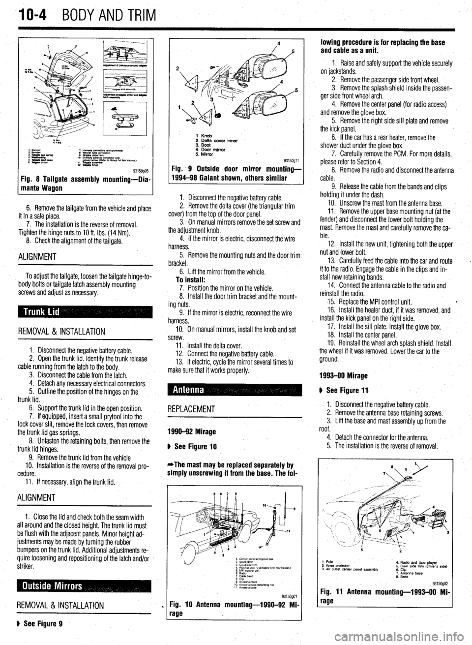
10-4 BODYANDTRIM
Fig. 8 Tailgate assembly mounting-Dia-
mante Wagon
6. Remove the tailgate from the vehicle and place
it in a safe place.
7. The installation is the reverse of removal.
Tighten the hinge
nuts to IO ft. Ibs. (14 Nm).
8. Check the alignment of the tailgate.
ALIGNMENT
To adjust the tailgate, loosen the tailgate hinge-to-
body bolts or tailgate latch assembly mounting
screws and adjust as necessary.
REMOVAL &INSTALLATION
1. Disconnect the negative battery cable.
2. Open the trunk lid. Identify the trunk release
cable running from the latch to the body.
3. Disconnect the cable from the latch.
4. Detach any necessary electrical connectors.
5. Outline the position of the hinges on the
trunk lid.
6. Support the trunk lid in the open position.
7. If equipped, insert a small prytool into the
lock cover slit, remove the lock covers, then remove
the trunk lid gas springs.
8. Unfasten the retaining bolts, then remove the
trunk lid hinges.
9. Remove the trunk lid from the vehicle
10. Installation is the reverse of the removal pro-
cedure.
11. If necessary, align the trunk lid.
ALIGNMENT
1. Close the lid and check both the seam width
all around and the closed height. The trunk lid must
be flush with the adjacent panels. Minor height ad-
justments may be made by turning the rubber
bumpers on the trunk lid. Additional adjustments re-
quire loosening and repositioning of the latch and/or
striker.
REMOVAL &INSTALLATION
? See Figure 9
1. Knob 2. Delta cover inner
3. Boot
4. Door mirror
5. Mirror
Fig. .9 Outside door mirror
1994-98 Galant shown
, others 9315oQ1 i mounting-
similar
1. Disconnect the negative battery cable.
2. Remove the delta cover (the triangular trim
cover) from the top of the door panel.
3. On manual mirrors remove the set screw and
the adjustment knob.
4. If the mirror is electric, disconnect the wire
harness.
5. Remove the mounting nuts and the door trim
bracket.
6. Lift the mirror from the vehicle.
To install: 7. Position the mirror on the vehicle.
8. Install the door trim bracket and the mount-
ing nuts.
9. If the mirror is electric, reconnect the wire
harness.
IO. On manual mirrors, install the knob and set
screw.
11. Install the delta cover.
12. Connect the negative battery cable.
13. If electric, cycle the mirror several times to
make sure that it works properly.
# See Figure 11
REPLACEMENT
1990-92 Mirage
b
See Figure 10
*The mast may be replaced separately by
simply unscrewing it from the base. The fol-
1. center panel and glove box
2 scuff plate
3 cowl 51ae wm
4 Washer duct
7 CaMeband
8 cap
9 Anrsnna mast
10 Antenna base “ourmng ““f
11 Antennz.base
%i%Qol
Fig. 10 Antenna mounting-1990-92 Mi-
rage lowing procedure is for replacing the base
and cable as a unit.
1 I Raise and safely support the vehicle securely
on jackstands.
2. Remove the passenger side front wheel.
3. Remove the splash shield inside the passen-
ger side front wheel arch.
4. Remove the center panel {for radio access)
and remove the glove box.
5. Remove the right side sill plate and remove
the kick panel.
6. If the car has a rear heater, remove the
shower duct under the glove box.
7. Carefully remove the PCM. For more details,
please refer to Section 4.
8. Remove the radio and disconnect the antenna
cable.
9. Release the cable from the bands and clips
holding it under the dash.
10. Unscrew the mast from the antenna base.
II. Remove the upper base mounting nut (at the
fender) and disconnect the lower bolt holding the
mast. Remove the mast and carefully remove the ca-
ble.
12. Install the new unit, tightening both the upper
nut and lower bolt.
13. Carefully feed the cable into the car and route
it to the radio. Engage the cable in the clips and in-
stall new retaining bands.
14. Connect the antenna cable to the radio and
reinstall the radio.
15. Replace the MPI control unit. t
16. Install the heater duct, if it was removed, and
install the kick panel on the right side.
17. Install the sill plate. Install the glove box.
18. Install the center panel.
19. Reinstall the wheel arch splash shield. Install
the wheel if it was removed. Lower the car to the
ground.
1993-00 Mirage
I. Disconnect the negative battery cable.
2. Remove the antenna base retaining screws.
3. Lift the base and mast assembly up from the
roof.
4. Detach the connector for the antenna.
5. The installation is the reverse of removal.
1. Pole
2. Knee protactor
3. Air outlet center panel assembly 4. Radto and laps player
5. Cowl side trim (driver’s side)
6. Chp
7. Antenna base
6. Base
931 !iogo2 Fig. 11 Antenna mounting-1993-00 Mi-
rage