tailgate MITSUBISHI DIAMANTE 1900 Repair Manual
[x] Cancel search | Manufacturer: MITSUBISHI, Model Year: 1900, Model line: DIAMANTE, Model: MITSUBISHI DIAMANTE 1900Pages: 408, PDF Size: 71.03 MB
Page 31 of 408
.
1-32 GENERALINFORMATIONAND MAINTENANCE
CONDITION
EFFECT
CAUSE
CORRECTION UNDER-INFLATION
EXCESSIVE SPEED’ WORN OR OUT-
OF-ALIGNMENT
ADJUST PRESSURE TO
SPECIFICATIONS WHEN
TIRES ARE COOL
ROTATE TIRES
/ BALANCE WHEELS INSPECT SUSPENSION
HAVE TIRE INSPECTED FOR FURTHER USE.
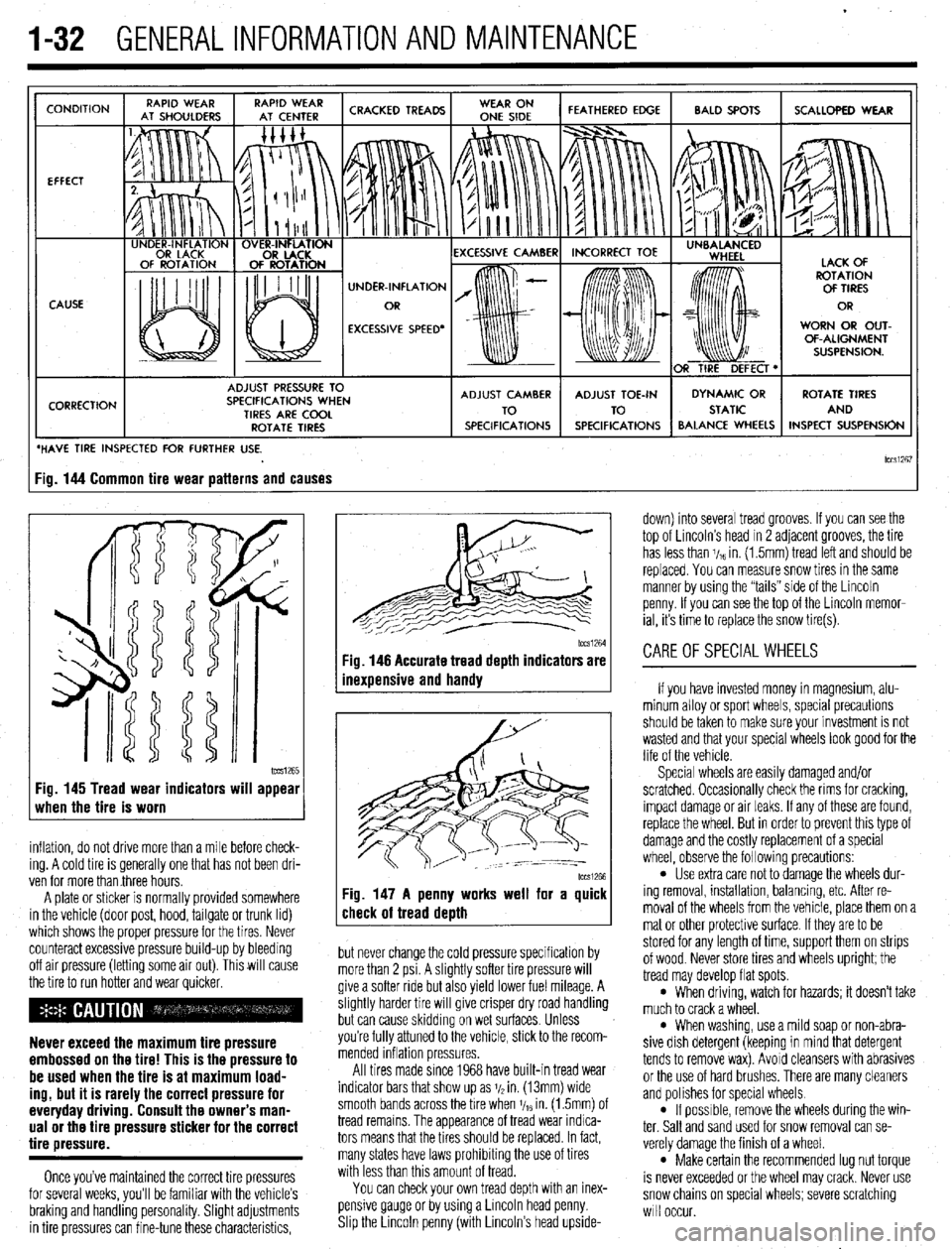
lCCSi267 ig. 144 Common tire wear patterns and causes
1~~~1265 Fig. 145 Tread wear indicators will appear
when the tire is worn
inflation, do not drive more than a mile before check-
ing. A cold tire is generally one that has not been dri-
ven for more than three hours.
A plate or sticker is normally provided somewhere
in the vehicle (door post, hood, tailgate or trunk lid)
which shows the proper pressure for the tires. Never
counteract excessive pressure build-up by bleeding
off air pressure (letting some air out). This will cause
the tire to run hotter and wear quicker.
Never exceed the maximum tire pressure
embossed on the tire! This is the pressure to
be used when the tire is at maximum load-
ing, but it is rarely the correct pressure for
everyday driving. Consult the owner’s man-
ual or the tire pressure sticker for the correct
tire pressure.
Once you’ve maintained the correct tire pressures
for several weeks, you’ll be familiar with the vehicle’s
braking and handling personality. Slight adjustments
in tire pressures can fine-tune these characteristics,
1~~~1264 Fig. 146 Accurate tread depth indicators are
inexuensive and handv
Fig. 147 A penny works well for a quick
check of tread death
but never change the cold pressure specification by
more than 2 psi. A slightly softer tire pressure will
give a softer ride but also yield lower fuel mileage. A
slightly harder tire will give crisper dry road handling
but can cause skidding on wet surfaces. Unless
you’re fully attuned to the vehicle, stick to the recom-
mended inflation pressures.
All tires made since 1968 have built-in tread wear
indicator bars that show up as j/2 in. (13mm) wide
smooth bands across the bre when V,~ in. (1.5mm) of
tread remains. The appearance of tread wear indica-
tors means that the tires should be replaced. In fact,
many states have laws prohibiting the use of tires
with less than this amount of tread.
You can check your own tread depth with an inex-
pensive gauge or by using a Lincoln head penny.
Shp the Lrncoln penny (with Lincoln’s head upside- down) into several tread grooves. If you can see the
top of Lincoln’s head in 2 adjacent grooves, the tire
has less than V,~ in. (1.5mm) tread left and should be
replaced. You can measure snow tires in the same
manner by using the “tails” side of the Lincoln
penny. If you can see the top of the Lincoln memor-
ial, its time to replace the snow tire(s).
CAREOFSPECIALWHEELS
If you have invested money in magnesium, alu-
minum alloy or sport wheels, special precautions
should be taken to make sure your investment is not
wasted and that your special wheels look good for the
life of the vehicle.
Special wheels are easily damaged and/or
scratched. Occasionally check the rims for cracking,
impact damage or air leaks. If any of these are found,
replace the wheel. But in order to prevent this type of
damage and the costly replacement of a special
wheel, observe the following precautions:
l Use extra care not to damage the wheels dur-
ing removal, installation, balancing, etc. After re-
moval of the wheels from the vehicle, place them on a
mat or other protective surface. If they are to be
stored for any length of time, support them on strips
of wood. Never store tires and wheels upright; the
tread may develop flat spots.
l When driving, watch for hazards; it doesn’t take
much to crack a wheel.
l When washing, use a mild soap or non-abra-
sive dish detergent (keeping in mind that detergent
tends to remove wax). Avoid cleansers with abrasives
or the use of hard brushes. There are many cleaners
and polishes for special wheels.
l If possrble, remove the wheels during the win-
ter. Salt and sand used for snow removal can se-
verely damage the finish of a wheel.
l Make certain the recommended lug nut torque
is never exceeded or the wheel may crack. Never use
snow chains on special wheels; severe scratching
will occur.
Page 225 of 408
6-22 CHASSIS ELECTRICAL
b
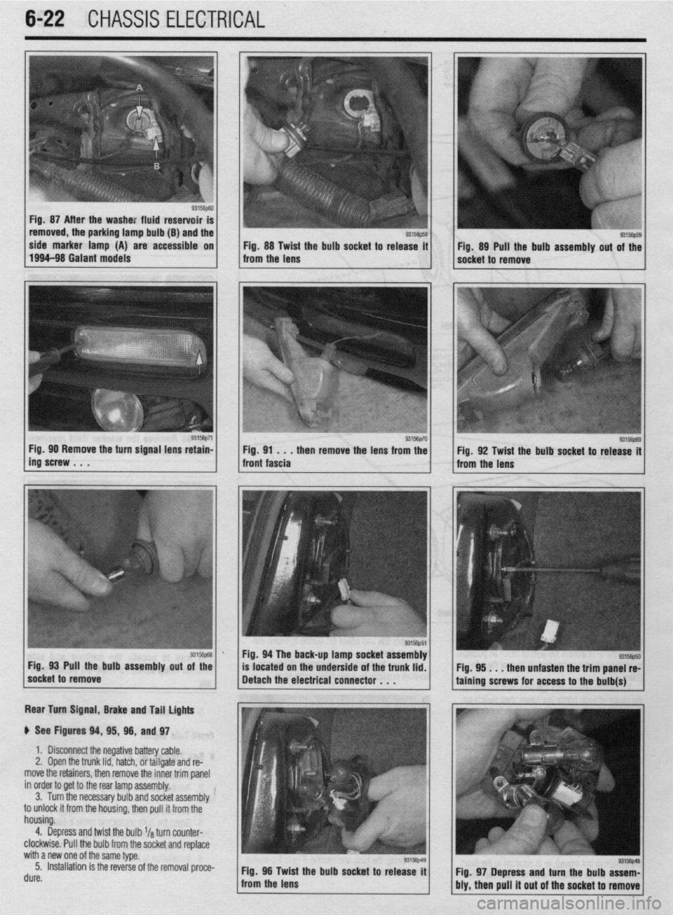
Fig. 87 After the washe: fluid reservoir
removed, the parking lamp bulb (B) and the
side marker lamp (A) are accessible on
Fig. 88 Twist the bulb socket to release it
1994-98 Galant models
from the lens Fig. 89 Pull the bulb assembly out of the
socket to remove
g3156p71 / Fig 90 Remove the turn signal lens retain-
ing’screw . . . . then remove the lens from the
Rear Turn Signal, Brake and Tail lights
p See Figures 94, 95, 96, and 97.
1. Disconnect the negative battery cable.
2, Open the trunk lid, hatch, or tailgate and re-
move the retainers, then remove the inner trim panel
in order to get to the rear lamp assembly.
3. Turn the necessary bulb and socket assembly
to unlock it from the housing, then pull it from the
housing.
4. Depress and twist the bulb l/a turn counter-
clockwise. Pull the bulb from the socket and replace
with a new one of the same type.
5. Installation is the reverse of the removal proce-
rl. ._^
UUIt?. Fig. 96 Twid
: the bulb socket to release it
from the lens
93156p69 Fig. 92 Twist the bulb socket to release it
from the lens
I
Fig. 94 The back-up lamp socket assembly
Pull the bulb assembly
out of the
located on the underside of the trunk lid.
. . . then unfasten the trim panel re-
Fig. 97 Depress and turn the bulb assem-
bly, then pull it out of the socket to remove
Page 369 of 408
EXTERIOR IO-2
DOORS IO-2
REMOVAL&INSTALLATION IO-2
HOOD IO-2
REMOVAL&INSTALLATION IO-2
ALIGNMENT IO-3
HATCH IO-3
REMOVAL & INSTALLATION IO-3
ALIGNMENT IO-3
TAILGATE IO-3
REMOVAL & INSTALLATION IO-3
ALIGNMENT IO-3
TRUNK LID IO-3
REMOVAL &INSTALLATION IO-3
ALIGNMENT IO-3
OUTSIDE MIRRORS IO-3
REMOVAL &INSTALLATION IO-3
ANTENNA IO-4
REPLACEMENT IO-4
FENDERS IO-4
REMOVAL & INSTALLATION IO-4
INTERIOR 1
O-6 INSTRUMENTPANEL IO-6
REMOVAL & INSTALLATION IO-6
FLOOR CONSOLE IO-6
REMOVAL & INSTALLATION IO-6
DOOR PANELS IO-7
REMOVAL & INSTALLATION IO-7
DOORHANDLE/LATCHASSEMBLY IO-IO
REMOVAL &INSTALLATION IO-IO
DOOR LOCKCYLINDER IO-IO
REMOVAL &INSTALLATION IO-IO
HATCH/TAILGATE/TRUNKLID LOCK
CYLINDER IO-IO
REMOVAL &INSTALLATION IO-IO
TAILGATE/HATCH HANDLE IO-IO
REMOVAL &INSTALLATION IO-IO
DOORGLASSANDREGULATOR IO-IO
REMOVAL&INSTALLATION IO-IO
ELECTRIC WINDOW MOTOR IO-IO
REMOVAL &INSTALLATION IO-IO
INSIDE REAR VIEW MIRROR IO-IO
REPLACEMENT IO-IO
SEATS IO-IO
REMOVAL & INSTALLATION IO-IO
POWERSEATMOTOR IO-11
REMOVAL &INSTALLATION IO-11
SPECIFICATIONS CHART
TORQUE SPECIFICATIONS IO-14
4
Page 371 of 408
BODYANDTRIM 10-3
3. Check the hood latch operation; it should en-
gage easily and smoothly. The latch should release
without the use of excessive force. The hood latch
mounting bolts may be loosened; the latch can be
adjusted left/right or up/down to compensate for the
hood striker position.
4. With the hood closed and latched, check the
height of the hood. It should sit even with the fender
tops; this dimension may be adjusted by turning the
hood stops to a higher or lower position. Note that
adjusting these stops may require readjustment of the
latch to position the hood correctly.
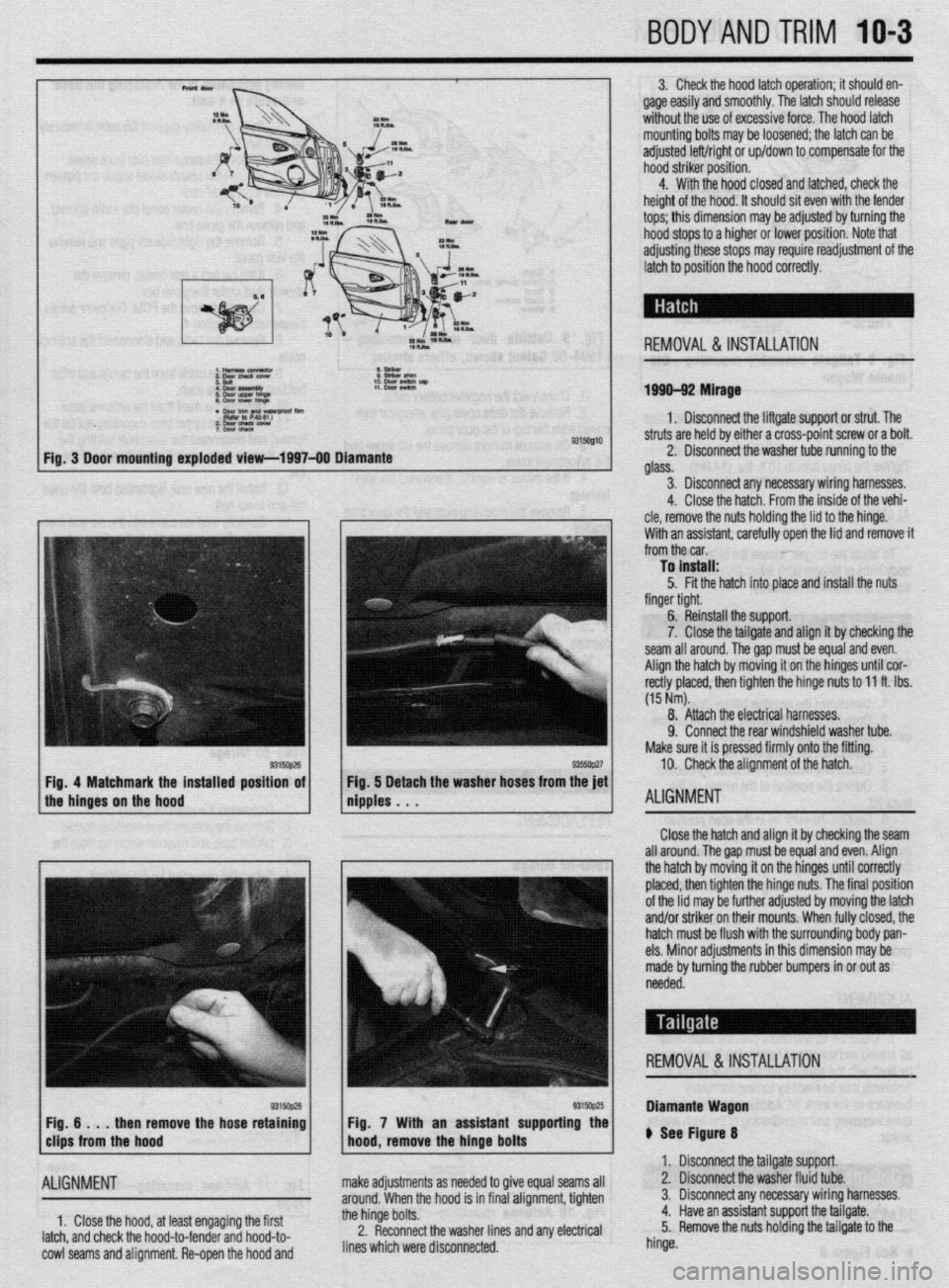
REMOVAL &INSTALLATION
1999-92 Mirage
1. Disconnect the liftgate support or strut. The
9315Ql10 struts are held by either a cross-point screw or a bolt.
2. Disconnect the washer tube running to the
glass.
3. Disconnect any necessary wiring harnesses.
4. Close the hatch. From the inside of the vehi-
cle, remove the nuts holding the lid to the hinge.
With an assistant. carefullv ooen the lid and remove it
from the car. ’
To install:
5. Fit the hatch into place and install the nuts
finger tight.
6. Reinstall the support.
7. Close the tailgate and align it by checking the
seam all around. Thegap must be equal and even.
Align the hatch by moving it on the hinges until cor-
rectly placed, then tighten the hinge nuts to 11 ft. Ibs.
(15 Nm).
8. Attach the electrical harnesses.
9. Connect the rear windshield washer tube.
Make sure it is pressed firmly onto the fitting.
10. Check the alignment of the hatch.
ALIGNMENT
Close the hatch and align it by checking the seam
all around. The gap must be equal and even. Align
the hatch by moving it on the hinges until correctly
placed, then tighten the hinge nuts. The final position
of the lid may be further adjusted by moving the latch
and/or striker on their mounts. When fully closed, the
hatch must be flush with the surrounding body pan-
els. Minor adjustments in this dimension may be
made by turning the rubber bumpers in or out as
needed.
REMOVAL &INSTALLATION
then remove the hose retaining
ALIGNMENT
1, Close the hood, at least engaging the first
latch, and check the hood-to-fender and hood-to-
cowl seams and alignment. Re-open the hood and Fig. 7 With an assistant supporting the
make adjustments as needed to give equal seams all
around. When the hood is in final alignment, tighten
the hinge bolts.
2. Reconnect the washer lines and any electrical
lines which were disconnected. Diamante Wagon
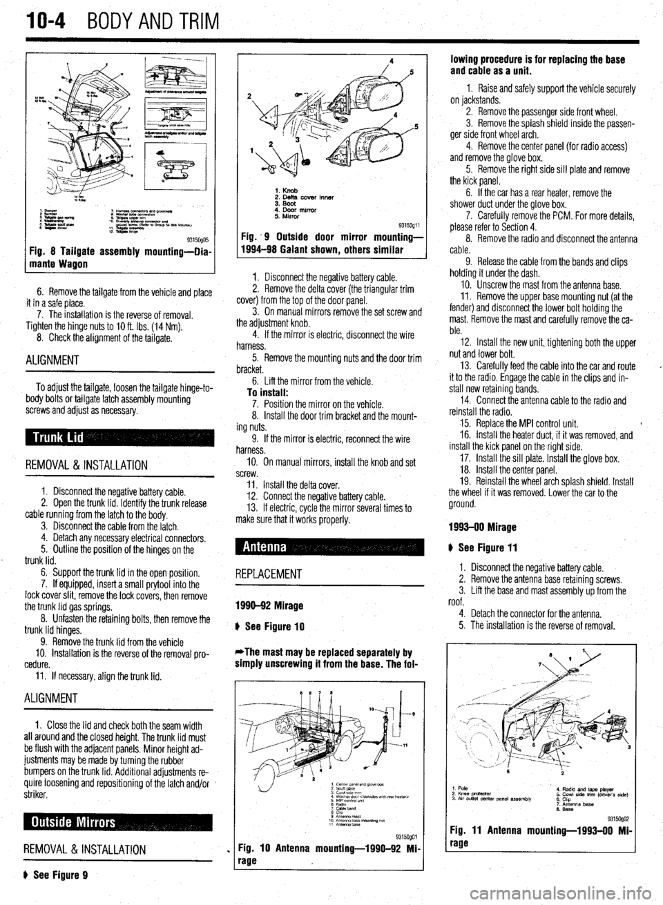
ti See Figure 8
1. Disconnect the tailgate support.
2. Disconnect the washer fluid tube.
3. Disconnect any necessary wiring harnesses.
4. Have an assistant support the tailgate.
5. Remove the nuts holding the tailgate to the
hinge.
Page 372 of 408
10-4 BODYANDTRIM
Fig. 8 Tailgate assembly mounting-Dia-
mante Wagon
6. Remove the tailgate from the vehicle and place
it in a safe place.
7. The installation is the reverse of removal.
Tighten the hinge
nuts to IO ft. Ibs. (14 Nm).
8. Check the alignment of the tailgate.
ALIGNMENT
To adjust the tailgate, loosen the tailgate hinge-to-
body bolts or tailgate latch assembly mounting
screws and adjust as necessary.
REMOVAL &INSTALLATION
1. Disconnect the negative battery cable.
2. Open the trunk lid. Identify the trunk release
cable running from the latch to the body.
3. Disconnect the cable from the latch.
4. Detach any necessary electrical connectors.
5. Outline the position of the hinges on the
trunk lid.
6. Support the trunk lid in the open position.
7. If equipped, insert a small prytool into the
lock cover slit, remove the lock covers, then remove
the trunk lid gas springs.
8. Unfasten the retaining bolts, then remove the
trunk lid hinges.
9. Remove the trunk lid from the vehicle
10. Installation is the reverse of the removal pro-
cedure.
11. If necessary, align the trunk lid.
ALIGNMENT
1. Close the lid and check both the seam width
all around and the closed height. The trunk lid must
be flush with the adjacent panels. Minor height ad-
justments may be made by turning the rubber
bumpers on the trunk lid. Additional adjustments re-
quire loosening and repositioning of the latch and/or
striker.
REMOVAL &INSTALLATION
? See Figure 9
1. Knob 2. Delta cover inner
3. Boot
4. Door mirror
5. Mirror
Fig. .9 Outside door mirror
1994-98 Galant shown
, others 9315oQ1 i mounting-
similar
1. Disconnect the negative battery cable.
2. Remove the delta cover (the triangular trim
cover) from the top of the door panel.
3. On manual mirrors remove the set screw and
the adjustment knob.
4. If the mirror is electric, disconnect the wire
harness.
5. Remove the mounting nuts and the door trim
bracket.
6. Lift the mirror from the vehicle.
To install: 7. Position the mirror on the vehicle.
8. Install the door trim bracket and the mount-
ing nuts.
9. If the mirror is electric, reconnect the wire
harness.
IO. On manual mirrors, install the knob and set
screw.
11. Install the delta cover.
12. Connect the negative battery cable.
13. If electric, cycle the mirror several times to
make sure that it works properly.
# See Figure 11
REPLACEMENT
1990-92 Mirage
b
See Figure 10
*The mast may be replaced separately by
simply unscrewing it from the base. The fol-
1. center panel and glove box
2 scuff plate
3 cowl 51ae wm
4 Washer duct
7 CaMeband
8 cap
9 Anrsnna mast
10 Antenna base “ourmng ““f
11 Antennz.base
%i%Qol
Fig. 10 Antenna mounting-1990-92 Mi-
rage lowing procedure is for replacing the base
and cable as a unit.
1 I Raise and safely support the vehicle securely
on jackstands.
2. Remove the passenger side front wheel.
3. Remove the splash shield inside the passen-
ger side front wheel arch.
4. Remove the center panel {for radio access)
and remove the glove box.
5. Remove the right side sill plate and remove
the kick panel.
6. If the car has a rear heater, remove the
shower duct under the glove box.
7. Carefully remove the PCM. For more details,
please refer to Section 4.
8. Remove the radio and disconnect the antenna
cable.
9. Release the cable from the bands and clips
holding it under the dash.
10. Unscrew the mast from the antenna base.
II. Remove the upper base mounting nut (at the
fender) and disconnect the lower bolt holding the
mast. Remove the mast and carefully remove the ca-
ble.
12. Install the new unit, tightening both the upper
nut and lower bolt.
13. Carefully feed the cable into the car and route
it to the radio. Engage the cable in the clips and in-
stall new retaining bands.
14. Connect the antenna cable to the radio and
reinstall the radio.
15. Replace the MPI control unit. t
16. Install the heater duct, if it was removed, and
install the kick panel on the right side.
17. Install the sill plate. Install the glove box.
18. Install the center panel.
19. Reinstall the wheel arch splash shield. Install
the wheel if it was removed. Lower the car to the
ground.
1993-00 Mirage
I. Disconnect the negative battery cable.
2. Remove the antenna base retaining screws.
3. Lift the base and mast assembly up from the
roof.
4. Detach the connector for the antenna.
5. The installation is the reverse of removal.
1. Pole
2. Knee protactor
3. Air outlet center panel assembly 4. Radto and laps player
5. Cowl side trim (driver’s side)
6. Chp
7. Antenna base
6. Base
931 !iogo2 Fig. 11 Antenna mounting-1993-00 Mi-
rage
Page 379 of 408
BODYANDTRiVl 1041
8. llnm all mtainar din!: xc! .wnnratmi rmnnve -.*I-_.. .I._. ..I. -..r-~.--“* -.-.- I( .” .I._._ the dot jr panel assembly.
9. Carefully remove any retainer clips that re-
mained in the door during panel removal. If dam-
aaed. reolace the retainer clios.
- 10. if necessary, remove’the waterproof film from
the door.
To install:
11. If removed, install the waterproof film from
. .
tne aoor.
12. Install and missing or damaged retainer clips
into the door panel.
- .- ” - 13. . - Install the door panel onto the vehicle. Push . - -. ” - ret;liners intn the hnlss in the rlnnr until thev lnck intn . - - - -. -. . . . “, - ” . .- position. If any clips do not lock, replace with new 4. Remove the lock cylinder from the trunk lid,
hatch, or tailgate. T- 1-a-11.
REMOVAL &INSTALLATION
1. Disconnect the r
negative battery cable.
2. If necessary, ren love any trim in on the under-
side of the trunk lid, hz
Itch, or tailgate.
3. Release locking tab retaining the lock cylinder
to outside handle.
9315opo5 1 Fig. 46 Remove the two front door panel re-
taining screws . , . IU Inrlall; 5. Place the lock cylinder into the opening on the
ones.
14. The remainder of installation is the reverse of
removal. trunk lid, hatch, or tailsate. -
6. Snap the locking tab into place retaining the
lock cylinder to the outside handle.
7. If removed, install any trim in on the underside
of the trunk lid, hatch, or tailgate.
8. Connect the negative battery able:
REMOVAL &INSTALLATION
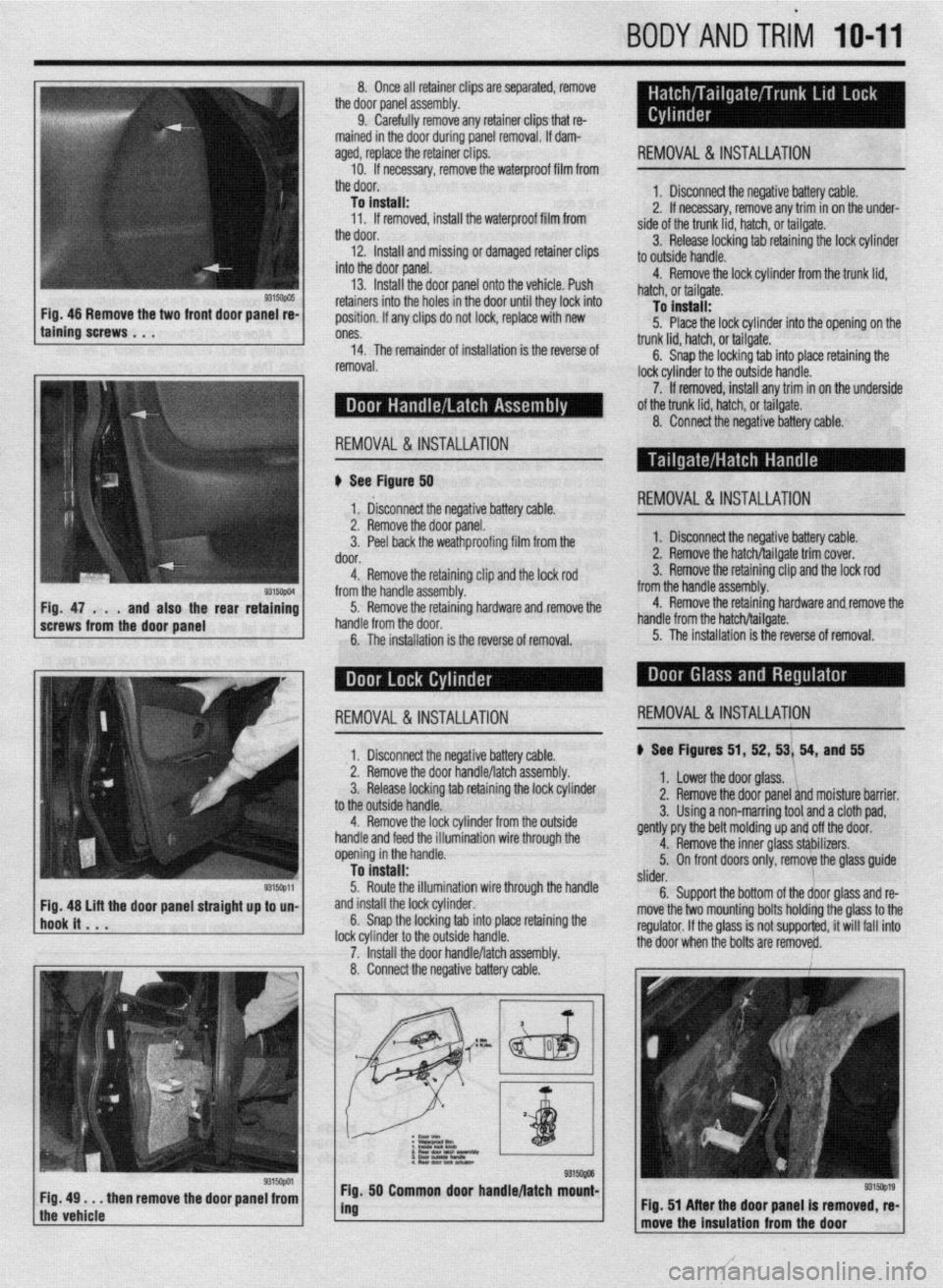
II See Figurd 50
1‘ &connect the negative battery cable. REMOVAL&INSTALLATION
9315ctpm Fig. 47 . . .
and also the rear retaining
screws from the door panel 2. Remove the door panel.
3. Peel back the weathproofing film from the
door.
4. Remove the retaining clip and the lock rod
from the handle assembly.
5. Remove the retaining hardware and remove the
handle from the door.
6. The installation is the reverse of removal. 1. Disconnect the negative battery cable.
2. Remove the hatch/tailgate trim cover.
3. Remove the retaining clip and the lock rod
from the handle assembly.
4. Remove the retaining hardware and.remove the
handle from the hatch/tailgate.
5. The installation is the reverse of removal.
I 1. Disconnect the neaative batterv cable. ) See Figures 51, 52, 53/ 54, and 55 REMOVAL&INSTALLATION REMOVAL&INSTALLATION
2. Remove the door ~andle/latchassembly.
3. Release locking tab retaining the lock cylinder
to the outside handle.
4. Remove the lock cylinder from the outside
handle and feed the illumination wire through the
opening in the handle.
To install:
5. Route the illumination wire through the handle
and install the lock cylinder.
6. Snap the locking tab into place retaining the
lock cvlinder to the outside handle.
7. ‘Install the door handle/latch assembly.
8. Connect the negative battery cable. 1. Lower the door glass. ‘1,
2. Remove the door panel and moisture barrier.
3. Using a non-marring tool and a cloth pad,
gently pry the belt molding up and off the door.
4. Remove the inner glass sthbilizers.
5. On front doors only, remove the glass guide
/
slider.
6. Support the bottom of the door glass and re-
move the two mounting bolts holdirtg the glass to the
regulator. If the glass is not supporfed, it will fail into
+I%? Ann. . ..hmn hr. l..4+s are remove&.
9315opa Fig, 49 . . . then remove the door panel from
the vehicle 50 Common door handle/latch mount-
I
, Flg. 51 After the door panel is removed, re-
move the Insulation from the door
Page 382 of 408
.
IO-14 BODYANDTRIM
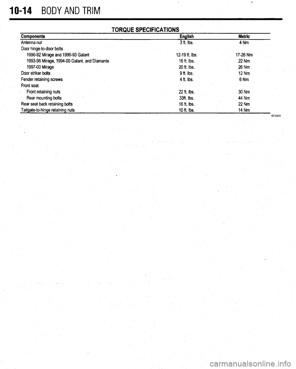
TORQUE SPECIFICATIONS Components English Metric
Antenna nut 3 ft. Ibs. 4Nm
Door hinge-to-door bolts
1990-92 Mirage and 1990-93 Galant 12-19 ft. Ibs. 17-26 Nm
1993-96 Mirage, 1994-00 Galant, and Diamante 16 ft. Ibs. 22,Nm
1997-00 Mirage 20 ft. Ibs. 26 Nm
Door striker bolts 9ft. Ibs. 12Nm
Fender retaining screws 4 ft. Ibs. 6Nm
Front seat
Front retaining nuts 22 ft. Ibs. 30 Nm
Rear mounting bolts 33ft. Ibs. 44 Nm
Rear seat back retaining bolts 16 ft. Ibs. 22 Nm
Tailgate-to-hinge retaining nuts
10 ft. Ibs. 14 Nm
9315ocol
,
Page 405 of 408
MASTER INDEX 11-23
GENERALINFORMAITON 3-65
INSPECTION 3-65
REFINISHING 3-67
ENGINE FAN 3-19
REMOVAL & INSTALLATION 3-19
ENGINE MECHANICAL 3-1
ENGINE OVERHAUL TIPS 3-58
CLEANING 3-58
OVERHAUL TIPS 3-58
REPAIRING DAMAGEDTHREADS 3-59
TOOLS 3-58
ENGINE PREPARATION 3-59
ASSEMBLY 3-64
DISASSEMBLY 3-60
INSPECTION 3-
REFINISHING & REPAIRING 3-63
ENGINE RECONDITIONING 3-57
ENGINE START-UP AND BREAK-IN
3-69
BREAKING IT IN 3-69
KEEP IT MAINTAINED 3-69
STARTING THE ENGINE 3-69
ENGINE 'l-33
OIL& FILTER CHANGE 1-34
OILLEVELCHECK 1-33
ENGINE 3-1
REMOVAL&INSTALLATION 3-l
ENGlNECONTROLUNIT/POWERTRAINCONTROLMODULE(ECU/PCM)
4-7
OPERATION 4-7
REMOVAL&INSTALLATION 4-7
ENGINECOOLANTTEMPERATURESENSOR
4-10
OPERATION 4-10
REMOVAL&INSTALLATION 4-10
TESTING 4-10
ENGINECOOLANTTEMPERATURESENDING
UNIT 2-11
REMOVAL&INSTALLATION 2-11
TESTING 2-11
ENGINE IDENTIFICATION NUMBER l-10
ENTERTAINMENT SYSTEMS 6-14
EVAPORATIVECANISTER I-16
SERVICING 1-16
' EVAPORATIVEEMISSIONCONTROLS 4-2
COMPONENTTESTING 4-3
OPERATION 4-2
REMOVAL&INSTALLATION 4-4
EXHAUST MANIFOLD 3-14
REMOVAL & INSTALLATION 3-14
EXHAUST SYSTEM 3-55
EXHAUSTGASRECIRCULATION SYSTEM
4-5
COMPONENTTESTING 4-5
OPERATION 4-5
REMOVAL&INSTALLATION 4-6
EXTERIOR 1 O-2
FASTENERS, MEASUREMENTS AND CONVERSIONS 1-6
. FENDERS 10-4
REMOVAL &INSTALLATION IO-4
FIRING ORDERS 2-7
FLASHERS 6-28
REPLACEMENT 6-28
FLOOR CONSOLE IO-6
REMOVAL& INSTALLATION IO-6 1
FLUID PAN 7-10
FLUID DISPOSAL 1-33
FLUIDS AND LUBRICANTS 1-33
FLYWHEEVDRIVEPLATE 3-55
REMOVAL & INSTALLATION 3-55
FRONT CRANKSHAFT SEAL 3-48
REMOVAL & INSTALLATION 3-48
FRONT SUSPENSION 8-4 FRONTWHEELDRIVEMODELS 1-44
FUELANDENGINEOILRECOMMENDATIONS 1-33
ENGINEOIL l-33
FUEL 1-33
OPERATION IN FOREIGN COUNTRIES
1-33
FUEL LINE FITTINGS 5-2
REMOVAL&INSTALLATION 5-2
FUEL RAIL AND INJECTORS(S)
5-4
REMOVAL &INSTALLATION 5-4
TESTING 5-8
FUELSYSTEM SERVICE PRECAUTIONS 5-3
FUELFILTER 1-15
REMOVAL&INSTALLATION l-15
FUEL LINES AND FITTINGS 5-2
FUELPRESSUREREGULATOR 5-9
REMOVAL & INSTALLATION 5-9
FUEL TANK 5-10
FUSES 6-27
REPLACEMENT 6-27
FUSIBLE LINKS 6-27 #
RESETTING AND/OR REPLACEMENT 6-28
GAUGES 6-18
REMOVAL & INSTALLATION 6-18
GENERAL INFORMATION 5-3
GENERAL INFORMATION 6-7
DISARMING 6-7
REARMING 6-7
SERVICE PRECAUTIONS 6-7
GENERAL INFORMATION 9-24
PRECAUTIONS 9-24
GENERALINFORMATION 2-10
GENERALINFORMATION 2-2
CYLINDER DROPTEST 2-2
SECONDARYSPARKTEST 2-2
GENERALINFORMATION 2-5
GENERALINFORMATION 2-8
REMOVAL &INSTALLATION 2-9'
TESTING 2-8
GENERALINFORMATION 4-26
CHECKENGlNE/MALFUNCTlONlNDlCATOR LIGHT 4-26
SERVICE PRECAUTIONS 4-26
GENERALINFORMATION 4-27
G-SENSOR 9-29
REMOVAL &INSTALLATION 9-29
HALFSHAFTS 7-13
HALFSHAFTS 7-3
CV-JOINTS OVERHAUL 7-5
REMOVAL&INSTALLATION 7-3
HATCH/TAILGATE/TRUNKLID LOCKCYLINDER lo-10
REMOVAL & INSTALLATION IO-IO
HATCH IO-3
ALIGNMENT IO-3
REMOVAL & INSTALLATION IO-3
HEADLIGHT SWITCH 6-19
REMOVAL 81 INSTALLATION 6-19
HEADLIGHTS 6-19
AIMING THE HEADLIGHTS 6-20
REMOVAL& INSTALLATION 6-19
HEATER CORE 6-9
REMOVAL&INSTALLATION 6-9
HEATING AND AIR CONDITIONING 6-7
HOOD IO-2
ALIGNMENT IO-3
REMOVAL & INSTALLATION IO-2
HOSES I-20
INSPECTION I-20
REMOVAL&INSTALLATION I-21
HOW TO USE THIS BOOK 1-2
HUB & BEARINGS 8-25
Page 407 of 408
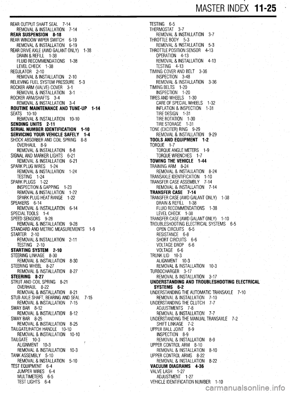
MASTER INDEX 11-25 -
REAROUTPUTSHAFTSEAL 7-14
TESTING 6-5
REMOVAL & INSTALLATION 7-14
' THERMOSTAT 3-7
REAR SUSPENSION 8-18 REMOVAL & INSTALLATION 3-7
REAR WINDOW WIPER SWITCH 6-19 THROTTLE BODY 5-3
REMOVAL&INSTALLATION 6-19 REMOVAL & INSTALLATION 5-3
REARDRlVEAXLE(AWDGALANTONLY) l-38
THROTTLEPOSITIONSENSOR 4-13
DRAIN &REFILL 1-38
OPERATION 4-13
FLUIDRECOMMENDATIONS 1-38 , REMOVAL&INSTALLATION 4-13
LEVELCHECK l-38
TESTING 4-13
REGULATOR 2-10 TIMING COVERAND BELT 3-36
REMOVAL&INSTALLATION 2-10
INSPECTION 3-48
RELIEVING FUELSYSTEM PRESSURE 5-3 REMOVAL & INSTALLATION 3-36
ROCKERARM(VALVE)COVER 3-1
TIMING BELTS l-20
REMOVAL & INSTALLATION 3-1
INSPECTION I-20
ROCKER ARM/SHAFTS 3-4
TIRESANDWHEELS I-30
REMOVAL & INSTALLATION 3-4
CAREOFSPECIALWHEELS l-32
ROUTINE MAINTENANCE AND TUNE-UP 1-14 INFLATION & INSPECTION I-31
SEATS IO-IO
TIRE DESIGN I-31
REMOVAL&INSTALLATION IO-IO TIRE ROTATION I-30
SENDING UNITS 2-11
TIRESTORAGE I-31
SERIAL NUMBER IDENTIFICATION l-10
TONE (EXCITER) RING 9-29
SERVICING YOUR VEHICLE SAFELY I-4
REMOVAL & INSTALLATION 9-29
SHOCKABSORBERAND COILSPRING 8-8
TOOLS AND EQUIPMENT 1-2
OVERHAUL 8-9
TORQUE 1-7
REMOVAL&INSTALLATION 8-8 TORQUEANGLEMETERS l-9
SIGNAL AND MARKER LIGHTS 6-21
TORQUEWRENCHES l-7
REMOVAL & INSTALLATION 6-21
TOWING THE VEHICLE 1-44
SPARKPLUG WIRES 1-24
TRAINING ARM 8-24
REMOVAL&INSTALLATION 1-24
REMOVAL & INSTALLATION 8-24
TESTING 1-24
TRANSAXLEIDENTIFICATION I-10
SPARKPLUGS l-22
TRANSFER CASE ASSEMBLY 7-14
INSPECTION &GAPPING l-23
REMOVAL & INSTALLATION 7-14
REMOVAL&INSTALLATION 1-22
TRANSFER CASE 7-14
SPARKPLUGHEATRANGE 1-22
TRANSFERCASE(AWD GALANT ONLY) 1-38
SPEAKERS 6-14
DRAIN &REFILL 1-38
REMOVAL & INSTALLATION 6-14
FLUIDRECOMMENDATIONS 1-38
SPECIALTOOLS 1-4
LEVELCHECK 1-38
SPEED SENSORS 9-28
TRANSFERCASE(AWDGALANTONLY) I-10
REMOVAL & INSTALLATION 9-28
TROUBLESHOOTING ELECTRICALSYSTEMS 6-5
STANDARDANDMETRIC MEASUREMENTS l-9
OPEN CIRCUITS 6-5
STARTER 2-10
RESISTANCE 6-8
REMOVAL&INSTALLATION 2-11
SHORT CIRCUITS 6-6
TESTING 2-10
VOLTAGEDROP 6-6
STARTING SYSTEM 2-10
VOLTAGE 6-6
STEERING LINKAGE 8-30
TRUNK LID IO-3
REMOVAL &INSTALLATION 8-30
ALIGNMENT IO-3
STEERING WHEEL 8-27
REMOVAL & INSTALLATION IO-3
REMOVAL &INSTALLATION 8-27
TURBOCHARGER 3-17
STEERING 8-27
REMOVAL & INSTALLATION 3-17
STRUT AND COIL SPRING
8-21
UNDERSTANDING AND TROUBLESHOOTING ELECTRICAL
OVERHAUL 8-22
SYSTEMS 6-2
REMOVAL & INSTALLATION 8-21
UNDERSTANDINGTHEAUTOMATICTRANSAXLE 7-10
STUBAXLESHAFT,BEARlNG AND SEAL 7-15
REMOVAL & INSTALLATION 7-10
REMOVAL&INSTALLATION 7-15
UNDERSTANDINGTHECLUTCH 7-7
SWAY BAR 8-12
ADJUSTMENTS 7-8
REMOVAL 8, INSTALLATION 8-12
REMOVAL&INSTALLATION 7-7
SWAY BAR 8-25
UNDERSTANDINGTHE MANUALTRANSAXLE 7-2
REMOVAL&INSTALLATION 8-25
SHIFT LINKAGE 7-2
TAILGATE/HATCH HANDLE lo-19
UPPER BALLJOINT 8-9
REMOVAL &INSTALLATION lo-10
INSPECTION 8-9
TAILGATE IO-3
REMOVAL &INSTALLATION 8-9
ALIGNMENT IO-3 i'
UPPER CONTROLARM 8-10
REMOVAL & INSTALLATION IO-3
REMOVAL & INSTALLATION 8-10
TANKASSEMBLY 5-10
UPPER CONTROL ARMS 8-22
REMOVAL&INSTALLATION 5-10
REMOVAL & INSTALLATION 8-22
TEST EQUIPMENT 6-4
VACUUM DIAGRAMS 4-36
JUMPER WIRES 6-4
VALVE LASH 1-27
MULTIMETERS 6-5
ADJUSTMENT 1-27
TEST LIGHTS 6-4
VEHICLE IDENTIFICATION NUMBER I-10