flat tire MITSUBISHI DIAMANTE 1900 Repair Manual
[x] Cancel search | Manufacturer: MITSUBISHI, Model Year: 1900, Model line: DIAMANTE, Model: MITSUBISHI DIAMANTE 1900Pages: 408, PDF Size: 71.03 MB
Page 1 of 408
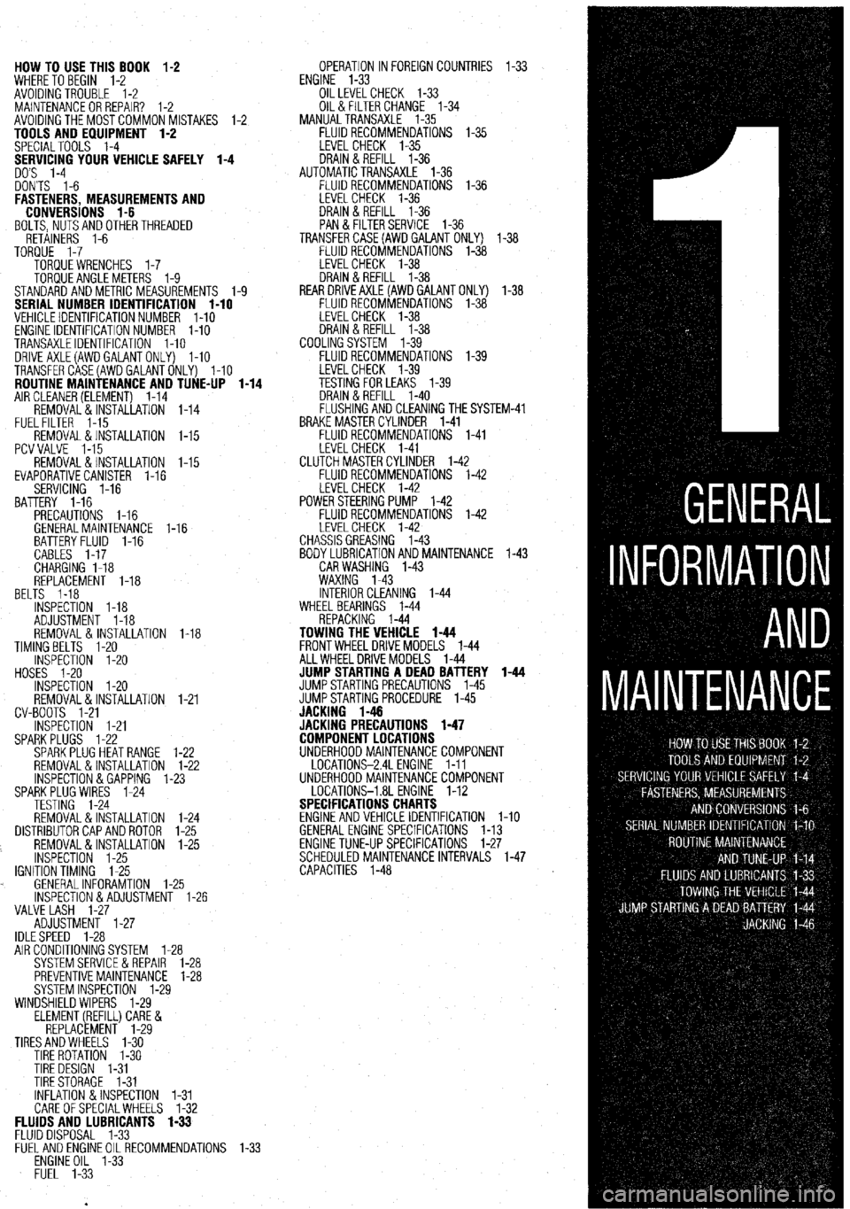
HOW TO USE THIS BOOK 1-2
WHERE TOBEGIN l-2
AVOIDINGTROUBLE 1-2
MAINTENANCEORREPAIR? 1-2
AVOIDINGTHEMOSTCOMMONMISTAKES l-2
TOOLS AND EQUIPMENT 1-2
SPECIALTOOLS l-4
YOUR VEHICLE SAFELY 1-4
DON'TS l-6
FASTENERS, MEASUREMENTS AND
CONVERSIONS l-6
BOLTS,NUTSANDOTHERTHREADED
RETAINERS 1-6
TORQUE l-7
TORQUEWRENCHES l-7
TORQUEANGLEMETERS 1-9
STANDARDANDMETRIC MEASUREMENTS l-9
SERIAL NUMBER IDENTIFICATION l-10
VEHICLE IDENTIFICATION NUMBER l-10
ENGINE IDENTIFICATION NUMBER I-10
TRANSAXLEIDENTIFICATION I-10
DRlVEAXLE(AWDGALANTONLY) l-10
TRANSFERCASE(AWDGALANTONLY) l-10
ROUTINE MAINTENANCE AND TUNE-UP l-14
AIRCLEANER(ELEMENT) 1-14
REMOVAL&INSTALLATION 1-14
FUELFILTER 1-15
REMOVAL &INSTALLATION l-15
PCVVALVE l-15
REMOVAL&INSTALLATION l-15
EVAPORATIVECANISTER l-16
SERVICING 1-16
BATTERY 1-16
PRECAUTIONS I-16
GENERALMAINTENANCE 1-16
BEL BATTERYFLUID 1-16
CABLES I-17
CHARGING I-18
REPLACEMENT 1-18
TS 1-18
INSPECTiON l-18
ADJUSTMENT 1-18
REMOVAL&INSTALLATION 1-18
TIMINGBELTS l-20
INSPECTION l-20
HOSES I-20
INSPECTION l-20
REMOVAL&INSTALLATION
CV-BOOTS 1-21
INSPECTION l-21
SPARKPLUGS l-22
SPARKPLUGHEATRANGE
REMOVAL&INSTALLATION
INSPECTION &GAPPING 1.
SPARKPLUG WIRES 1-24
TESTING 1-24
REMOVAL&INSTALLATION
DISTRIBUTORCAPANDROTOR
REMOVAL&INSTALLATION
INSPECTION 1-25
IGNITIONTIMING 1-25
. GENERALINFORAMTION l-
lNSPECTlON&ADJUSTMENl
VALVE LASH l-27
ADJUSTMENT l-27
IDLESPEED 1-28 1-21
l-22
l-22
-23
1-24
l-25
l-25
.25
1-26
AIR CONDITIONING SYSTEM 1-28
SYSTEMSERVlCEiiREPAlR l-28
PREVENTIVEMAINTENANCE 1-28
SYSTEM INSPECTION l-29
WINDSHIELD WIPERS l-29
ELEMENT(REFILL)CARE&
REPLACEMENT l-29
TIRESANDWHEELS l-30
TIRE ROTATION I-30
TIRE DESIGN 1-31
TIRESTORAGE l-31
INFLATION &INSPECTION l-31
CARE OFSPECIALWHEELS l-32 OPERATION INFOREIGNCOUNTRIES l-33
ENGINE l-33
OILLEVELCHECK 1-33
OIL& FILTER CHANGE l-34
MANUALTRANSAXLE l-35
FLUIDRECOMMENDATIONS l-35
LEVELCHECK l-35
DRAIN&REFILL l-36
AUTOMATICTRANSAXLE l-36
FLUIDRECOMMENDATIONS l-36
LEVELCHECK 1-36
DRAIN&REFILL l-36
PAN & FILTERSERVICE 1-36
TRANSFERCASE(AWDGAlANT ONLY) l-38
FLUIDRECOMMENDATIONS l-38
LEVELCHECK l-38
DRAIN&REFILL l-38
REARDRlVEAXLE(AWDGALANTONLY) l-38
FLUIDRECOMMENDATIONS l-38
LEVELCHECK l-38
DRAIN&REFILL l-38
COOLINGSYSTEM l-39
FLUIDRECOMMENDATIONS l-39
iM-41
FLUIDS AND LUBRICANTS 1-33
FLUID DISPOSAL 1-33
FlJELANDENGlNEOILRECOMMENDATlONS
ENGINE OIL l-33
FUEL l-33
Page 23 of 408
l-24 GENERALINFORMATIONAND MAINTENANCE
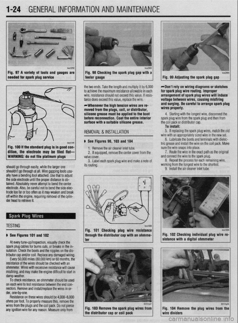
b%slZl2 Fig. 97 A variety of tools and gauges are
needed for spark plug service tm2903 Fig. 98 Checking the spark plug @au with a tccs2904 feeler gauge. - Fig. 99 Adjusting the spark plug gap
ig. 100 If the standard plug Is in good con-
ftlon, the electrode may be filed flat- the two ends. Take the length and multiply it by 6,000
to achieve the maximum resistance allowable in each
wire, resistance should not exceed this value. If resis-
tance does exceed this value, replace the wire.
*Whenever the high tension wires are re- ’
moved from the plugs, coil, or distributor,
silicone grease must be applied to the boot
before reconnection. Coat the entire Interior
surface with a suitable silicone grease.
REMOVAL &INSTALLATION
# See Figures 90,103 and 104
1. Remove the air cleaner inlet tube.
2. If eouiooed, remove the center cover from the
WARNING: do not file platinum plugs
valve covei.
3. Label each spark plug wire and make a note of
should go through easily, while the larger one its routing.
I’ shouldn’t go through at all. Wire gapping tools usu-
ally have a bending tool attached. Use that to adjust
the side electrode until the proper distance is ob-
tained. Absolutely never attempt to bend the center
electrode. Also, be careful not to bend the side elec- *Don’t rely on wiring diagrams or sketches
for spark plug wire routing. Improper
arrangement of spark plug wires will induce
voltage between wires, causing misfiring
and surging. Be careful to arrange spark plug
wires properly.
4. Starting with the longest wire, disconnect the
spark plug wire from the spark plug and then from
the coil pack or distributor cap.
To install:
5. If replacing the spark plug wires, match the olc
wire with an appropriately sized wire in the new set.
6. Lubricate the boots and terminals with dielec-
tric grease and install the wire on the coil pack. Make
sure the wire snaps into place.
a 7. Route the wire in the exact path as the original
nd connect the wire to the spark plug.
8. Repeat the process for each remaining wire,
iorking from the longest wire to the shortest.
9. Install the air cleaner inlet tube.
trode too far or too often as it may weaken and break
off within the engine, requiring removal of the cylin-
der head to retrieve it.
TESTING
# See Figures 191 and 102
At every tune-up/inspection, visually check the
spark plug cables for burns cuts, or breaks in the in-
sulation. Check the boots and the nipples on the dis-
tributor cap and/or coil. Replace any damaged wiring.
Every 50,000 miles (80,000 km) or 60 months, the
resistance of the wires should be checked with an
ohmmeter. Wires with excessive resistance will cause
misfiring, and may make the engine difficult to start in
damp weather.
To check resistance, an ohmmeter should be used ’
on each wire to test resistance between the end con-
nectors. Remove and install/replace the wires in or- ’
der, one-by-one.
Resistance on these wires should be 4,000-6,000
ohms per foot. To properly measure this, remove the
wires from the plugs and the coil pack. Do not pierce
any ignition wire for any reason. Measure only from Fig. 103 Remove the spark plug wires from
tcG1009 Fig. 102 Checking individual plug wire re-
sistance with a digital ohmmeter
Fig. 104 Remove the plug wires from the
wire dividers
Page 29 of 408
.
l-30 GENERAL'INFORMATIONAND MAINTENANCE
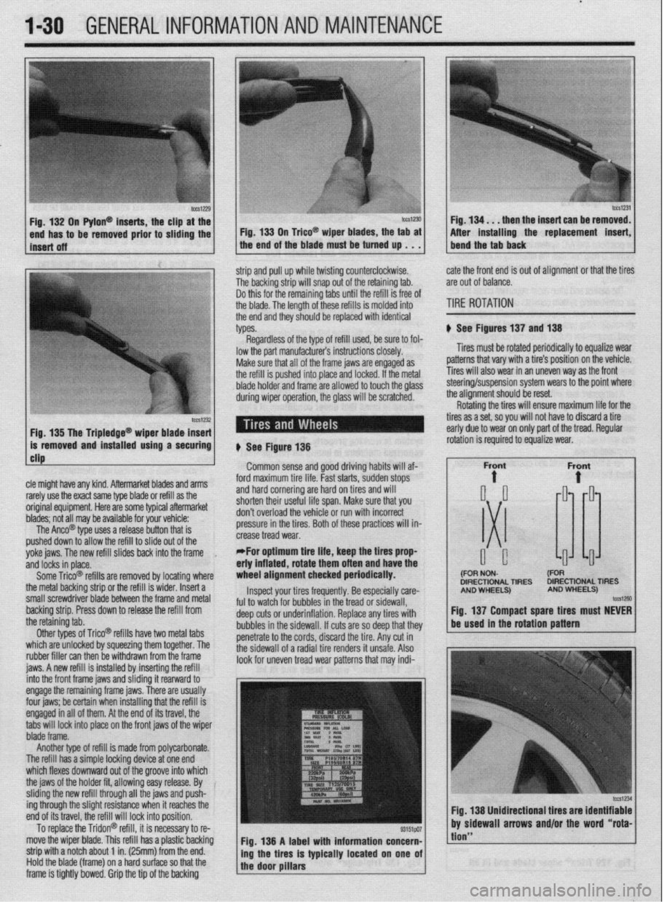
n Pylon@ inserts, the clip
be removed prior to siidi then the insert can be re
After installing the replacement
strip and pull up while twisting counterclockwise.
The backing strip will snap out of the retaining tab.
Do this for the remaining tabs until the refill is free of
the blade. The length of these refills is molded into
the end and they should be replaced with identical
types. cate the front end is out of alignment or that the tires
are out of balance.
TIRE ROTATION
# See Figures 137 and 138
Tires must be rotated periodically to equalize wear
patterns that vary with a tire’s position on the vehicle.
Tires will also wear in an uneven way as the front
1 Fin 1% Tha Trinlarlna@
cle might have any kind. Aftermarket blades and arms
rarely use the exact same type blade or refill as the
original equipment. Here are some typiel aftermarket
blades; not all may be available for your vehicle:
The Anco@ type uses a release button that is
pushed down to allow the refill to slide out of the
yoke jaws. The new refill slides back into the frame
,
and locks in place.
Some Trico@ refills are removed by locating where
the metal backing strip or the refill is wider. Insert a
small screwdriver blade between the frame and metal
backing strip. Press down to release the refill from
the retaining tab.
Other types of Trico@’ refills have two metal tabs
which are unlocked by squeezing them together. The
rubber filler can then be withdrawn from the frame
iaws. A new refill is installed bv insertina the refill lowed to touch the olass steering/suspension system wears to the point where
the alianment should be reset.
# See Figure 138
Common sense and good driving habits will af-
ford maximum tire life. Fast starts, sudden stops
and hard cornering are hard on tires and will
shorten their useful life span. Make sure that you
don’t overload the vehicle or run with incorrect
pressure in the tires. Both of these practices will in-
crease tread wear.
*For optimum tire life, keep the fires prop
eriy inflated, rotate them often and have the
wheel alignment checked periodically.
Inspect your tires frequently. Be especially care-
ful to watch for bubbles in the tread or sidewall,
deep cuts or underinflation. Replace any tires with
bubbles in the sidewall. If cuts are so deep that they
penetrate to the cords, discard the tire. Any cut in
the sidewall of a radial tire renders it unsafe. Also
look for uneven tread wear patterns that may indi- Rotating the tires will ensure maximum life for the
tires as a set, so you will not have to discard a tire
early due to wear on only part of the tread. Regular
DIRECTIONAL TIRES DIRECTIONAL TIRES
jnto the front frame jaws and &ding it rearward to
engage the remaining frame jaws. There are usually
four jaws; be certain when installing that the refill is
engaged in all of them. At the end of its travel, the
tabs will lock into place on the front jaws of the wiper
blade frame.
Another type of refill is made from polycarbonate.
The refill has a simple locking device at one end
which flexes downward out of the groove into which
the jaws of the holder fit, allowing easy release. By
sliding the new refill through all the jaws and push-
ing through the slight resistance when it reaches the
end of its travel, the refill will lock into position.
To replace the Tridon@ refill, it is necessary to re-
move the wiper blade. This refill has a plastic backing
strip with a notch about 1 in. (25mm) from the end.
Hold the blade (frame) on a hard surface so that the
frame is tightly bowed. Grip the tip of the backing Fig. 138 A label with information concern-
ing the tires is typically located on one of
the door pillars
tion”
Page 30 of 408
GENERALINFORMATIONAND MAlNTENANdE 1-31
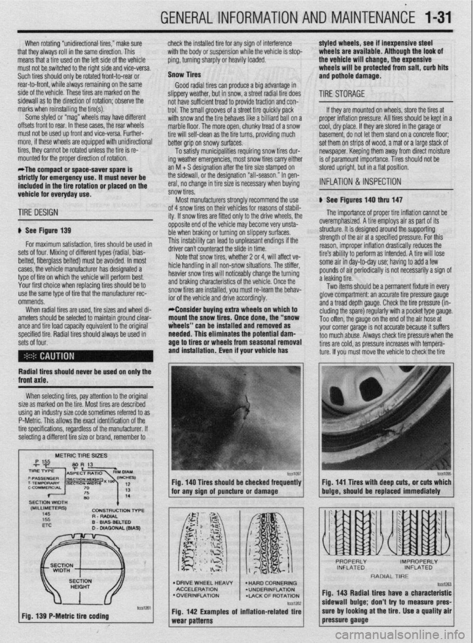
When rotating “unidirectional tires,” make sure
that they always roll in the same direction. This
means that a tire used on the left side of the vehicle
must not be switched to the right side and vice-versa.
Such tires should only be rotated front-to-rear or
rear-to-front, while always remaining on the same
side of the vehicle. These tires are marked on the
sidewall as to the direction of rotation; observe the
marks when reinstalling the tire(s).
Some styled or “mag” wheels may have different
offsets front to rear. In these cases, the rear wheels
must not be used up front and vice-versa. Further-
more, if these wheels are equipped with unidirectional
tires, they cannot be rotated unless the tire is re-
mounted for the proper direction of rotation.
*The compact or space-saver spare is
strictly for emergency use. it must never be
included in the tire rotation or placed on the
vehicle for everyday use. check the installed tire for any sign of interference
with the body or suspension while the vehicle is stop-
ping, turning sharply or heavily loaded.
Snow Tires
Good radial tires can produce a big advantage in
slippery weather, but in snow, a street radial tire does
not have sufficient tread to provide traction and con-
trol. The small grooves of a street tire quickly pack
with snow and the tire behaves like a billiard ball on a
marble floor, The more open, chunky tread of a snow
tire will self-clean as the tire turns, providing much
better grip on snowy surfaces.
To satisfy municipalities requiring snow tires dur-
ing weather emergencies, most snow tires carry either
an M + S designation after the tire size stamped on
the sidewall, or the designation “all-season.” In gen-
eral, no change in tire size is necessary when buying
snow tires.
Most manufacturers stronqlv recommend the use styled wheels, see if inexpensive steel
wheels are available, Although the look of
the vehicle will change, the expensive
wheels will be protected from salt, curb hits
and pothole damage.
TIRESTORAGE
If they are mounted on wheels, store the tires at
proper inflation pressure. All tires should be kept in a
cool, dry place. If they are stored in the garage or
basement, do not let them stand on a concrete floor;
set them on strips of wood, a mat or a large stack of
newspaper. Keeping them away from direct moisture
is of paramount importance. Tires should not be
stored upright, but in a flat position.
INFLATION & INSPECTION
b See Figures 140 thru 147
TIRE DESIGN
p See Figure 139
for maximum satisfaction, tires should be used in
sets of four. Mixing of different types (radial, bias-
belted, fiberglass belted) must be avoided. In most
cases, the vehicle manufacturer has designated a
type of tire on which the vehicle will perform best.
Your first choice when replacing tires should be to
use the same type of tire that the manufacturer rec-
ommends.
When radial tires are used, tire sizes and wheel di-
ameters should be selected to maintain ground clear-
ante and tire load caoacitv eauivalent to the oriainal
specified tire. Radial tiresshould always be used in
sets of four. of 4 snow tires on their
lehicies for reasons of stabil-
ity. If snow tires are fitter
1 only to the drive wheels, the
opposite end of the vehil cle may become very unsta-
ble when braking or turn
ring on slippery surfaces.
This instability can lead to unpleasant endings if the
A*:,,“- r-..l, ^_.. ..& ^_^^, &I.
UIIVU MII I LUUII~~MLL iue slide in time.
Note that snow tires, whether 2 or 4, will affect ve-
hicle handling in all non-snow situations. The stiffer,
heavier snow tires will noticeably change the turning
and braking characteristics of the vehicle. Once the
snow tires are installed, you must re-learn the behav-
ior of the vehicle and drive accordingly.
*Consider buying extra wheels on which to
mount the snow tires. Once done, the “snow
iheeis” can be installed and removed as
needed. This eliminates the potential
dam- age to tires or wheels from seasonal removal
and installation. Even if your vehicle has
lb The importance of proper tire inflation cannot be
overemphasized. A tire employs air as part of its
structure. It is designed around the supporting
strength of the air at a specified pressure. For this
reason, improper inflation drastically reduces the
tire’s ability to perform as intended. A tire will lose
some air in day-to-day use; having to add a few
pounds of air periodically is not necessarily a sign of
a leaking tire.
Two items should be a permanent fixture in every
glove compartment: an accurate tire pressure gauge
and a tread depth gauge. Check the tire pressure (in-
eluding the spare) regularly with a pocket type gauge.
Too often, the gauge on the end of the air hose at
vnr rr corner narane is not accurate because it suffers
~rs check tire oressure when the
Radial tires should never be used on only the
XI I._.
‘-’ --“‘“’ J s too much abuse. Alwa!
tires are cold, as pressure increases with tempera-
ture. If you must move the vehicle to check the tire
front axle.
When selecting tires, pay attention to the original
size as marked on the tire. Most tires are described
using an industry size code sometimes referred to as
P-Metric. This allows the exact identification of the
tire specifications, regardless of the manufacturer. If
selecting a different tire size or brand, remember to
METRIC TIRE SIZES
(MILLIMETERS)
145 CDNStRUCtlDN l-6-E
R - RADIAL
D
WA9
Fig. 139 P-Metric tire coding Fig. 140 Tires should be checked frequently
I I Fig. 141 Tires with deep cuts, or cuts which
for any sion of auncture or damaoe
buioe, should be replaced immediately
l DRIVE WHEEL HEAW
ACCELERATION
l OVERINFLATION
*LACK OF ROTATION
Fig. 142 Examples of inflation-related tire
RADIAL TIRE
fig. 143 Radial tires have a characteristic
sidewall bulge; don’t try to measure pres-
sure by looking at the tire. Use a quality air
pressure gauge
Page 31 of 408
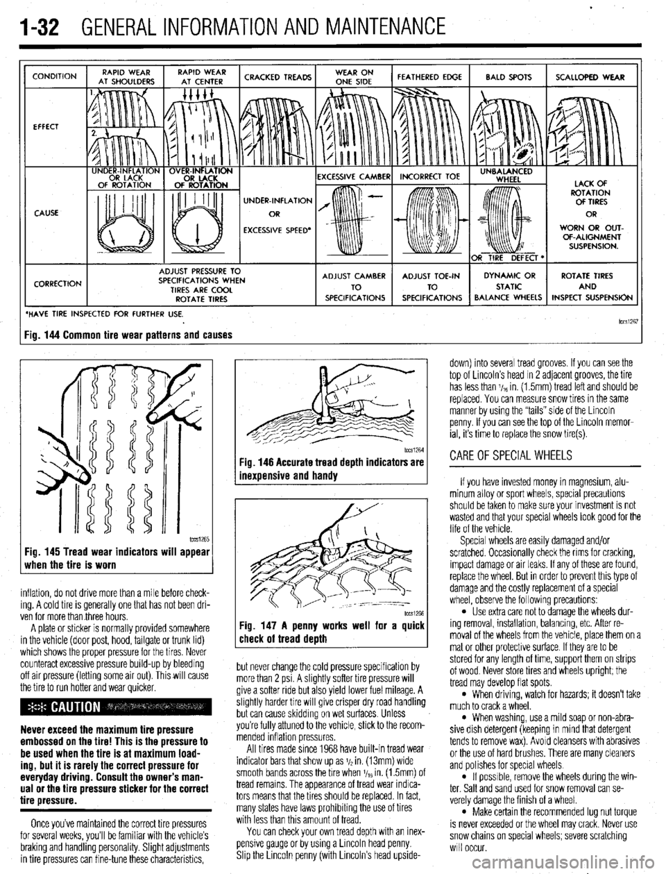
.
1-32 GENERALINFORMATIONAND MAINTENANCE
CONDITION
EFFECT
CAUSE
CORRECTION UNDER-INFLATION
EXCESSIVE SPEED’ WORN OR OUT-
OF-ALIGNMENT
ADJUST PRESSURE TO
SPECIFICATIONS WHEN
TIRES ARE COOL
ROTATE TIRES
/ BALANCE WHEELS INSPECT SUSPENSION
HAVE TIRE INSPECTED FOR FURTHER USE.
lCCSi267 ig. 144 Common tire wear patterns and causes
1~~~1265 Fig. 145 Tread wear indicators will appear
when the tire is worn
inflation, do not drive more than a mile before check-
ing. A cold tire is generally one that has not been dri-
ven for more than three hours.
A plate or sticker is normally provided somewhere
in the vehicle (door post, hood, tailgate or trunk lid)
which shows the proper pressure for the tires. Never
counteract excessive pressure build-up by bleeding
off air pressure (letting some air out). This will cause
the tire to run hotter and wear quicker.
Never exceed the maximum tire pressure
embossed on the tire! This is the pressure to
be used when the tire is at maximum load-
ing, but it is rarely the correct pressure for
everyday driving. Consult the owner’s man-
ual or the tire pressure sticker for the correct
tire pressure.
Once you’ve maintained the correct tire pressures
for several weeks, you’ll be familiar with the vehicle’s
braking and handling personality. Slight adjustments
in tire pressures can fine-tune these characteristics,
1~~~1264 Fig. 146 Accurate tread depth indicators are
inexuensive and handv
Fig. 147 A penny works well for a quick
check of tread death
but never change the cold pressure specification by
more than 2 psi. A slightly softer tire pressure will
give a softer ride but also yield lower fuel mileage. A
slightly harder tire will give crisper dry road handling
but can cause skidding on wet surfaces. Unless
you’re fully attuned to the vehicle, stick to the recom-
mended inflation pressures.
All tires made since 1968 have built-in tread wear
indicator bars that show up as j/2 in. (13mm) wide
smooth bands across the bre when V,~ in. (1.5mm) of
tread remains. The appearance of tread wear indica-
tors means that the tires should be replaced. In fact,
many states have laws prohibiting the use of tires
with less than this amount of tread.
You can check your own tread depth with an inex-
pensive gauge or by using a Lincoln head penny.
Shp the Lrncoln penny (with Lincoln’s head upside- down) into several tread grooves. If you can see the
top of Lincoln’s head in 2 adjacent grooves, the tire
has less than V,~ in. (1.5mm) tread left and should be
replaced. You can measure snow tires in the same
manner by using the “tails” side of the Lincoln
penny. If you can see the top of the Lincoln memor-
ial, its time to replace the snow tire(s).
CAREOFSPECIALWHEELS
If you have invested money in magnesium, alu-
minum alloy or sport wheels, special precautions
should be taken to make sure your investment is not
wasted and that your special wheels look good for the
life of the vehicle.
Special wheels are easily damaged and/or
scratched. Occasionally check the rims for cracking,
impact damage or air leaks. If any of these are found,
replace the wheel. But in order to prevent this type of
damage and the costly replacement of a special
wheel, observe the following precautions:
l Use extra care not to damage the wheels dur-
ing removal, installation, balancing, etc. After re-
moval of the wheels from the vehicle, place them on a
mat or other protective surface. If they are to be
stored for any length of time, support them on strips
of wood. Never store tires and wheels upright; the
tread may develop flat spots.
l When driving, watch for hazards; it doesn’t take
much to crack a wheel.
l When washing, use a mild soap or non-abra-
sive dish detergent (keeping in mind that detergent
tends to remove wax). Avoid cleansers with abrasives
or the use of hard brushes. There are many cleaners
and polishes for special wheels.
l If possrble, remove the wheels during the win-
ter. Salt and sand used for snow removal can se-
verely damage the finish of a wheel.
l Make certain the recommended lug nut torque
is never exceeded or the wheel may crack. Never use
snow chains on special wheels; severe scratching
will occur.
Page 44 of 408
GENERALINFORMATIONAND MAINTENANCE 1-45
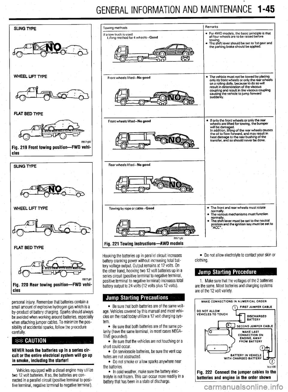
SLING TYPE
WHEEL LIFT TYPE
cles
SUNG TYPE
WHEEL LIFT TYPE
FLAT BED TYPE
Fig. 220 Rear towing position-FWD vehi
cles
personal injury. Remember that batteries contain a
small amount of explosive hydrogen gas which is a
by-product of battery charging. Sparks should always
be avoided when working around batteries, especially
when attaching jumper cables. To minimize the pos-
sibility of accidental sparks, follow the procedure
carefully.
NEVER hook the batteries up in a series cir-
cuit or the entire electrical system will go up
in smoke. includino the starter!
Vehicles equipped with a diesel engine may utilize
two 12 volt batteries. If so, the batteries are con-
nected in a parallel circuit (positive terminal to posi-
tive terminal, negative terminal to negative terminal).
owrng methods
a tow truck IS used
Lrftrng method for 4 wheels-Good
Front wheels lifted-No good
Front wheels lifted-No good
Rear wheels lifted-No good
Towing by rope or cable-Good
e9571g92 qemarks
. For4WD models, the basic principle is that
all four wheels are to be rarsed before
towing.
. The shift lever should be set to 1 st gear and
the parking brake should be applied.
l The vehicle must not be towed by tofacing
only its front wheels or only the rear wheels
on a rollino dollv, because to do so will
result in d&e&ration of the visfx~s
coupling and result in the viscous coupling
causing the vehicle to jump forward
suddenly.
l If only the front wheels or only the rear
wheels are lifted for towing, the bumper
wrll bedamyd.
In addrtron. II trng of the rear wheels causes
the or1 to flow forward. and may result in
heat damage to the rear bushing of the
transfer, and so should never be done.
l The front and rear wheels must rotate
normally.
l The various mechanisms must function
normally.
l The shift lever must be set to the neutral
~Asi&n and the ignition key must be set to
Fig. 221 Towing instructions-AWD models
Hooking the batteries up in parallel circuit increases
battery cranking power without increasing total bat-
tery voltage output. Output remains at 12 volts. On
the other hand, hooking two 12 volt batteries up in a
series circuit (positive terminal to negative terminal,
positive terminal to negative terminal) increases total
battery output to 24 volts (12 volts plus 12 volts).
l Be sure that both batteries are of the same volt-
age. Vehicles covered by this manual and most vehi-
cles on the road today utilize a 12 volt charging sys-
tem.
l Be sure that both batteries are of the same po-
larity (have the same terminal, in most cases NEGA-
TIVE grounded).
l Be sure that the vehicles are not touching or a
short could occur.
l On serviceable batteries, be sure the vent cap
holes are not obstructed.
l Do not smoke or allow sparks anywhere near
the batteries.
l In cold weather, make sure the battery elec-
trolyte is not frozen, This can occur more readily in a
battery that has been in a state of discharge.
l Do not allow electrolyte to contact your skin or
clothing.
1. Make sure that the voltages of the 2 batteries
are the same. Most batteries and charging systems
are of the 12 volt variety.
MAKE CONNECTIONS IN NUMERICAL ORDER
A FIRST JUMPER CABLE
WITH CHARGED BATTERY
-
lccslQ?,Q
Fig. 222 Connect the jumper cables to the
batteries and engine in the order shown
Page 45 of 408
.
I-46 GENERALINFORMATIONAND MAINTENANCE
2. Pull the jumping vehicle (with the good bat-
tery) into a position so the jumper cables can reach
the dead battery and that vehicle’s engine. Make sure
that the vehicles do NOT touch.
3. Place the transmissions/transaxles of both ve-
hicles in Neutral (MT) or P (AT), as applicable, then
firmly set their parking brakes.
*ff necessary for safety reasons, the hazard
lights on both vehicles may be operated
throughout the entire procedure without sig-
nificantiy increasing the diff icuity of jumping
the dead battery.
4. Turn all lights and accessories OFF on both
vehicles. Make sure the ignition switches on both ve-
hicles are turned to the OFF position.
5. Cover the battery cell caps with a rag, but do
not cover the terminals.
6. Make sure the terminals on both batteries are
clean and free of corrosion or proper electrical con-
nection will be impeded. If necessary, clean the bat-
tery terminals before proceeding.
7. Identify the positive (+) and negative (-) termi-
nals on both batteries.
8. Connect the first jumper cable to the positive
(t) terminal of the dead battery, then connect the
other end of that cable to the positive (t) terminal of
the booster (good) battery.
9. Connect one end of the other jumper cable to
the negative (−) terminal on the booster bat-
tery and the final cable clamp to an engine bolt head,
alternator bracket or other solid, metallic point on the
engine with the dead battery. Try to pick a ground on
the engine that is positioned away from the battery in
order to minimize the possibility of the 2 clamps
touching should one loosen during the procedure.
DO NOT connect this clamp to the negative (-) termi-
nal of the bad battery. cable on the donor battery. Disconnect the positive
cable from the donor battery and finally, disconnect
the positive cable from the formerly dead battery. Be
careful when disconnecting the cables from the posi-
tive terminals not to allow the alligator clips to touch
any metal on either vehicle or a short and sparks will
occur.
I
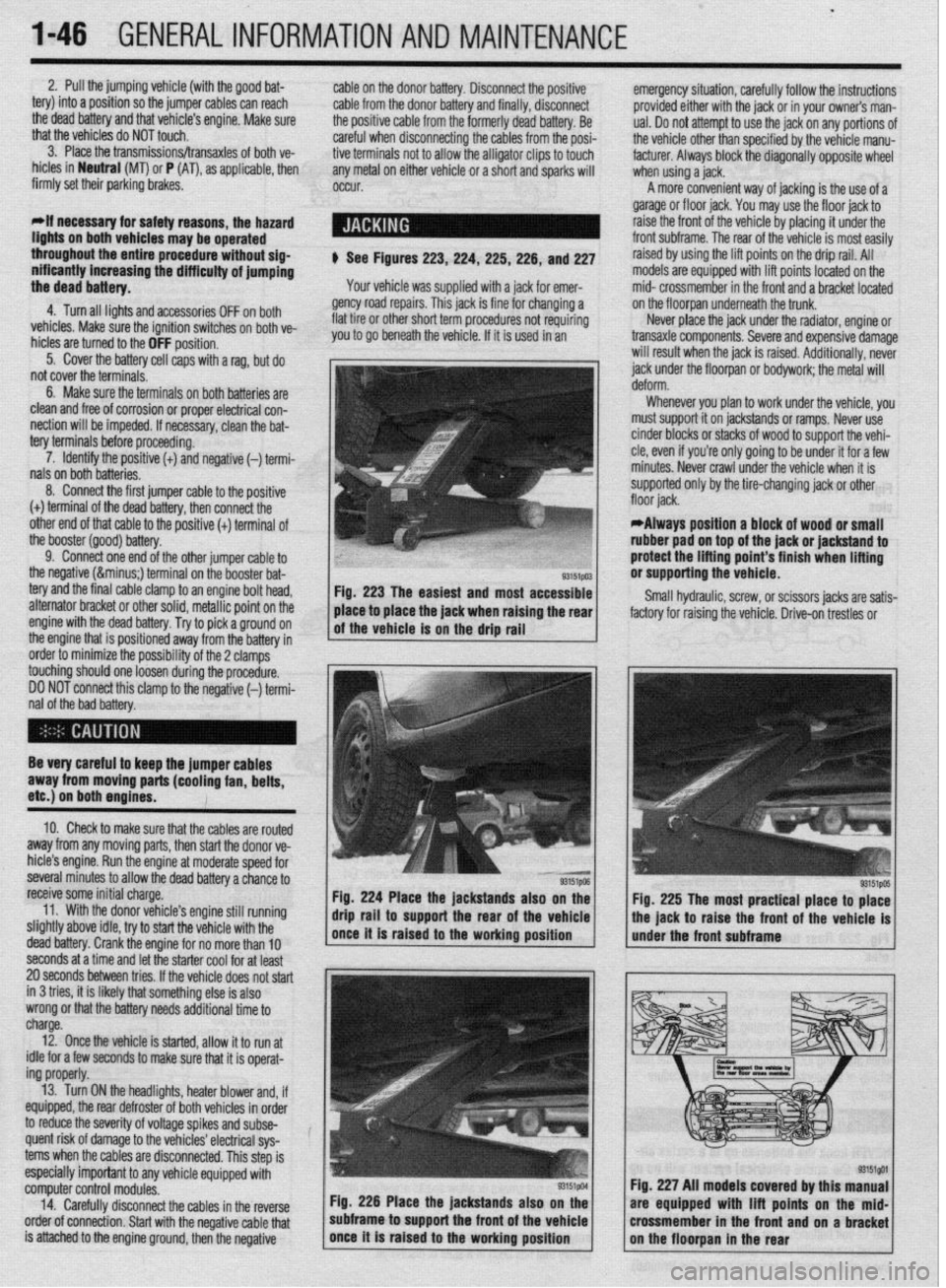
$ See Figures 223,224, 225,226, and 227
Your vehicle was supplied with a jack for emer-
gency road repairs. This jack is fine for changing a
flat tire or other short term procedures not requiring
you to go beneath the vehicle. If it is used in an emergency situation, carefully follow the instructions
provided either with the jack or in your owners man-
ual. Do not attempt to use the jack on any portions of
the vehicle other than specified by the vehicle manu-
facturer. Always block the diagonally opposite wheel
when using a jack.
A more convenient way of jacking is the use of a
garage or floor jack. You may use the floor jack to
raise the front of the vehicle by placing it under the
front subframe. The rear of the vehicle is most easily
raised by using the lift points on the drip rail. All
models are equipped with lift points located on the
mid- crossmember in the front and a bracket located
on the floorpan underneath the trunk.
Never place the jack under the radiator, engine or
transaxle components. Severe and expensive damage
will result when the jack is raised. Additionally, never
jack under the floorpan or
bodywork; the
metal will
Whenever you plan to work under the vehicle, you
must support it on jackstands or ramps. Never use
cinder blocks or stacks of wood to support the vehi-
cle, even if you’re only going to be under it for a few
minutes. Never crawl under the vehicle when it is
supported only by the tire-changing jack or other
*Always position a block of wood or small
rubber pad on top of the jack or jackstand to
protect the lifting point’s finish when lifting
or supporting the vehicle.
Small hydraulic, screw, or scissors jacks are satis-
factory for raising the vehicle. Drive-on trestles or
Be very careful to keep the jumper cables
away from moving parts (cooling fan, belts,
etc.) on both engines.
10. Check to make sure that the cables are routed
away from any moving parts, then start the donor ve-
hicle’s engine. Run the engine at moderate speed for
several minutes to allow the dead battery a chance to
receive some initial charge.
11. With the donor vehicle’s engine still running
slightly above idle, try to start the vehicle with the
dead battery. Crank the engine for no more than 10 &stands also on the
Fig. 225 The most practical place to place
front of the vehicle is
seconds at a time and let the starter cool for at least
20 seconds between tries. If the vehicle does not start
in 3 tries, it is likely thatsomething else is also
wrong or that the battery needs additional time to
charge.
12. Once the vehicle is started, allow it to run at
idle for a few seconds to make sure that it is operat-
ing properly.
13. Turn ON the headlights, heater blower and, if
equipped, the rear defroster of both vehicles in order
to reduce the severity of voltage spikes and subse-
quent risk of damage to the vehicles’ electrical sys-
tems when the cables are disconnected. This step is
especially important to any vehicle equipped with
computer control modules.
14. Carefully disconnect the cables in the’reverse
order of connection. Start with the negative cable that
is attached to the engine ground, then the negative Fig. 226 Place the jackstands also
subframe to support the front of the Fig. 227 All models covered by this
are equipped with lift points on t
crossmember in the front and on a
Page 127 of 408
3-66 ENGINEANDENGINEOVERHAUL
should be performed on all of the components, but
just because you don’t see a crack does not mean it
is not there. Some more reliable methods for inspect-
ing for cracks include Magnaflux? a magnetic
process or Zyglo@‘, a dye penetrant. Magnaflux@ is
used only on ferrous metal (cast iron). Zyglo@ uses a
spray on fluorescent mixture along with a black light
to reveal the cracks. It is strongly recommended to
have your engine block checked professionally for
cracks, especially if the engine was known to have
overheated and/or leaked or consumed coolant. Con-
tact a local shop for availability and pricing of these
services.
Engine Block
ENGINE BLOCK BEARING ALIGNMENT
Remove the main bearing caps and, if still in:
stalled, the main bearing inserts. Inspect all of the
main bearing saddles and caps for damage, burrs or
high spots. If damage is found, and it is caused from
a spun main bearing, the block will need to be align-
bored or, if severe enough, replacement. Any burrs or
high spots should be carefully removed with a metal
file.
Place a straightedge on the bearing saddles, in the
engine block, along the centerline of the crankshaft. If
any clearance exists between the straightedge and the
saddles, the block must be align-bored.
Align-boring consists of machining the main
bearing saddles and caps by means of a flycutter that
runs through the bearing saddles.
DECK FLATNESS
The top of the engine block where the cylinder
head mounts is called the deck. Insure that the deck
surface is clean of dirt, carbon deposits and old gas-
ket material. Place a straightedge across the surface
of the deck along its centerline and, using feeler
gauges, check the clearance along several points. Re-
peat the checking procedure with the straightedge
placed along both diagonals of the deck surface. If
the reading exceeds 0.003 in. (0.076mm) within a 6.0
in. (152cm) span, or 0.006 in. (0.152mm) over the
total length of the deck, it must be machined.
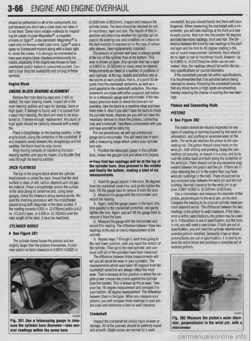
CYLINDER BORES
$ See Figure 261
The cylinder bores house the pistons and are
slightly larger than the pistons themselves. A com-
mon piston-to-bore clearance is 0.0015-0.0025 in. (0.0381mm-O.0635mm). Inspect and measure the
cylinder bores. The bore should be checked for out-
of-roundness, taper and size. The results of this in-
spection will determine whether thecylinder can be
used in its existing size and condition, or a rebore to
the next oversize is required (or in the case of remov-
able sleeves, have replacements installed).
The amount of cylinder wall wear is always greater
at the top of the cylinder than at the bottom. This
wear is known as taper. Any cylinder that has a taper
of 0.0012 in. (0.305mm) or more, must be rebored.
Measurements are taken at a number of positions in
each cylinder: at the top, middle and bottom and at
two points at each position; that is, at a point 90 de-
grees from the crankshaft centerline, as well as a
point parallel to the crankshaft centerline. The mea-
surements are made with either a special dial indica-
tor or a telescopic gauge and micrometer. If the nec-
essary precision tools to check the bore are not
available, take the block to a machine shop and have
them mike it. Also if you don’t have the tools to check
the cylinder bores, chances are you will not have the
necessary devices to check the pistons, connecting
rods and crankshaft. Take these components with you
and save yourself an extra trip.
For our procedures, we will use a telescopic
gauge and a micrometer. You will need one of each,’
with a measuring range which covers your cylinder
bore size.
1, Position the telescopic gauge in the cylinder
bore, loosen the gauges lock and allow it to expand.
*Your first two readings will be at the top of
the cylinder bore, then proceed to the middle
and finally the bottom, making a total of six
measurements.
2. Hold the gauge square in the bore, 90 degrees
from the crankshaft centerline, and gently tighten the
lock. Tilt the gauge back to remove it from the bore.
3. Measure the gauge with the micrometer and
record the reading.
4. Again, hold the gauge square in the bore, this
time parallel to the crankshaft centerline, and gently
tighten the lock. Again, you will tilt the gauge back to
remove it from the bore.
5. Measure the gauge with the micrometer and
record this reading. The difference between these two
readings is the out-of-round measurement of the
cylinder.
6. Repeat steps 1 through 5, each time going to
the next lower position, until you reach the bottom of
the cylinder. Then go to the next cylinder, and con-
tinue until all of the cylinders have been measured.
The difference between these measurements will
tell you all about the wear in your cylinders. The
measurements which were taken 90 degrees from the
crankshaft centerline will always reflect the most
wear.,That is because at this position is where the en-
gine power presses the piston against the cylinder
bore the hardest. This is known as thrust wear. Take
your top, 90 degree measurement and compare it to
your bottom, 90 degree measurement. The difference
between them is the taper. When you measure your
pistons, you will compare these readings to your pis-
ton sizes and determine piston-to-wall clearance. crankshaft, but you should hardly feel them with your
fingernail. When measuring the crankshaft with a mi-
crometer, you will take readings at the front and rear
of each journal, then turn the micrometer 90 degrees
and take two more readings, front and rear. The dif-
ference between the front-to-rear readings is the jour-
nal taper and the first-to-90 degree reading is the
out-of-round measurement. Generally, there should
be no taper or out-of-roundness found, however, up
to 0.0005 in. (0.0127mm) for either can be over-
looked. Also, the readings should fall within the fac-
tory specifications for journal diameters.
If the crankshaft journals fall within specifications,
it is recommended that it be polished before being
returned to service. Polishing the crankshaft insures
that any minor burrs or high spots are smoothed,
thereby reducing the chance of scoring the new bear-
ings.
Pistons and Connecting Rods
PISTONS
N See Figure 262
The piston should be visually inspected for any
signs of cracking or burning (caused by hot spots or
detonation), and scuffing or excessive wear on the
skirts. The wrist pin attaches the piston to the con-
netting rod. The piston should move freely on the
wrist pin, both sliding and pivoting. Grasp the con-
netting rod securely, or mount it in a vise, and try to
rock the piston back and forth along the centerline of
the wrist pin. There should not be any excessive play
evident between the piston and the pin. If there are C-
clips retaining the pin in the piston then you have
wrist pin bushings in the rods. There should not be
any excessive play between the wrist pin and the rod
bushing. Normal clearance for the wrist pin is ap-
prox. 0.001-0.002 in. (0.025mm-0.051mm).
Use a micrometer and measure the diameter of the
piston, perpendicular to the wrist pin, on the skirt.
Compare the reading to its original cylinder measure-
ment obtained earlier. The difference between the two
readings is the piston-to-wall clearance. If the clear-
ante is within specifications, the piston may be used
as is. If the piston is out of specification, but the bore
is not, you will need a new piston. If both are out of
specification, you will need the cylinder rebored and
oversize pistons installed. Generally if two or more
pistons/bores are out of specification, it is best to re-
bore the entire block and purchase a complete set of
oversize pistons.
Crankshaft
Inspect the crankshaft for visible signs of wear or
damage. All of the journals should be perfectly round
and smooth. Slight scores are normal for a used
Page 214 of 408
CHASSIS ELECTRICAL 6-11
45. Install the heater hoses under the hood.
46. Install the mstrument panel by reversing its
removal procedure.
47. Install the center console.
48. install the upper and lower steering column
covers.
49. Install the center panel undercover.
50. Install the small column panel.
51. Install the steering wheel.
52. Fill the cooling system.
53. Connect the negative battery cable and check
the entire climate control system for proper operation
and leaks.
Mirage
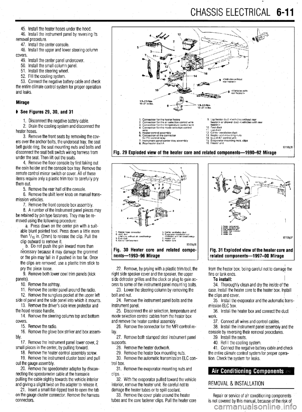
# See Figures 29, 30, and 31
1. Disconnect the negative battery cable.
2. Drain the cooling system and disconnect the
heater hoses.
3. Remove the front seats by removing the cov-
ers over the anchor bolts, the underseat tray, the seat
belt guide ring, the seat mounting nuts and bolts and
disconnect the seat belt switch wiring harness from
under the seat. Then lift out the seats
4. Remove the floor console by first taking out
the coin holder and the console box tray. Remove the
remote control mirror switch or cover. All of these
items require only a plastic trim tool to carefully pry
them out.
5. Remove the rear half of the console.
6. Remove the shift lever knob on manual trans-
mission vehicles.
7. Remove the front console box assembly.
8. A number of the instrument panel pieces may
be retamed by pin type fasteners. They may be re-
moved using the following procedure:
a. Press down on the center pin with a suit-
able blunt pointed tool. Press down a little more
than l/re in. (2mm) to release the clip. Pull the
clip outward to remove it.
b. Do not oush the oin inward more than
necessary because it may damage the grommet
or the pin may fall in if pushed in too far. Once
the clips are removed, use a plastic trim stick to
pry the piece loose.
9. Remove both lower cowl trim panels (kick
panels).
10. Remove the ashtray.
11. Remove the center panel around the radio.
12. Remove the sunglass pocket at the upper left
side of panel and the side panel into which it mounts,
13. Remove the drivers side knee protector and
the hood release handle.
14. Remove the steering column top and bottom
covers.
15. Remove the radio.
16. Remove the glove box striker and box assem-
bly.
17. Remove the instrument panel lower cover, 2
small pieces in the center, by pulling forward.
18. Remove the heater control assembly screw.
19. Remove the instrument cluster bezel and pull
out the Qauge assembly.
20. Remove the speedometer adapter by discon-
necting the speedometer cable at the transaxle
pulling the cable Sightly towards the vehicle interior
and giving a Slight twist on the adapter to release it.
21. Insert a small flat-tipped tool to open the tab
on the QauQe cluster connector. Remove the harness
connectors.
Fig. 29 Exploded view of the heater core and related components-1990-92 Mirage
93l%Q% Fig. 30 Heater core and related compo-
nents-1993-96 Mirage
22. Remove, by prying with a plastic trim tool, the
right side speaker cover and the speaker, the upper
side defroster grilles and the clock or plug to gain ac-
cess to some of the instrument panel mounting bolts.
23. Lower the steering column by removing the
bolt and nut.
24. Remove the instrument panel bolts and the
instrument panel.
25 Drsconnect the air selection, temperature and
mode selection control cables from the heater box
and remove the heater control assembly.
26. Remove the connector for the MFI control re-
lay.
27. Remove both stamped steel instrument panel
supports.
28. Remove the heater ductwork.
29. Remove the heater box mounting nuts.
30 Remove the automatic transmission ELC con-
trol box.
31. Remove the evaporator mounting nuts and
clips.
32. With the evaporator pulled toward the vehicle
interior, remove the heater unit. Be careful not to
damage the heater tubes or to spill coolant.
33. Remove the cover plate around the heater
tubes and the core fastener clips. Pull the heater core 34. Thoroughly clean and dry the inside of the
case. Install the heater core to the heater box. Install
the clips and cover,
35. Install the evaporator and the automatic trans-
mission ELC box.
36. Install the heater box and connect the duct
Fig. 31 Exploded view of the heater core and
related components-1997-00 Mirage
from the heater box, being careful not to damage the
fins or tank ends.
To install: I
work.
37. Connect all wires and control cables,
38. Install the instrument panel assembly and the
console by reversmg their removal procedures.
39 Install the seats.
40. Refill the cooling system.
41. Connect the negative battery cable and check
the entire climate control system for proper opera-
tion Check the system for leaks.
REMOVAL &INSTALLATION
Repair or service of air Conditioning components
is not covered by this manual, because of the risk of
Page 294 of 408
DRIVETRAiN 7-15
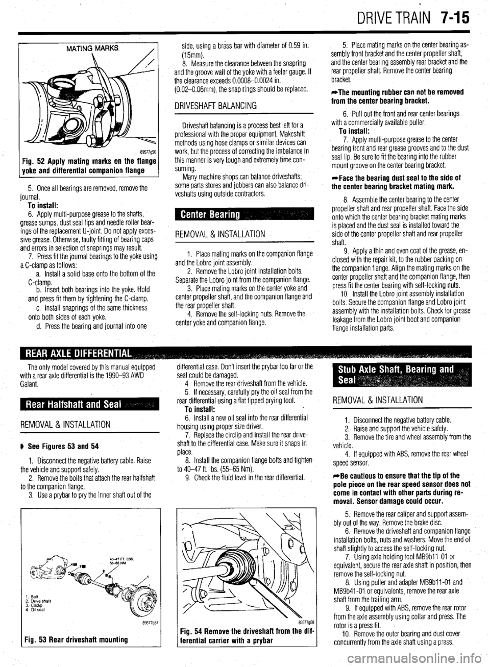
MATING MARKS
/
89577Q5E Fig. 52 Apply mating marks on the flange
yoke and differential companion flange
5. Once all bearings are removed, remove the
journal.
To install:
6. Apply multi-purpose grease to the shafts,
grease sumps, dust seal lips and needle roller bear-
ings of the replacement U-joint Do not apply exces-
sive grease Otherwse, faulty fitting of bearing caps
and errors in selection of snaprings may result.
7. Press fit the journal bearings to the yoke using
a C-clamp as follows:
a. Install a solid base onto the bottom of the
C-clamp.
b. Insert both bearings into the yoke. Hold
and press fit them by tightening the C-clamp.
c. Install snaprings of the same thickness
onto both sides of each yoke.
d. Press the bearing and journal into one side, using a brass bar with diameter of 0.59 in.
(15mm).
8. Measure the clearance between the snapring
and the groove wall of the yoke with a feeler gauge. If
the clearance exceeds 0.0008-0.0024 in.
(0.02-O.O6mm), the snap rings should be replaced.
DRIVESHAFT BALANCING
Driveshaft balancing is a process best left for a
professional wrth the proper equipment. Makeshift
methods using hose clamps or similar devices can
work, but the process of correcting the imbalance in
this manner is very tough and extremely time con-
suming.
Many machine shops can balance driveshafts;
some parts stores and jobbers can also balance dri-
veshafts using outside contractors.
REMOVAL&INSTALLATION
1. Place matmg marks on the companron flange
and the Lobro joint assembly
2. Remove the Lobro joint installation bolts.
Separate the Lobro joint from the companion flange.
3. Place mating marks on the center yoke and
center propeller shaft, and the companion flange and
the rear propeller shaft.
4. Remove the self-locking nuts. Remove the
center yoke and companion flange. 5. Place mating marks on the center bearing as-
sembly front bracket and the center propeller shaft,
and the center bearing assembly rear bracket and the
rear propeller shaft. Remove the center bearing
bracket.
*The mounting rubber can not be removed
from the center bearing bracket.
6. Pull out the front and rear center bearings
with a commercially available puller
To install:
7. Apply multi-purpose grease to the center
bearing front and rear grease grooves and to the dust
seal lip Be sure to fit the bearing into the rubber
mount groove on the center bearing bracket.
*Face the bearing dust seal to the side of
the center bearing bracket mating mark.
8. Assemble the center bearing to the center
propeller shaft and rear propeller shaft. Face the side
onto which the center bearing bracket mating marks
IS placed and the dust seal is installed toward the
side of the center propeller shaft and rear propeller
shaft.
9 Apply a thin and even coat of the grease, en-
closed with the repair kit, to the rubber packing on
the companion flange. Align the mating marks on the
center propeller shaft and the companion flange, then
press fit the center bearing with self-locking nuts.
10 Install the Lobro joint assembly installation
bolts. Secure the companron flange and Lobro joint
assembly with the installation bolts Check for grease
leakage from the Lobro joint boot and companion
flange installabon parts.
The only model covered by this manual equipped
with a rear axle differential is the 1990-93 AWD
Galant.
REMOVAL &INSTALLATION
# See Figures 53 and 54
1. Disconnect the negative battery cable. Raise
the vehicle and support safely.
2. Remove the bolts that attach the rear halfshaft
to the comoanion flanae.
3. Use’a prybar topry the inner shaft out of the
I Fig. 53 Rear driveshaft mounting
89577g5
differential case. Don’t insert the prybar too far or the
seal could be damaged.
4 Remove the rear driveshaft from the vehicle.
5. If necessary, carefully pry the oil seal from the
rear differential using a flat tipped prying tool.
To install:
6. Install a new oil seal into the rear differential
housing using proper size driver.
7. Replace the circlip and install the rear drive-
shaft to the differential case. Make sure it snaps in
place.
8. Install the companion flange bolts and tighten
to 40-47 ft. Ibs. (55-65 Nm).
9. Check the fluid level in the rear differential.
69577958 Fig. 54 Remove the driveshaft from the dif-
ferential carrier with a prybar
REMOVAL &INSTALLATION
1. Disconnect the negative battery cable.
2. Raise and support the vehicle safely.
3 Remove the tire and wheel assembly from the
vehicle.
4 If equipped with ABS, remove the rear wheel
speed sensor.
*Be cautious to ensure that the tip of the
pole piece on the rear speed sensor does not
come in contact with other parts during re-
moval. Sensor damage could occur.
5. Remove the rear caliper and support assem-
bly out of the way. Remove the brake disc.
6. Remove the driveshaft and companion flange
installation bolts, nuts and washers. Move the end of
shaft slightly to access the self-locking nut.
7. Using axle holding tool MBSbll-01 or
equivalent, secure the rear axle shaft in position, then
remove the self-locking nut.
8. Using puller and adapter MBSbll-01 and
MB9b41-01 or equivalents, remove the rear axle
shaft from the trailing arm
9. If equipped with ABS, remove the rear rotor
from the axle assembly using collar and press. The
rotor is a press fit.
10 Remove the outer bearing and dust cover
concurrently from the axle shaft using a press.