remove seats MITSUBISHI DIAMANTE 1900 Repair Manual
[x] Cancel search | Manufacturer: MITSUBISHI, Model Year: 1900, Model line: DIAMANTE, Model: MITSUBISHI DIAMANTE 1900Pages: 408, PDF Size: 71.03 MB
Page 68 of 408
ENGINEANDENGINEOVERHAUL 3-7
4. Remove the center cover, breather and PCV
hoses, and spark plug cables.
5. Remove the rocker cover.
6. Remove the throttle body stay, both camshaft
sprockets, and oil seals.
7. Remove the Camshaft Position fCMP) sensor 3. install the lash adjuster clips on the rocker
arms, then loosen the bearing cap bolts. Do not re-
move the bolts from the bearing caps.
4. Remove the rocker arms, shafts and bearing
caps as an assembly.
lo hlstall: unless it is contaminated or is several years old.
3. Remove any necessary components to access
the thermostat.
4. Remove the thermostat housinq retaininq
nd adapter from the rear of the camshah. ’
8. Remove the intake and exhaust camshafts.
9. Remove rocker arms and lash adjusters from
he head. It is recommended that all lash adjusters
md rockers be replaced as a complete set.
To Install:
10. Immerse the lash adjusters in clean diesel
uel. Using a small wire, move the plunger of the lash
tdjuster up and down four or five times while push-
ng down lightly on the check ball in order to bleed
jut the air. Lubricate and install the lash adjusters in
he cylinder head.
11. Lubricate the camshafts with clean enqine oil
nd position the camshafts on the cylinder head.
12. Install the bearing caps. Tighten the caps in
sequence, in 2 or 3 steps. Caps 2,3 and 4 have a
ront mark. Install with the mark aligned with the front
nark on the cylinder head. Intake caps have I
stamped on the cap and exhaust caps have E. Also,
)e sure the rocker arm is correctly mounted on the
ash adjuster and the valve stem end. Torque the front
md rear retaining cap bolts to 14 ft. Ibs. (20 Nm) and
ighten the center 3 retaining cap bolts to 8 ft. Ibs.
11 Nm).
13. Apply a coating of engine oil to the oil seals
md install.
14. Install the timing belt, valve cover and all re-
ated parts. Refer to the timing belt procedure in this
;ection. 5. Install the bearing caps/rocker arm assem-
blies. Tighten the bolts to 23 ft. Ibs. (31 Nm).
6. Remove the lash adjuster clips.
7. Install the rocker arm cover using a new gas-
ket.
8. Connect the negative battery cable.
REMOVAL &INSTALLATION
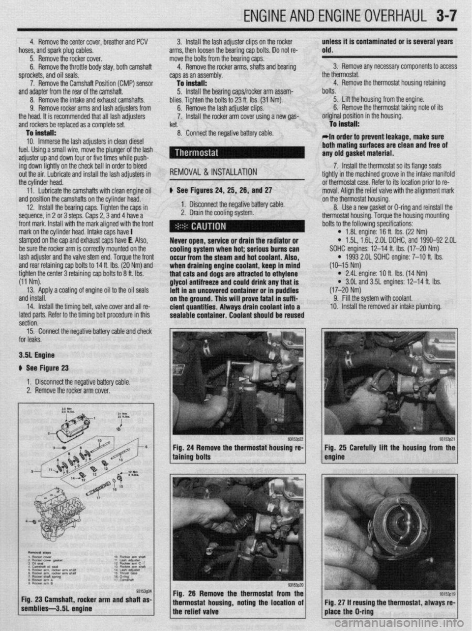
b See Figures 24, 25, 26, and 27
1. Disconnect the negative battery cable.
2. Drain the cooling system.
Never open, service or drain the radiator or
cooling system when hot; serious bums can
occur from the
steam and hot coolant. Also,
when draining engine coolant, keep in mind
that cats and dogs are attracted to ethylene
glycol antifreeze and could drink any that is
left in an uncovered container or in puddles
on the ground. This will prove fatal in suffi-
cient quantities. Always drain coolant into a
sealable container. Coolant should be reused bolts.
5. Lift the housing from the engine.
6. Remove the thermostat taking note of its
original position in the housing.
To Install:
*In order to prevent leakage, make sure
both mating
surfaces are clean and free of
any old gasket material.
7. Install the thermostat so its flange seats
tightly in the machined groove in the intake manifold
or thermostat case. Refer to its location prior to re-
moval. Aliqn the relief valve with the alignment mark
on the thermostat housing.
8. Use a new gasket or D-ring and reinstall the
thermostat housing. Torque the housing mounting
bolts to the following specifications:
l 1.8L engine: 16 ft. Ibs. (22 Nm) l 1.5L, 1.61, 2.OL DOHC, and 1990-92 2.OL
SOHC engines: 12-14 ft. Ibs. (17-20 Nm)
l 1993 2.01 SOHC engine: 7-10 ft. Ibs.
(10-15 Nm)
l 2.4L engine: IO ft. Ibs. (14 Nm) l 3.OL and 3.5L engines: 12-14 ft. Ibs.
(17-20 Nm)
9. Fill the system with coolant.
10. Install the removed air intake plumbing.
15. Connect the negative battery cable and check
or leaks.
3.51 Engine
I See Figure 23
1. Disconnect the negative battery cable.
2. Remove the rocker arm cover.
g. 26 Remove the thermostat from the
ousing, noting the location of using the thermostat, always re-
Page 118 of 408
ENGINEANDENGINEOVERHAUL 3-57
Anything that generates heat and/or friction WIII
eventually burn or wear out (for example, a light bulb
generates heat, therefore its life span is limited). With
this in mind, a running engine generates tremendous
amounts of both; friction is encountered by the mov-
ing and rotating parts inside the engine and heat is
created by friction and combustion of the fuel How-
ever, the engine has systems designed to help reduce
the effects of heat and friction and provide added
longevrty. The oiling system reduces the amount of
friction encountered by the moving parts inside the
engine, while the cooling system reduces heat cre-
ated by friction and combustion If either system is
not maintained, a break-down will be inevitable.
Therefore, you can see how regular maintenance can
affect the service life of your vehicle, If you do not
drain, flush and refill your cooling system at the
proper intervals, deposits WIII begin to accumulate in
the radiator, thereby reducing the amount of heat it
can extract from the coolant The same applies to
your oil and filter; If it is not changed often enough it
becomes laden with contaminates and is unable to
properly lubricate the engine. This increases friction
and wear.
There are a number of methods for evaluating the
condition of your engine. A compression test can re-
veal the condition of your pistons, piston rings,
cylinder bores, head gasket(s), valves and valve
seats. An oil pressure test can warn you of possible
engine bearing, or oil pump failures. Excessrve oil
consumption, evidence of oil in the engine air intake
area and/or bluish smoke from the tailpipe may indi-
cate worn piston rings, worn valve guides and/or
valve seals. As a general rule, an engine that uses no
more than one quart of oil every 1000 miles is in
good condition. Engines that use one quart of oil or
more in less than 1000 miles should first be checked
for oil leaks. If any oil leaks are present, have them
fixed before determining how much oil is consumed
by the engine, especrally if blue smoke is not visible
at the tailpipe
COMPRESSION TEST
# See Figure 226
tccs3801 Fig. 226 A screw-in type compression gauge
is more accurate and easier to use without
an assistant
A noticeable lack of engine power, excessive oil
consumption and/or poor fuel mileage measured
over an extended period are all indicators of internal
engine wear. Worn piston rings, scored or worn
cylinder bores, blown head gaskets, sticking or burnt
valves, and worn valve seats are all possible culprits.
A check of each cylinders compression WIII help lo-
cate the problem.
*A screw-in type compression gauge is
more accurate than the type you simply hold
against the spark plug hole. Although it takes
slightly longer to use, it’s worth the effort to
obtain a more accurate reading.
1 Make sure that the proper amount and vis-
cosity of engine oil is in the crankcase, then ensure
the battery is fully charged.
2. Warm-up the engine to normal operating
temperature, then shut the engine
OFF. 3. Disable the ignition system.
4. Label and disconnect all of the spark plug
wires from the plugs,
5. Thoroughly clean the cylinder head area
around the spark plug ports, then remove the spark
plugs.
6. Set the throttle plate to the fully open (wide-
open throttle) position You can block the accelerator
linkage open for this, or you can have an assistant
fully depress the accelerator pedal.
7. Install a screw-in type compression gauge
into the No. 1 spark plug hole until the fitting is snug.
Be careful not to crossthread the spark plug
hole.
8. According to the tool manufacturers instruc-
tions, connect a remote starting switch to the starting
circuit.
9. With the ignition switch in the
OFF position,
use the remote starting switch to crank the engine
through at least five compression strokes (approxi-
mately 5 seconds of cranking) and record the highest
reading on the gauge
10. Repeat the test on each cylinder, cranking the
engine approximately the same number of compres-
sion strokes and/or time as the first.
11. Compare the hrghest readings from each
cylinder to that of the others. The indicated compres-
sion pressures are considered within specifications if
the lowest reading cylinder is within 75 percent of the
pressure recorded for the highest reading cylinder
For example, if your highest reading cylinder pres-
sure was 150 psi (1034 kPa), then 75 percent of that
would be 113 psi (779 kPa). So the lowest reading
cylinder should be no less than 113 psi (779 kPa).
12. If a cylinder exhibits an unusually low com-
pression reading, pour a tablespoon of clean engine
oil into the cylinder through the spark plug hole and
repeat the compression test. If the compression rises
after adding oil, it means that the cylinder’s piston
rings and/or cylinder bore are damaged or worn, If
the pressure remains low, the valves may not be seat-
ing properly (a valve job is needed), or the head gas-
ket may be blown near that cylinder. If compression in any two adjacent cylinders is low, and if the addi-
tion of oil doesn’t help raise compression, there is
leakage past the head gasket. Oil and coolant in the
combustion chamber, combined with blue or con-
stant white smoke from the tailpipe, are symptoms of
this problem. However, don’t be alarmed by the nor-
mal white smoke emitted from the tailpipe during en-
gine warm-up or from cold weather driving. There
may be evidence of water droplets on the engine dip-
stick and/or oil droplets in the cooling system if a
head gasket is blown.
OIL PRESSURETEST
Check for proper oil pressure at the sending unit
passage with an externally mounted mechanical oil
pressure gauge (as opposed to relying on a factory
Installed dash-mounted gauge). A tachometer may
also be needed, as some specifications may require
running the engine at a specific rpm.
1. With the engine cold, locate and remove the oil
pressure sending unit.
2. Followrng the manufacturers instructions,
connect a mechanical oil pressure gauge and, if nec-
essary, a tachometer to the engine.
3 Start the engine and allow it to idle.
4 Check the oil pressure reading when cold and
record the number. You may need to run the engine
at a specified rpm, so check the specifications,
5. Run the engine until normal operating temper-
ature is reached (upper radiator hose will feel warm)
6. Check the oil pressure reading again with the
engine hot and record the number. Turn the engine
OFF. 7. Compare your hot oil pressure reading to that
given in the chart If the reading is low, check the
cold pressure reading against the chart. If the cold
pressure IS well above the specification, and the hot
reading was lower than the specification, you may
have the wrong viscosity oil in the engine. Change
the oil, making sure to use the proper grade and
quantity, then repeat the test.
Low oil pressure readings could be attributed to
internal component wear, pump related problems, a
low oil level, or oil viscosity that is too low. High oil
pressure readings could be caused by an overfilled
crankcase, too htgh of an oil viscosity or a faulty
pressure relief valve.
Now that you have determined that your engine is
worn out, you must make some decisions. The ques-
tion of whether or not an engine IS worth rebuilding
is largely a subjective matter and one of personal
worth. Is the engine a popular one, or IS it an obso-
lete model? Are parts available? Will it get acceptable
gas mileage once It is rebuilt? Is the car its being put
into worth keeping? Would it be less expensive to
buy a new engine, have your engine rebuilt by a pro,
rebuild it yourself or buy a used engine from a sal-
vage yard? Or would It be simpler and less expensive
to buy another car? If you have considered all these
matters and more, and have still decided to rebuild
the engine, then it is time to decide how you will re-
build it.
Page 120 of 408
ENGINEAND ENGINEOVERHAUL 3-59
Most of the cleaning process can be carried out
with common hand tools and readily available sol-
vents or solutions. Carbon deposits can be chipped
away using a hammer and a hard wooden chisel. Old
gasket material and varnish or sludge can usually be
removed using a scraper and/or cleaning solvent. Ex-
tremely stubborn deposits may require the use of a
power drill wrth a wire brush. If using a wire brush,
use extreme care around any critical machined sur-
faces (such as the gasket surfaces, bearing saddles,
cylinder bores, etc.). USE OF A WIRE BRUSH IS NOT
RECOMMENDED ON ANY ALUMINUM COMPO-
NENTS Always follow any safety recommendations
given by the manufacturer of the tool and/or solvent.
You should always wear eye protection during any
cleaning process involvrng scraping, chipping or
spraying of solvents.
An alternative to the mess and hassle of cleaning
the parts yourself is to drop them off at a local garage
or machine shop. They will, more than likely, have
the necessary equrpment to properly clean all of the
parts for a nominal fee.
Always wear eye protection during any clean-
ing process involving scraping, chipping or
spraying of solvents.
Remove any oil galley plugs, freeze plugs and/or
pressed-in bearings and carefully wash and degrease
all of the engine components including the fasteners
and bolts. Small parts such as the valves, springs,
etc., should be placed in a metal basket and allowed
to soak. Use pipe cleaner type brushes, and clean all
passageways in the components. Use a ring ex-
pander and remove the rings from the pistons. Clean
the piston ring grooves with a special tool or a piece
of broken ring Scrape the carbon off of the top of the
piston. You should never use a wire brush on the
pistons. After preparing all of the piston assemblies
in this manner, wash and degrease them again.
Use extreme care when cleaning around the
cylinder head valve seats. A mistake or slip
may cost you a new seat.
When cleaning the cylinder head, remove carbon
from the combustron chamber with the valves in-
stalled. This will avoid damaging the valve seats.
:ig. 234 Drill out the damaged threads with
he specified size bit. Be sure to drill corn.
rletely through the hole or to the bottom oi
I blind hole REPAIRING DAMAGEDTHREADS
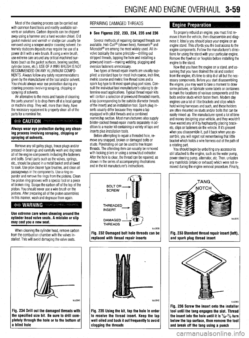
# See Figures 232, 233, 234, 235 and 236
Several methods of repairing damaged threads are
available Heli-Coil@ (shown here), Keenserts@ and
Microdop are among the most widely used. All in-
volve basically the same principle-drilling out
stripped threads, tapping the hole and installing a
prewound insert-making welding, plugging and
oversize fasteners unnecessary.
Two types of thread repair inserts are usually sup-
plied: a standard type for most inch coarse, rnch fine,
metric course and metrrc fine thread sizes and a
spark lug type to fit most spark plug port sizes. Con-
sult the individual tool manufacturers catalog to de-
termine exact applications. Typical thread repair kits
will contain a selection of prewound threaded inserts,
a tap (corresponding to the outside diameter threads
of the insert) and an installation tool. Spark plug in-
serts usually differ because they require a tap
equipped wrth pilot threads and a combined
reamer/tap section. Most manufacturers also supply
blister-packed thread repair Inserts separately in ad-
dition to a master kit containing a variety of taps and
inserts plus installation tools
Before attempting to repair a threaded hole, re-
move any snapped, broken or damaged bolts or
studs. Penetrating oil can be used to free frozen
threads. The offending item can usually be removed
with locking pliers or using a screw/stud extractor.
After the hole is clear, the thread can be reparred, as
shown in the series of accompanying illustrations
and in the krt manufacturers instructions.
THREADED
lCCS3039
replaced with thread repair inserts
:ig. 235 Using the kit, tap the hole in order
o receive the thread insert. Keep the tap
veil oiled and back it out frequently to avoid
:logging the threads
To properly rebuild an engine, you must first re-
move it from the vehicle, then disassemble and diag-
nose it. Ideally you should place your engine on an
engine stand. This affords you the best access to the
engine components. Follow the manufacturers direc-
tions for using the stand with your particular engine.
Remove the flywheel or flexplate before installing the
engine to the stand.
Now that you have the engine on a stand, and as-
suming that you have drained the oil and coolant
from the engine, it’s time to strip it of all but the nec-
essary components. Before you start disassembling
the engine, you may want to take a moment to draw
some pictures, or fabricate some labels or containers
to mark the locations of various components and the
bolts and/or studs which fasten them. Modern day
engines use a lot of little brackets and clips which
hold wiring harnesses and such, and these holders
are often mounted on studs and/or bolts that can be
easily mixed up. The manufacturer spent a lot of time
and money designing your vehicle, and they wouldn’t
have wasted any of it by haphazardly placing brack-
ets, clips or fasteners on the vehicle. If it’s present
when you disassemble it, put it back when you as-
semble, you will regret not remembering that little
bracket which holds a wire harness out of the path of
a rotating part.
You should begin by unbolting any accessories
still attached to the engine, such as the water pump,
power steering pump, alternator, etc. Then, unfasten
any manifolds (intake or exhaust) which were not re-
moved during the engine removal procedure. Finally,
Fig. 233 Standard thread repair insert (left),
and spark plug thread insert
im3043 Fig. 236 Screw the insert onto the installer
1001 until the tang engages the slot. Thread
‘he insert into the hole until it is l/4-l/~ turn
lelow the top surface, then remove the tool
and break off the tano usina a uunch
Page 121 of 408
3-60 ENGINE/
-w
remove any covers remaining on the engine such as
on today’s automobiles: the Overhead Valve (OHV)
and the Overhead Camshaft (OHC). The latter can
also be broken down into two subgroups: the Single the rocker arm, front or timing cover and oil pan.
Overhead Camshaft (SOHC) and the Dual Overhead
Camshaft (DOHC). Generally, if there is only a single
camshaft on a head. it is iust referred to as an OHC Some front covers may require the vibration damper
and/or crank pulley to be removed beforehand. The
idea is to reduce the engine to the bare necessities
(cylinder head(s), valve train, engine block, crank-
shaft, pistons and connecting rods), plus any other
‘in block’ components such as oil pumps, balance
shafts and auxiliary shafts.
Finally, remove the cylinder head(s) from the en-
gine block and carefully place on a bench. Disassem-
bly instructions for each component follow later in
this section.
There are two basic types of cylinder heads used
Most cylinder heads these days are made of an
aluminum alloy due to its light weight, durability and
L--L I _--- 1^- _..^ I:,:^^ I I ^...^. .^_ ^^^I :_-_ ..^^ ,L- same environment. The same goes for any other unchanged. One aspect to pay attention to is careful
component on the cylinder head. Think of it as an in- labeling of the parts on the dual camshaft cylinder
“’ surance policy against future problems related to that head. There will be an intake camshaft and followers
component. as well as an exhaust camshaft and followers and
Unfortunately, the only way to find out which com- they must be labeled as such. In some cases, the
ponents need replacing, is to disassemble and care- components are identical and could easily be in-
fully check each piece. After the cylinder head(s) are stalled incorrectly. DO NOT MIX THEM UP! Deter-
disassembled, thoroughly clean all of the compo- mining which is which is very simple; the intake
nents. camshaft and components are on the same side of
DISASSEMBLY the head as was the intake manifold. Conversely, the
exhaust camshaft and components are on the same
side of the head as was the exhaust manifold.
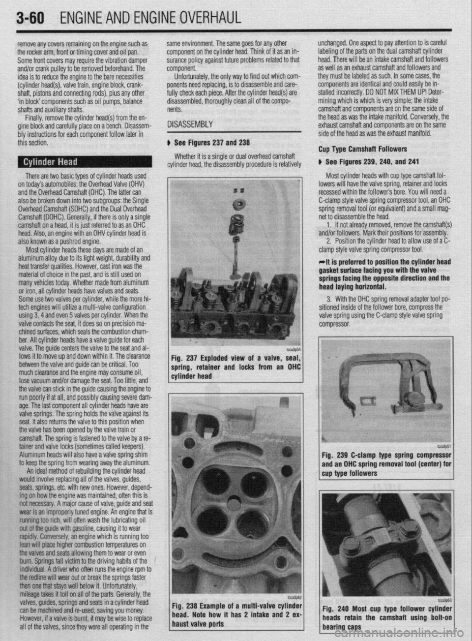
ti See Figures 237 and 238
Whether it is a single or dual overhead camshaft Cup Type Camshaft Followers
cylinder head, the disassembly procedure is relatively 6 See Figures 239, 240, and 241
t “” ““’ 1 Most cylinder heads with cup type camshaft fol-
1 1 head. Also, an engine with an OHV cylinder head is j:, ’
I also known as a pushrod engine. : .; :-,
_I lowers will have the valve spring, retainer and locks
recessed within the followers bore. You will need a
C-clamp style valve spring compressor tool, an OHC
spring removal tool (or equivalent) and a small mag-
net to disassemble the head.
1. If not already removed, remove the camshaft(s)
and/or followers, Mark their positions for assembly.
2. Position the cylinder head to allow use of a C-
clamp style valve spring compressor tool.
IIRN il~llSlt?l ~Lldll~l~S. IlUWttVtJ, MS1 11011 W8S lilt: material of choice in the past, and is still used on
many vehicles today. Whether made from aluminum
or iron, all cylinder heads have valves and seats.
Some use fwo valves per cylinder, while the more hi-
tech engines will utilize a multi-valve configuration
using 3‘4 and even 5 valves per cylinder. When the
valve contacts the seat, it does so on precision ma-
chined surfaces, which seals the combustion cham-
ber, All cylinder heads have a valve guide for each
valve. The auide centers the valve to the seat and al-
lows it to move up and down within it. The clearance
between the valve and guide can be critical. Too
much clearance and the engine may consume oil,
lose vacuum and/or damaae the seat. Too little. and
the valve can stick in the guide causing the engine to
run poorly if at all, and possibly causing severe dam-
age. The last component all cylinder heads have are
valve springs. The spring holds the valve against its
seat. It also returns the valve to this position when
the valve has been opened by the valve train or
camshaft. The spring is fastened to the valve by a re-
tainer and valve locks (sometimes called keepers).
Aluminum heads will also have a valve spring shim
to keep the spring from wearing away the aluminum. Fig, 237 Exploded view of a valve, seal,
1 cylinder head ----r- 1 spring, retamer and locks from an OHC
An ideal method of rebuilding the cylinder head
would involve replacing all of the valves, guides,
seats, springs, etc. with new ones. However, depend-
ing on how the engine was maintained, often this is
not necessary. A major cause of valve, guide and seat
wear is an improperly tuned engine. An engine that is
~~f~t~~ rich, will often wash the lubricating oil
out ofthe guide with gasoline, causing it to wear
~~fdfy. lonely, an engine which is running too
lean wifl pface higher combustion temperatures on
Me valves and seats allowing them to wear or even
bum. Springs fall victim to the driving habits of the
f~~iduaf. A driver who often runs the engine rpm to
tfre redfine will wear out or break the springs faster
then one tfrat stays well below it. Unfortunately,
mileage takes it tot1 on all of the parts. Generally, the
valves, guides, springs and seats in a cylinder head
can be machined and re-used, saving you money.
.However, if a valve is burnt, it may be wise to replace
all of the valves, since they were all operating in the oi a multi-valve cylinder
t has 2 intake
and 2 ex-
At is preferred to position the cylinder head lasket’surtace facing you with tee valve
springs facing the opposite direction and the
lead laying horizontal.
3. With the OHC spring removal adapter tool po-
,itioned inside of the follower bore, compress the
alve spring using the C-clamp style valve spring
:ompressor.
tcca3p51 fig. 239 C-clamp type spring compressor
and an OHC spring removal tool (center) for
cup type followers
Fig. 240 Most cup type follower cylinder
/ heads retain the camshaft using bolt-on
bearing caps
Page 123 of 408
.
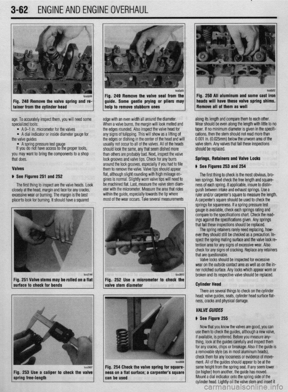
3-62 ENGINEANDENGINEOVERHAUL
lge. To accurately inspect them, you will need some
,pecialized tools:
l A O-l in. micrometer for the valves l A dial indicator or inside diameter gauge for
he valve guides
l A spring ressure test gau e
If you do no P Yl have access to t e proper tools,
‘ou may want to bring the components to a shop
hat does.
lalves
1 See Figures 251 and 252
The first thing to inspect are the valve heads. Look
E :losely at the head, margin and face for any cracks,
rxcessive wear or burning. The margin is the best
)lace?o look for burning. It should have a squared E
c
edge with an even width all around the diameter.
When a valve burns, the margin will look melted and
the edges rounded. Also inspect the valve head for
any signs of tulipping. This will show as a lifting of
the edges or dishing in the center of the head and will
usually not occur to all of the valves. All of the heads
should look the same, any that seem dished more
than others are probably bad. Next, inspect the valve
lock grooves and valve tips. Check for any burrs
around the lock grooves, especially if you had to file
them to remove the valve. Valve tips should appear
flat, although slight rounding with high mileage en-
gines is normal. Slightly worn valve tips will need to
be machined flat. last, measure the valve stem diam-
eter with the micrometer. Measure the area that rides
within the guide, especially towards the tip where
most of the wear occurs. Take several measurements along its length and compare them to each other.
Wear should be even along the length with little to no
taper. If no minimum diameter is given in the specifi-
cations, then the stem should not read more than
0.001 in. (0.025mm) below the unworn area of the
valve stem. Any valves that fail these inspections
should be replaced.
Springs, Retainers and Valve Locks
$ See Figures 253 and 254
The first thing to check is the most obvious, bro-
ken springs. Next check the free length and square-
ness of each spring. If applicable, insure to distin-
guish between intake and exhaust springs. Use a
ruler and/or carpenter’s square to measure the length.
A carpenter’s square should be used to check the
lCZS3144
I I hrnknn itc Fig. 251 Valve stems may be rolled on a flat Fio. 252 Use a micrometer
suhace to check for bends
valve stem diameter r to check the
I
There are seve Cylinder Head
ral things to check on the cylinder
head: valve guides, seats, cylinder head surface flat-
ness, cracks and physical damage.
VA1 YE GUIDES
N See Figure 255
Now that you know the valves are good, you can
254 Check the valve spring fo
s on a flat surface; a carpenter use them to check the guides, although a new valve,
if available, is preferred. Before you measure any-
thing, look at the guides carefully and inspect them
for any cracks, chips or breakage. Also if the guide is
a removable style (as in most aluminum heads),
check them for any looseness or evidence of move-
ment. All of the guides should appear to be at the
same height from the spring seat. If any seem lower
(or higher) from another, the guide has moved.
Mount a dial indicator onto the sorina side of the
cylinder head. Lightly oil the valve stem and insert it
Page 124 of 408
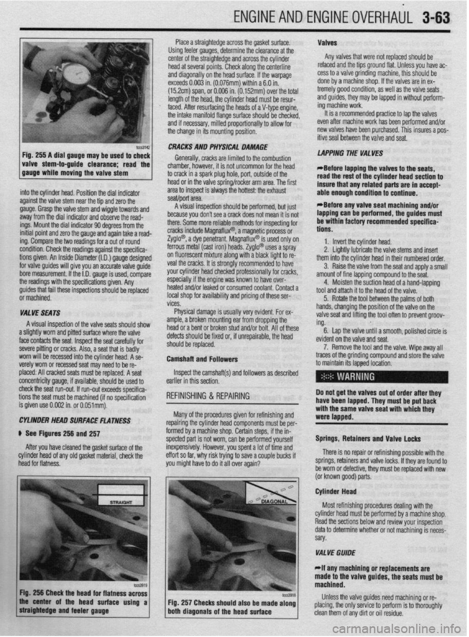
ENGINEANDENGINEOVERHAUL 3-63
Place a straightedge across the gasket surface. Valves
Using feeler gauges, determine the clearance at the
center of the straightedge and across the cylinder Any valves that were not replaced should be
head at several points. Check along the centerline refaced and the tips ground flat. Unless you have ac-
and diagonally on the head surface. If the warpage cess to a valve grinding machine, this should be
exceeds 0.003 in. (0.076mm) within a 6.0 in. done by a machine shop. If the valves are in ex-
(152cm) span, or 0.006 in. (0.152mm) over the total tremely good condition, as well as the valve seats
length of the head, the cylinder head must be resur- and guides, they may be lapped in without petform-
,
I mg macnme worK.
4
It is a recnmmended practice to lap the valves faced. After resurfacing the heads of a V-type engine
the intake manifold flange surface should be checker,
and if necessary, milled proportionally to allow for
the change in its mounting position. _ - _ _ _ .- - - _
even after machine work has been p&formed and/or
new valves have been purchased. This insures a pos-
itive seal between the valve and seat.
-guide clearance; the 1
read
. .
into the cylinder head. Position the dial indicator
against the valve stem near the tie and zero the
gauge. Grasp the valve stem and’wiggle towards and
away from the dial indicator and observe the read-
ings. Mount the dial indicator 90 degrees from the
initial point and zero the gauge and again take a read-
ing. Compare the two readings for a out of round
condition. Check the readings against the specifica-
tions given. An Inside Diameter (I.D.) gauge designed
for valve guides will give you an accurate valve guide
bore measurement. If the I.D. gauge is used, compare
the readings with the specifications given. Any CRACKS AND PHYSICAL DAMAGE
Generally, cracks are limited to the combustion
chamber, hbwever, it is not uncommon for the head
to crack in a spark plug hole, port, outside of the
head or in the valve spring/rocker arm area. The first
area to inspect is always the hottest: the exhaust
.I *
seawpon area.
8 I .,“““I llly”Lv”l~ .ml”“l” - plr”llll”“, ““I ,“a’
because you don’t see a crack does not mean it is not
there. Some more reliable methods for inspecting for
cracks include Magnaflux? a magn$i,c process or
Zyglo? a dye penetrant. Ma{ -’
InatluxW IS used only on
ferrous metal (cast iron) heat Is. Zyglo@ uses a spray
on fluorescent mixture along with a black light to re-
veal the cracks. It is strongly recommended to have
your cylinder head checked professionally for cracks,
especially if the engine was known to have over-
I .* I,. ..^.. LAPPING THE VALVES
*Before iaoaino the valves to the seats,
read the rest of the cylinder head section to
insure that any related parts are in accept-
able enough condition to continue.
*Before anv valve seat machining and/or
lapping can be performed, the guides must
be within factory recommended specifica-
tions.
1. Invert the cylinder head.
2. Linhtlv Iuhrir;rB the valve stems and insert
-. _ ~ . . . . . .--.._-._
them into the cylinder head in their numbered order.
3. Raise the valve from the seat and apply a small
amount of fine lanninn compound to the seat.
4.
i guides that fail these inspections should be replaced nearea analor ieaKea or consumea coolant. Contact a Moisten the suction head of a hand-lapping
tool and attach it to the head of the valve.
i or machined. local shop for availability and pricing of these ser-
5. Rotate the tool between the palms of both
I vices.
I
VALVE SEATS Physical damage is usually very evident. For ex- hands, changing the position of the valve on the
valve seat and lifting the tool often to prevent groov-
A visual inspection of the valve seats should show
amnb P hrnbn mntlntinn ear from dropping the I and/or bolt. All of these ing.
.a,... . 6. Lap the valve until a smooth, polished circle is
a slightly worn and pitted surface where the valve
face contacts the seat. Inspect the seat carefully for
severe pitting or cracks. Also, a seat that is badly
worn will be recessed into the cylinder head. A se-
verely worn or recessed seat may need to be re- uetecIs SIIOUIO oe nxea or, IT unrepairaole, me neaa
should be replaced.
Camshaft and Followers evid
7
traces of the grinding corn
to maintain its lapped loca lent on the valve and seat.
‘. Remove the tool and the valve. Wipe away all
pound and store the valve
placed: All cracked seats must be replaced. A seat
concentricity gauge, if available, should be used to
check the seat run-out. If run-out exceeds specifica-
tions the seat must be machined (if no soecification
is given use 0.002 in. or O.O51mt$. Inspect the camshaft(s) and followers as described
earlier in this section.
REFINISHING & REPAIRING Do not get the valves out of order after they
have been lapped. They must be put back
: ..^^ I... --I:^:-L!-- --A
Many of the procedures gIveI
WI WIIIIISIIIIIIJ ~IIU repairing the cylinder head components must be per-
formed by a machine shop. Certain steps, if the in-
spected part is not worn, can be performed yourself
inexpensively. However, you spent a lot of time and
effort so far, why risk trying to save a couple bucks if
you might have to do it all over again?
I- with the same valve seat with which they
were lapped.
Springs, Retainers and Valve locks
There is no repair or refinishing possible with the
springs, retainers and valve locks. If they are found to
be worn or defective, they must be replaced with new
lor known nnod narts CYLtNDEt? HEAD SURFACE FLATNESS
) See Figures 256 and 257
After you have cleaned the gasket surface of the
cylinder head of any old gasket material, check the
head for flatness.
\- - a---r r- .-.
Cylinder Head
Most refinishing procedures dealing with the
VALVE GWDE
elf any machining or replacements are
e valve guides, the seats must be
Fig. 257 Checks should also be made along Unless the valve guides need machining or re-
placing, the only service to perform is to thoroughly‘
clean them of any dirt or oil residue.
Page 125 of 408
.
3-64 ENGINEANDENGINEOVERHAUL
There are only two types of valve guides used on
automobile engines: the replaceable-type (all alu-
minum heads) and the cast-in integral-type (most
cast iron heads). There are four recommended meth-
ods for repairing worn guides.
. Knurling
l Inserts l Reaming oversize l Replacing
Knurling is a process in which metal is displaced
and raised, thereby reducing clearance, giving a true
center, and providing oil control. It is the least ex-
pensive way of repairing the valve guides. However,
it is not necessarily the best, and in some cases, a
knurled valve guide will not stand up for more than
a short time. It requires a special knurlizer and pre-
cision reaming tools to obtain proper clearances. It
would not be cost effective to purchase these tools,
unless you plan on rebuilding several of the same
cylinder head.
Installing a guide insert involves machining the
guide to accept a bronze insert. One style is the coil-
type which is installed into a threaded guide. Another
is the thin-walled insert where the guide is reamed machined.
If the seats are in good condition, the valves can
be lapped to the seats, and the cylinder head assem-
bled. See the valves section for instructions on lap-
ping.
If the valve seats are worn, cracked or damaged,
they must be serviced by a machine shop. The valve
seat must be perfectly centered to the valve guide,
which requires very accurate machining.
CYLINDER HEAD SURFACE
If the cylinder head is warped, it must be ma-
chined flat. If the warpage is extremely severe, the
head may need to be replaced. In some instances, it
may be possible to straighten a warped head enough
to allow machining. In either case, contact a profes-
sional machine sh& for service. Cup Type Camshafl Followers
To install the springs, retainers and valve locks on
heads which have these components recessed into
the camshaft followers bore, you will need a small
I” .1.1.“1.“”
., ,, just after compressing the spring but before the *Any OHC cylinder head that shows exces-
sive warpage should have the camshaft bear-
ing journals align bored after the cylinder
head has been resurfaced. screwdriver-type tool, some clean white grease and a
lot of patience. You will also need the C-clamp style
spring compressor and the OHC tool used to disas-
semble the head.
1. Lightly lubricate the valve stems and insert all
of the valves into the cylinder head. If possible, main-
tain their original locations.
2. If equipped, install any valve spring shims
which were removed.
3. If equipped, install the new valve seals, keep-
ing the following in mind:
l If the valve seal presses over the guide,
lightly lubricate the outer guide surfaces.
l If the seal is an 0-rina tvoe. it rc rn+#fld
valve locks.
4. Place thevalve spring and retainer over the
stem.
5. Position the spring compressor and the OHC
tool, then compress the spring.
6. Using a small screwdriver as a spatula, fill
the valve stem side of the lock with white grease. Use
the excess grease on the screwdriver to fasten the
lock to the driver.
7. Carefully install the valve lock, which is stuck
to the end of the screwdriver, to the valve stem then
press on it with the screwdriver until the grease
squeezes out. The valve lock should now be stuck to
the stem.
8. Repeat Steps 6 and 7 for the remaining valve
lock. :
oversize to accept a split-sleeve insert. After the in-
sert is installed, a special tool is then run through the
guide to expand the insert, locking it to the guide.
The insert is then reamed to the standard size for
proper valve clearance.
Reamina for oversize valves restores normal clear- Failure to align bore the camshaft bearing
journals could result in severe engine dam-
age including but not limited to: valve and
oiston damage. connectinu rod damaoe,
iamshaft and/or crankshaft breakage,
antes and provides a true valve seat. Most cast-in
i tvpe guides can be reamed to accept an valve with an CRACKS AND PHYSICAL DAMAGE
oversize stem. The cost factor for this can become
quite high as you will need to purchase the reamer
and new, oversize stem valves for all guides which
were reamed. Oversizes are generally 0.003 to 0.030
in. (0.076 to 0.762mm), with 0.015 in. (0.381mm)
being the most common.
To replace cast-in type valve guides, they must be
drilled out, then reamed to accept replacement
guides, This must be done on a fixture which will al-
low centering and leveling off of the original valve
seat or quide, otherwise a serious guide-to-seat mis-
alignment may occur making it impossible to prop-
erly machine the seat.
Replaceable-type guides are pressed into the
cylinder head. A hammer and a stepped drift or
punch may be used to install and remove the guides.
Before removing the guides, measure the protrusion
on the spring side of the head and record it for instal-
tation. Use the stepped drift to hammer out the old
guide from the combustion chamber side of the head.
when in~llfng, determine whether or not the guide
also seals a water jacket in the head, and if it does,
use the ~o~ended sealing agent. If there is no
water jacket grease the valve guide and its bore. Use
the stepped drift, and hammer the new guide into the
cylinder head from the spring side of the cylinder
head. A stack af washers the same thickness as the
measured Eaton may help the installation Certain cracks can be repaired in both cast iron
and aluminum heads. For cast iron, a tapered
threaded insert is installed along the length of the
crack. Aluminum can also use the tapered inserts,
however welding is the preferred method. Some
physical damage can be repaired through brazing or
welding. Contact a machine shop to get expert advict
for your particular dilemma.
ASSEMBLY
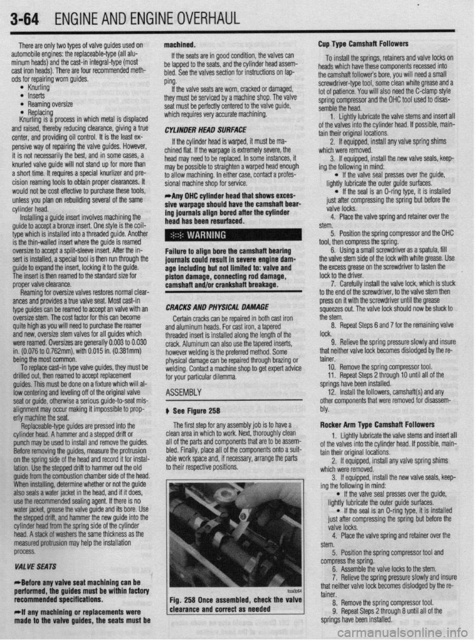
+ See Figure 258
The first step for any assembly job is to have a
clean area in which to work. Next, thoroughly clean
all of the parts and components that are to be assem-
bled. Finally, place all of the components onto a suit-
able work space and, if necessary, arrange the parts
to their respective positions.
process.
VALVE SEATS
*Before any valve seat maChining can be
aerformed. the guides must be within factory
recommended specifications.
-
1 Fig. 258 Once assembled, check the valve
;
rlf any machtning or replacements were 1 clearance and correct as needed
I
made to the valve guides, the seats must be 9. Relieve the spring pressure slowly and insure
that neither valve lock becomes dislodged by the re-
tainer.
10. Remove the spring compressor tool.
11. Repeat Steps 2 through 10 until all of the
springs have been installed.
12. Install the followers, camshaft(s) and any
other components that were removed for disassem-
bly.
Rocker Arm Type Camshaft Followers
1. Lightly lubricate the valve stems and insert all
of the valves into the cylinder head. If possible, main-
tain their original locations.
2. If equipped, install any valve spring shims
which were removed.
3. If equipped, install the new valve seals, keep-
ing the following in mind:
l If the valve seal presses over the guide,
lightly lubricate the outer guide surfaces.
l If the seal is an O-ring type, it is installed
just after compressing the spring but before the
valve locks.
4. Place the valve spring and retainer over the
stem.
5. Position the spring compressor tool and
compress the spring.
6. Assemble the valve locks to the stem.
7. Relieve the spring pressure slowly and insure
that neither valve lock becomes dislodged by the re-
tainer.
8. Remove the spring compressor tool.
9. Repeat Steps 2 through 8 until all of the
springs have been installed.
Page 129 of 408
.
3-68 ENGINEANDENGINEOVERHAUL
crankshaft end-play 8. Install the rear main seal.
the inner portion of the lower land. If the lower
9. After the bearings have been fitted, apply a
lands have high steps, the piston should be re-
light coat of engine oil to the journals and bearings.
placed.
Install the rear main bearing cap. Install all bearing
2. Unless new pistons are installed, be sure to
caps except the thiust bearing cap. Be sure that main
I
install the pistons in the cylinders from which they
bearing caps are installed in original locations.
were removed. The numbers on the connecting rod
Tighten the bearing cap bolts to specifications.
and bearing cap must be on the same side when in-
10. Install the thrust bearing cap with bolts fin-
stalled in the cylinder bore. If a connecting rod is
ger-tight.
ever transposed from one engine or cylinder to an-
11. Pry the crankshaft forward against the thrust
other, new bearings should be fitted and the connect-
surface of upper half of bearing.
ing rod should be numbered to correspond with the *
12. Hold the crankshaft forward and pry the thrust
new cylinder number. The notch on the piston head
bearing cap to the rear. This aligns the thrust sur-
goes toward the front of the engine.
faces of both halves of the bearing.
3. Install all of the rod bearing inserts into the
13. Retain the forward pressure on the crankshaft.
rods and caps.
Tighten the cap bolts to specifications.
4. Install the rings to the pistons. Install the oil
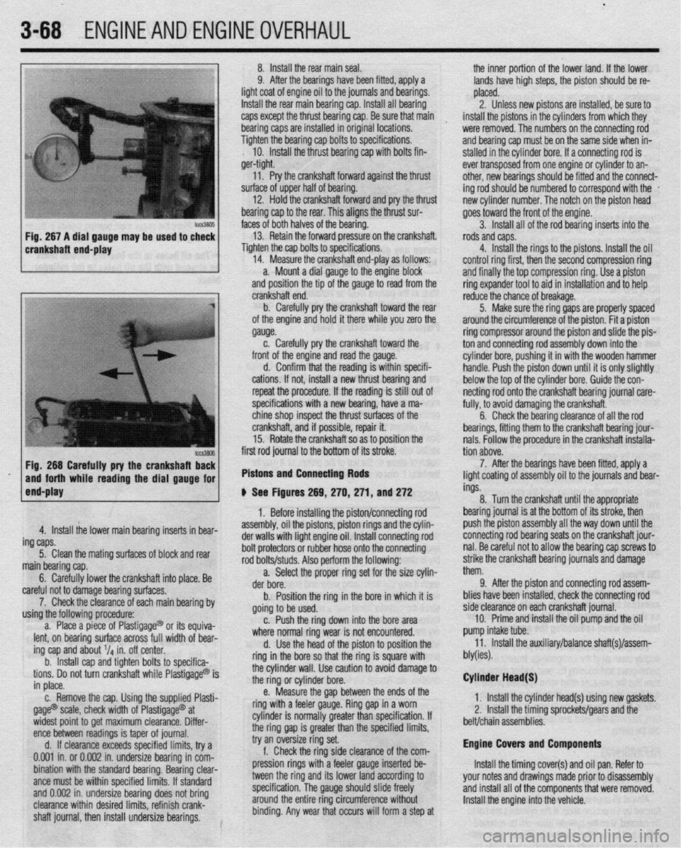
14. Measure the crankshaft end-play as follows:
control ring first, then the second compression ring
a. Mount a dial gauge to the engine block
and finally the top compression ring. Use a piston
and position the tip of the gauge to read from the
ring expander tool to aid in installation and to help
Fig. 266 Carefully pry the crankshafl Ez
and forth while reading the dial gauge for
end-play first rod journal to the bottom of its stroke.
Pistons and Connecting Rods
4. Install the lower main bearing inserts in bear-
ing caps.
5. Clean the mating surfaces of block and rear
main bearing cap.
6. Carefully lower the crankshaft into place. Be
careful not to damage bearing surfaces.
7. Check the clearance of each main bearing by
using the following procedure:
a. Place a piece of Plastigage@ or its equiva-
lent, on bearing surface across full width of bear-
ing cap and about V4 in. off center.
b. Install cap and tighten bolts to specifica-
tions. Do not turn crankshaft while Plastigage@ is
in place.
c. Remove the cap. Using the supplied Plasti-
gage@ scale, check width of Plastigage@ at
widest point to get maximum clearance. Differ-
ence between readings is taper of journal.
d. If clearance exceeds specified limits, try a
0.001 in. or 0.002 in. undersize bearing in com-
bination with the standard bearing. Bearing clear-
ante must be within specified limits. If standard
and 0.002 in. undersize bearing does not bring
clearance within desired limits, refinish crank-
shaft journal, then install undersize bearings. crankshaft end.
b. Carefully pry the crankshaft toward the rear
of the engine and hold it there while you zero the
gauge.
c. Carefully pry the crankshaft toward the
front of the engine and read the gauge.
d. Confirm that the reading is within specifi-
cations. If not, install a new thrust bearing and
repeat the procedure. If the reading is still out of
specifications with a new bearing, have a ma-
chine shop inspect the thrust surfaces of the
crankshaft, and if possible, repair it.
15. Rotate the crankshaft so as to position the
# See Figures 269, 270,271, and 272
1. Before installing the piston/connecting rod
assembly, oil the pistons, piston rings and the cylin-
der walls with light engine oil. Install connecting rod
bolt protectors or rubber hose onto the connecting
rod bolts/studs. Also perform the following:
a. Select the proper ring set for the size cylin-
der bore.
b. Position the ring in the bore in which it is
going to be used.
c. Push the ring down into the bore area
where normal ring wear is not encountered.
d. Use the head of the piston to position the
ring in the bore so that the ring is square with
the cylinder wall. Use caution to avoid damage to
the ring or cylinder bore.
e. Measure the gap between the ends of the
ring with a feeler gauge. Ring gap in a worn
cylinder is normally greater than specification. If
the ring gap is greater than the specified limits,
try an oversize ring set.
f. Check the ring side clearance of the com-
pression rings with a feeler gauge inserted be-
tween the ring and its lower land according to
specification. The gauge should slide freely
around the entire ring circumference without
binding. Any wear that occurs will form a step at reduce the chance of breakage.
5. Make sure the ring gaps are properly spaced
around the circumference of the piston. Fit a piston
ring compressor around the piston and slide the pis-
ton and connecting rod assembly down into the
cylinder bore, pushing it in with the wooden hammer
handle. Push the piston down until it is only slightly
below the top of the cylinder bore. Guide the con-
netting rod onto the crankshaft bearing journal care-
fully, to avoid damaging the crankshaft.
6. Check the bearing clearance of all the rod
bearings, fitting them to the crankshaft bearing jour-
nals. Follow the procedure in the crankshaft installa-
tion above.
7. After the bearings have been fitted, apply a
light coating of assembly oil to the journals and bear-
ings.
8. Turn the crankshaft until the appropriate
bearing journal is at the bottom of its stroke, then
push the piston assembly all the way down until the
connecting rod bearing seats on the crankshaft jour-
nal. Be careful not to allow the bearing cap screws to
strike the crankshaft bearing journals and damage
them.
9. After the piston and connecting rod assem-
blies have been installed, check the connecting rod
side clearance on each crankshaft journal.
10. Prime and install the oil pump and the oil
pump intake tube.
11. Install the auxiliary/balance shaft(s)/assem-
bly(ies).
Cylinder Head(S)
1. Install the cylinder head(s) using new gaskets.
2, Install the timing sprockets/gears and the
belt/chain assemblies.
Engine Covers and Components
Install the timing cover(s) and oil pan. Refer to
your notes and drawings made prior to disassembly
and install all of the components that were removed.
Install the engine into the vehicle.
Page 150 of 408
.
DRIVEABILITYAND EMISSIONS CONTROLS 4-7
6. Clean the mating surfaces on the valve and
the engine. Make sure to remove all gasket material.
7. Inspect the valve for a sticking plunger,
caused by excess carbon deposits. If such a condi-
tion exists, clean with appropriate solvent so valve
seats correctly.
To install:
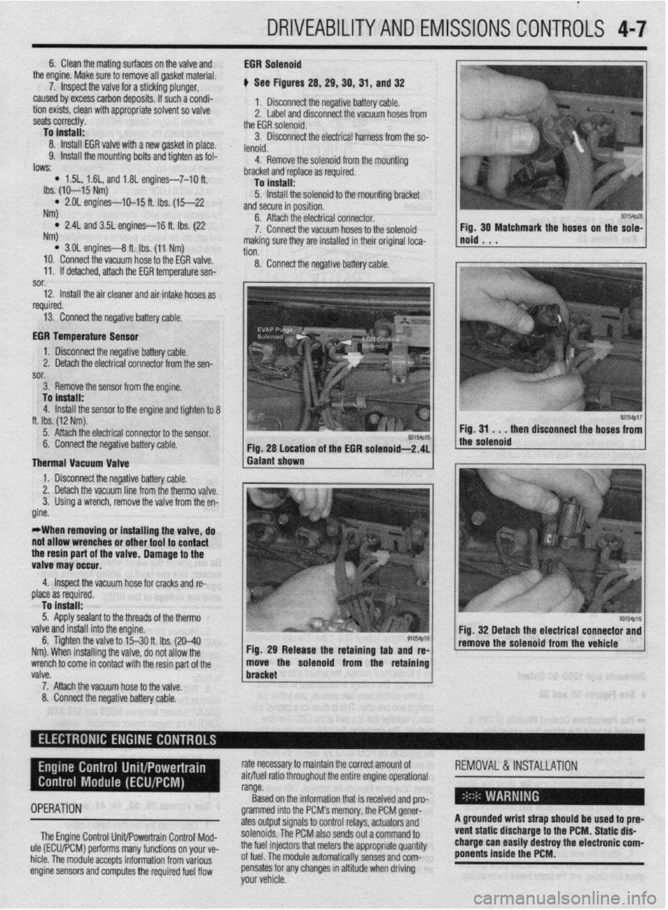
8. Install EGR valve with a new gasket in place.
9. Install the mounting bolts and tighten as fol- EGR Solenoid
e See Figures 28, 29, 39, 31, and 32
1. Disconnect the negative battery cable.
2. Label and disconnect the vacuum hoses from
the EGR solenoid.
3. Disconnect the electrical harness from the so-
lenoid.
4. Remove the solenoid from the mountino
lows: * 1.5L, 1.6L, and 1.81 engines-7-10 ft.
Ibs. (IO-15 Nm)
l 2.OL engines-IO-15 ft. Ibs. (15-22
NW
l 2.4L and 3.5L engines-16 ft. Ibs. (22
NW
l 3.01 engines-8 ft. Ibs. (11 Nm)
10. Connect the vacuum hose to the EGR valve.
11. If detached, attach the EGR temperature sen- -
bracket and replace as required.
To install:
5. Install the solenoid to the mounting bracket
and secure in position.
6. Attach the electrical connector.
7. Connect the vacuum hoses to the solenoid
making sure they are installed in their original loca-
tion.
8. Connect the negative battery cable.
sor.
12. Install the air cleaner and air intake hoses as
I
required.
13. Connect the negative battery cable.
EGR Temperature Sensor
1. Disconnect the negative battery cable.
2. Detach the electrical connector from the sen-
sor.
3. Remove the sensor from the engine.
To install:
4. Install the sensor to the engine and tighten to 8
ft. Ibs. (12 Nm).
5. Attach the electrical connector to the sensor.
6. Connect the negative battery cable.
Thermal Vacuum Valve
1. Disconnect the negative battery cable. Fig. 28 Location of the EGR solenoid-2.41
Galant shown
valve.
7. Attach the vacuum hose to the valve 1 bracket 6. Tighten the valve to l‘j30 ft. Ibs. (20-40
91054p19
Nm). When installing the valve, do not allow the Fig. 29 Release the retaining tab and re-
wrench to come in contact with the resin part of the move the solenoid from the retaining Fig, 30 Matchmark the hoses on the sole-
noid . . .
8. Connect the negative battery cable.
Page 193 of 408
install the line to the fuel rail. Tighten the mounting
bolts,
19. Attach the PCV hose and the breather hose if
thev were disconnected.
20. Connect the negative battery cable. Pressur-
ize the fuel system and inspect all connections for
I
leaks.
1.6L and 2.01 DOHC Engines
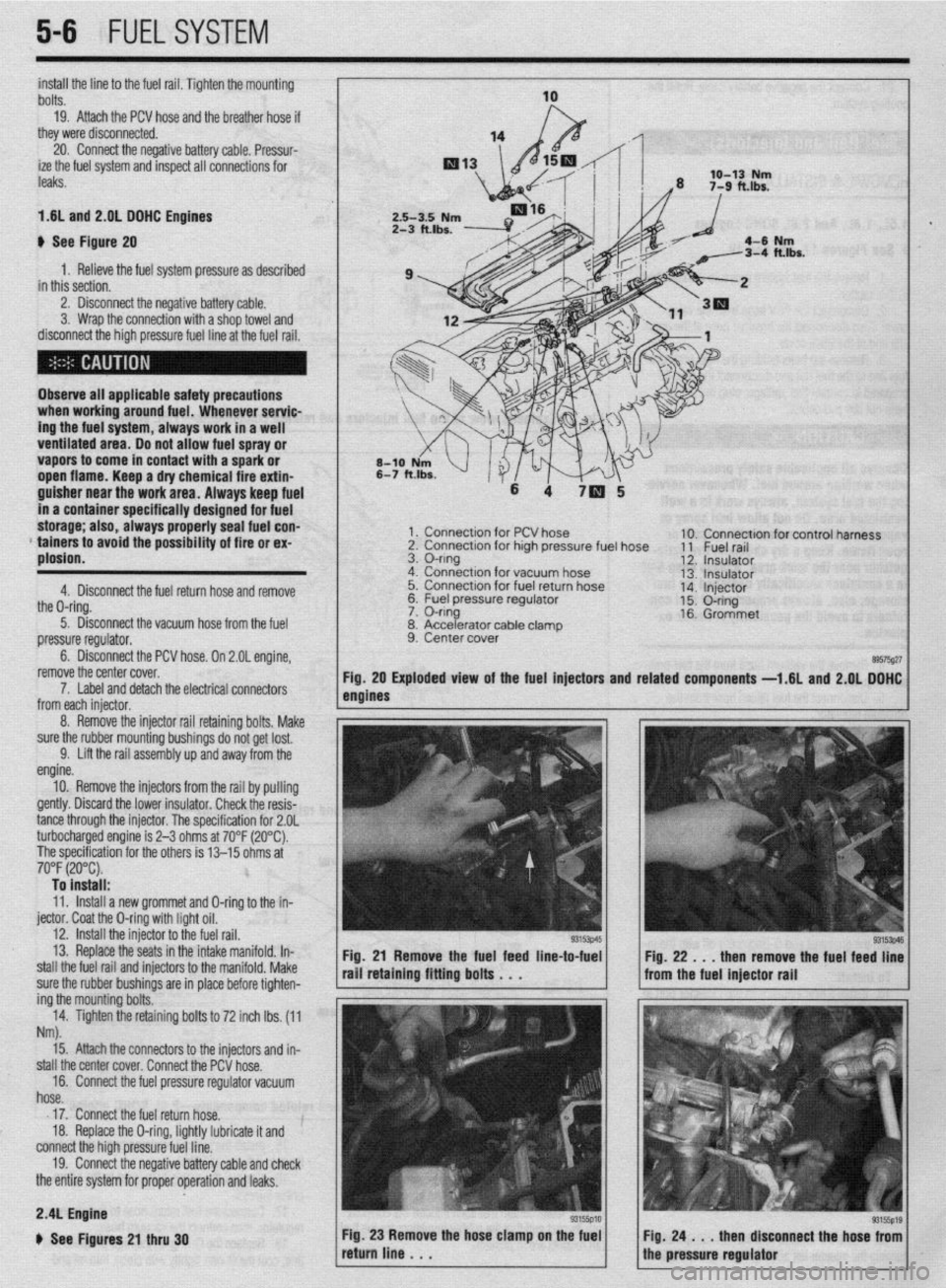
b See Figure 20
1. Relieve the fuel system pressure as described
in this section.
2. Disconnect the negative battery cable.
3. Wrap the connection with a shop towel and
disconnect the high pressure fuel line at the fuel rail.
Observe all applicable safety precautions
when working around fuel. Whenever servic-
ing the fuel system, always work in a well
ventilated area. Do not allow fuel spray or
vapors to come in contact with a spark or
open flame. Keep a dry chemical fire extin-
guisher near the work area. Always keep fuel
in a container specifically designed for fuel
storage; also, always properly seal fuel con-
* tainers to avoid the possibility of fire or ex-
plosion.
4. Disconnect the fuel return hose and remove
the O-ring.
5. Disconnect the vacuum hose from the fuel
pressure regulator.
6. Disconnect the PCV hose. On 2.OL engine,
remove the center cover.
1 x Connection for PCV hose
2. Connection for high pressure fuel hose
3. O-ring
4. Connection for vacuum hose
5. Connection for fuel return hose
&2 I=, 1c.1 nrncc*.ra regu,ator
lble clamD
7. Label and detach the electrical connectors
from each iniector.
8. Accelerator ca
9. Center cover . 10. Connection for control harness
11 Fuel rail
12. Insulator
13. Insulator
14. Injector
15. O-ring
16. Grommet
89575g27 Exploded view of the fuel injectors and related
components -1.6L and 2.QL DOHC
5-6 FUELSYSTEM
8. Remove the injector rail retaining bolts, Make
sure the rubber mounting bushings do not get lost.
9. Lift the rail assembly up and away from the
engine.
10. Remove the injectors from the rail by pulling
gently. Discard the lower insulator. Check the resis-
tance through the injector. The specification for 2.OL
turbocharged engine is 2-3 ohms at 70°F (20°C).
The specification for the others is 13-15 ohms at
70°F (20°C). To install:
11. Install a new grommet and O-ring to the in-
jector. Coat the O-ring with light oil.
12. install the injector to the fuel rail.
13. Replace the seats in the intake manifold. In-
stall the fuel rail and injectors to the manifold. Make
sure the rubber bushings are in place before tighten-
ing the mounting bolts.
14. Tighten the retaining bolts to 72 inch lbs. (11
Nm).
Fig. 21 Remove the fuel feed line-to-fuel
rail retaining fitting bolts . . .
15. Attach the connectors to the injectors and in-
stall the center cover. Connect the PCV hose.
16. Connect the fuel pressure regulator vacuum
hose.
17. Connect the fuel return hose.
18. Replace the O-ring, lightly lubricate it and
connect the high pressure fuel line.
19. Connect the negative battery cable and check
the entire system for proper operation and leaks. Fig. 22 . . . then remove the fuel feed line
from the fuel injector rail
2.4L Engine
b See Figures 21 thru 30