fuel pump MITSUBISHI DIAMANTE 1900 Repair Manual
[x] Cancel search | Manufacturer: MITSUBISHI, Model Year: 1900, Model line: DIAMANTE, Model: MITSUBISHI DIAMANTE 1900Pages: 408, PDF Size: 71.03 MB
Page 26 of 408
GENERALINFORMATIONAND MAlNTENANdE I-27
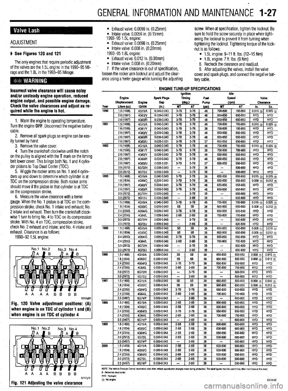
ADJUSTMENT
u See Figures 120 and 121
The only engines that require periodic adjustment
of the valves are the 1.5L engine in the 1990-95 Mi-
rage and the 1.8L in the 1993-95 Mirage.
Incorrect valve clearance will cause noisy
and/or unsteady engine operation, reduced
engine output, and possible engine damage.
Check the valve clearances and adjust as re-
quired while the engine is hot.
1. Warm the engine to operating temperature.
Turn the engine OFF. Disconnect the negative battery
cable.
2. Remove all spark plugs so engine can be eas-
ily turned by hand
3. Remove the valve cover.
4. Turn the crankshaft clockwise until the notch
on the pulley is aligned with the
T mark on the timing
belt lower cover. This brings both No. 1 and 4 cylin-
der pistons to Top Dead Center (TDC).
5. Wiggle the rocker arms on No. 1 and 4 cylin-
ders up and down to determine which cylinder is at
TDC on the compression stroke. Both rocker arms
should move if the piston in that cylinder is at TDC
on the compression stroke.
6. Measure the valve clearance with a feeler
gauge. When the No. 1 piston is at TDC on the com-
pression stroke, check No. 1 intake and
exhaust; No.
2 intake and exhaust. Then turn the crankshaft clock-
wise 1 turn to bring No. 4 to TDC on its compression
stroke. With No. 4 on TDC, compression stroke,
check No. 2 exhaust and intake; and No. 4 intake and
exhaust. Clearance is as follows:
1990-92 1.5L engine:
No.1 No.2
No.3 No.4
when engine is on TDC of cylinder 1 and (B) when engine is on TDC of cylinder 4
No.1 No.2
No.3 No.4
AA AA BB BB
93151g10 Fig. 121 Adjusting the valve clearance
l Exhaust valve: 0.0098 in. (0.25mm) screw. When at specification, tighten the locknut. Be l Intake valve: 0.0059 in. (0.15mm)
1993-95 1.5L engine: sure to hold the screw securely in place when tight-
l Exhaust valve: 0.0098 in. (0.25mm) ening the locknut to prevent it from turning when
* Intake valve: 0.008 in. (0.20mm) tightening the locknut. Tightening torque of the lock-
nut is as follows:
1993-95 1.8L engine:
l Exhaust valve: 0.012 in. (0.30mm) l 1.5L engine: 9-11 ft. Ibs. (12-15 Nm)
l Intake valve: 0.008 in. (0.20mm) l 1.8L engine: 7 ft. Ibs. (9 Nm)
8. Recheck the clearance and readjust.
7. If the valve clearance is out of specification,
9. After adjusting the valves, install the valve
loosen the rocker arm locknut and adjust the clear-
ante using a feeler gauge while turning the adjusting cover and spark plugs, and connect the negative bat-
tery cable.
Engine
ENGINE TUNE-UP SPECIFICATIONS Ignition
Spark Plugs liming
Fuel Idle
Speed Valve
Displacement
Engine
Gap (as.) Pump (rpm)
Clearance
Page 63 of 408
3-2 ENGINEANDENGINEOVERHAUL
REMOVAL &INSTALLATION
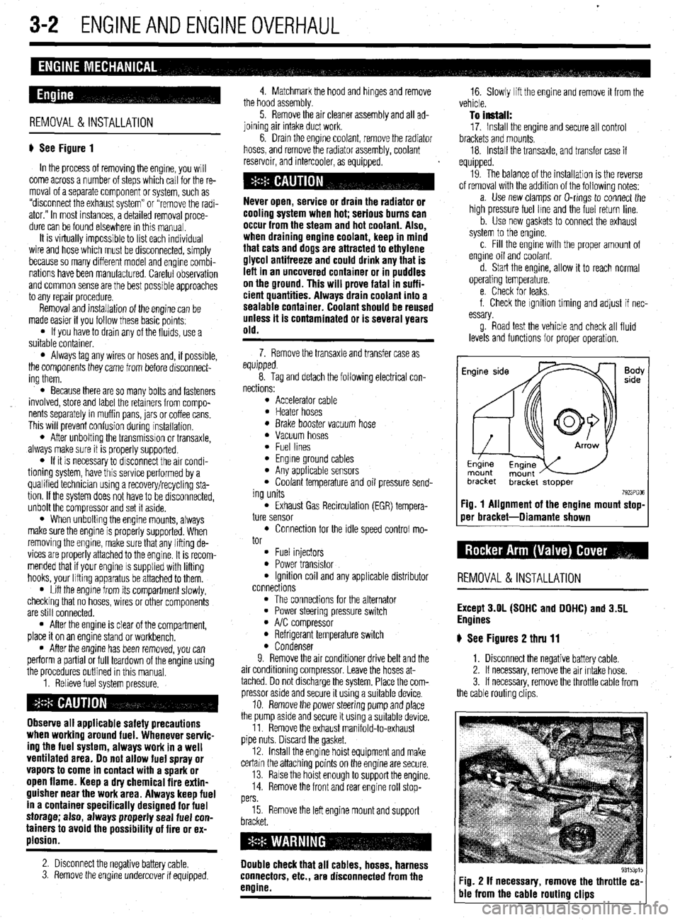
# See Figure 1
In the process of removing the engine, you will
come across a number of steps which call for the re-
moval of a separate component or system, such as
“disconnect the exhaust system” or “remove the radi-
ator.” In most instances, a detailed removal proce-
dure can be found elsewhere in this manual.
It is virtually impossible to list each individual
wire and hose which must be disconnected, simply
because so many different model and engrne combi-
nations have been manufactured Careful observation
and common sense are the best possible approaches
to any repair procedure.
Removal and installation of the engine can be
made easier if you follow these basic points:
l If you have to drain any of the fluids, use a
suitable container.
l Always tag any wires or hoses and, if possrble,
the components they came from before disconnect-
ing them.
l Because there are so many bolts and fasteners
involved, store and label the retainers from compo-
nents separately in muffin pans, jars or coffee cans.
This will prevent confusion during installatron.
l After unbolting the transmisston or transaxle,
always make sure it is properly supported.
l If it is necessary to disconnect the air condi-
tioning system, have this service performed by a
qualified technician using a recovery/recycling sta-
tion If the system does not have to be disconnected,
unbolt the compressor and set it aside.
l When unbolting the engine mounts, always
make sure the engine is properly supported. When
removing the engine, make sure that any lifting de-
vices are properly attached to the engine. It is recom-
mended that if your engine IS supplied with lifting
hooks, your lifting apparatus be attached to them.
l Lift the engine from its compartment slowly,
checking that no hoses, wires or other components
are still connected.
l After the engine is clear of the compartment,
place it on an engine stand or workbench.
l After the engine has been removed, you can
perform a partial or full teardown of the engine using
the procedures outlined in this manual.
1. Relieve fuel system pressure.
Observe all applicable safety precautions
when working around fuel. Whenever servic-
ing the fuel system, always work in a well
ventilated area. Do not allow fuel spray or
vapors to come in contact with a spark or
open flame. Keep a dry chemical fire extin-
guisher near the work area. Always keep fuel
in a container specifically designed for fuel
storage; also, always properly seal fuel con-
tainers to avoid the possibility of fire or ex-
plosion.
2. Disconnect the negative battery cable.
3. Remove the engine undercover if equipped. 4. Matchmark the hood and hinges and remove
the hood assembly.
5. Remove the air cleaner assembly and all ad-
joining air intake duct work.
6. Drain the engine coolant, remove the radiator
hoses, and remove the radiator assembly, coolant
reservoir, and intercooler, as equipped.
cooling system when hot; serious burns can
occur from the steam and hot coolant. Also,
when draining engine coolant, keep in mind
that cats and dogs are attracted to ethylene
glycol antifreeze and could drink any that is
left in an uncovered container or in puddles
on the ground. This will prove fatal in suffi-
cient quantities. Always drain coolant into a
sealable container. Coolant should be reused
unless it is contaminated or is several years
old.
7. Remove the transaxle and transfer case as
equipped.
8. Tag and detach the following electrical con-
nections:
l Accelerator cable l Heater hoses l Brake booster vacuum hose l Vacuum hoses l Fuel lines l Engine ground cables l Any applicable sensors l Coolant temperature and oil pressure send-
ing units
l Exhaust Gas Recirculation (EGR) tempera-
ture sensor
l Connection for the idle speed control mo-
tor
l Fuel injectors l Power transistor l Ignition coil and any applicable distributor
connections
l The connections for the alternator l Power steering pressure switch l A/C compressor l Refrigerant temperature switch l Condenser
9. Remove the air conditioner drive belt and the
air conditioning compressor. Leave the hoses at-
tached. Do not discharge the system. Place the com-
pressor aside and secure it using a suitable device.
10. Remove the power steering pump and place
the pump asrde and secure it using a surtable device.
11. Remove the exhaust manifold-to-exhaust
pipe nuts. Discard the gasket.
12. Install the engine hoist equipment and make
certain the attaching points on the engine are secure.
13. Raise the hoist enough to support the engine.
14. Remove the front and rear engine roll stop-
pers
15. Remove the left engine mount and support
Double check that all cables, hoses, harness
connectors, etc., are disconnected from the
engine.
16. Slowly lift the engine and remove it from the
vehicle.
To install:
17. Install the engine and secure all control
brackets and mounts.
18. Install the transaxle, and transfer case if
equipped.
19. The balance of the installation is the reverse
of removal with the addition of the following notes:
a. Use new clamps or O-rings to connect the
high pressure fuel lme and the fuel return line.
b. Use new gaskets to connect the exhaust
system to the engine.
c. Fill the engine with the proper amount of
engine oil and coolant.
d. Start the engine, allow it to reach normal
operating temperature.
e. Check for leaks.
f. Check the ignition timing and adjust if nec-
essary.
g. Road test the vehicle and check all fluid
levels and functions for proper operation.
Fig. 1 Alignment of the engine mount stop-
oer bracket-Diamante shown
REMOVAL &INSTALLATION
Except 3.OL (SOHC and DOHC) and 3.5L
Engines
# See Figures 2 thru 11
1. Disconnect the negative battery cable.
2. If necessary, remove the air intake hose.
3. If necessary, remove the throttle cable from
the cable routing clips.
Fig. 2 If necessary, remove the throttle ca-
ble from the cable routing clips
Page 74 of 408
ENGINEANDENGINEOVERHAUL 3-13
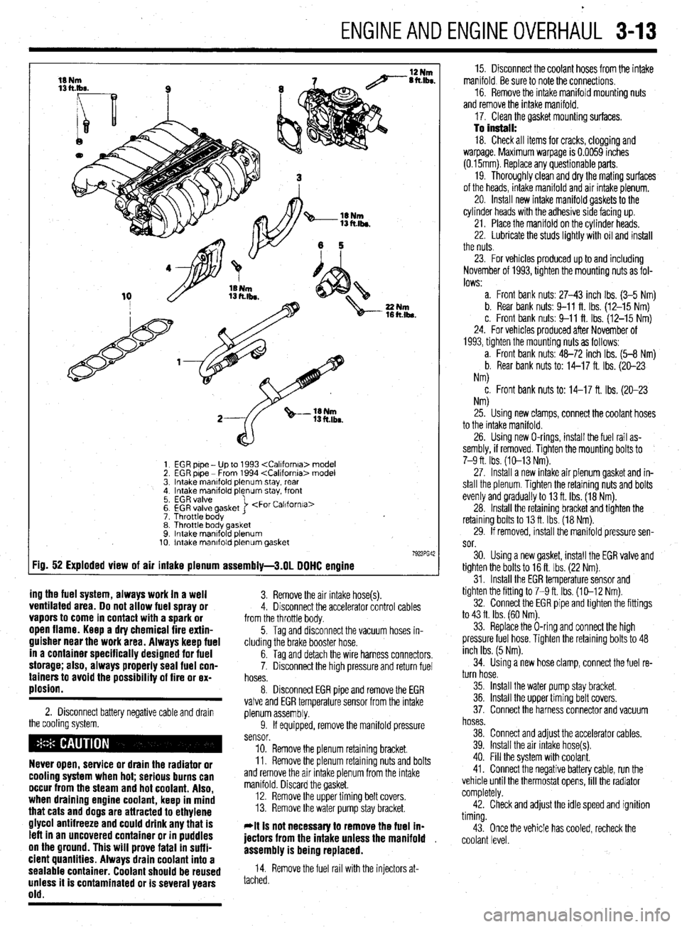
EGR pipe - Up to 1993
EGR pipe - From 1994
Intake manlfold plenum stay, rear
Intake manifold plenum stay. front
EGR valve
EGR valve gasket
Throttle body >
Throttle body gasket
Intake mantfold plenum
Intake manifold plenum gasket
:ig. 52 Exploded view of air intake plenum assembly-3.01 DOHC engine
ing the fuel system, always work in a well
3. Remove the air intake hose(s). ventilated area. Do not allow fuel spray or 4. Disconnect the accelerator control cables vapors to come in contact with a spark or from the throttle body. open flame. Keep a dry chemical fire extin-
guisher near the work area. Always keep fuel
in a container specifically designed for fuel
storage; also, always properly seal fuel con-
tainers to avoid the possibility of fire or ex-
plosion.
2. Disconnect battery negative cable and drawn
the cooling system.
Never open, service or drain the radiator or
cooling system when hot; serious burns can
occur from the steam and hot coolant. Also,
when draining engine coolant, keep in mind
that cats and dogs are attracted to ethylene
glycol antifreeze and could drink any that is
left in an uncovered container or in puddles
on the ground. This will prove fatal in suffi-
cient quantities. Always drain coolant into a
sealable container. Coolant should be reused
unless it is contaminated or is several years
old.
5. Tag and disconnect the vacuum hoses in-
cluding the brake booster hose.
6. Tag and detach the wire harness connectors,
7. Disconnect the high pressure and return fuel
hoses.
8. Disconnect EGR pipe and remove the EGR
valve and EGR temperature sensor from the intake
plenum assembly.
9. If equipped, remove the manifold pressure
sensor.
10. Remove the plenum retaining bracket.
11. Remove the plenum retaining nuts and bolts
and remove the air intake plenum from the intake
manifold. Discard the gasket.
12. Remove the upper timing belt covers.
13. Remove the water pump stay bracket.
*It is not necessav to remove the fuel ln-
jectors from the intake unless the manifold ,
assembly is being replaced.
14. Remove the fuel rail with the injectors at-
tached. 15. Disconnect the coolant hoses from the intake
manifold. Be sure to note the connections.
16. Remove the intake manifold mounting nuts
and remove the intake manifold.
17. Clean the gasket mounting surfaces.
To install: 18. Check all items for cracks, clogging and
warpage. Maximum warpage is 0.0059 inches
(0.15mm). Replace any questionable parts.
19. Thoroughly clean and dry the mating surfaces
of the heads, intake manifold and air intake plenum.
20. Install new intake manifold gaskets to the
cylinder heads with the adhesive side facing up.
21. Place the manifold on the cylinder heads.
22. Lubricate the studs lightly with oil and install
the nuts.
23. For vehicles produced up to and including
November of 1993, tighten the mounting nuts as fol-
lows:
a. Front bank nuts: 27-43 inch Ibs. (3-5 Nm)
b. Rear bank nuts: 9-11 ft. Ibs. (12-15 Nm)
c. Front bank nuts: 9-11 ft. Ibs. (12-15 Nm)
24. For vehicles produced after November of
1993, tighten the mounting nuts as follows:
a. Front bank nuts: 48-72 inch Ibs. (5-8 Nm)
b. Rear bank nuts to: 14-17 ft. Ibs. (20-23
Nm)
c. Front bank nuts to: 14-17 ft. Ibs. (20-23
NM
25. Using new clamps, connect the coolant hoses
to the intake manifold.
26. Using new O-rings, install the fuel rail as-
sembly, if removed. Tighten the mounting bolts to
7-9 ft. Ibs. (10-13 Nm).
27. Install a new intake air plenum gasket and in-
stall the plenum. Tighten the retaining nuts and bolts
evenly and gradually to 13 ft. Ibs. (18 Nm).
28. Install the retaining bracket and tighten the
retaining bolts to 13 ft. Ibs. (18 Nm).
29. If removed, install the manifold pressure sen-
sor.
30. Using a new gasket, install the EGR valve and
tighten the bolts to 16 ft. Ibs. (22 Nm).
31. Install the EGR temperature sensor and
tighten the fitting to 7-9 ft. Ibs. (10-12 Nm).
32. Connect the EGR pipe and tighten the fittings
to 43 ft. Ibs. (60 Nm).
33. Replace the O-ring and connect the high
pressure fuel hose. Tighten the retaining bolts to 48
inch Ibs. (5 Nm).
34. Using a new hose clamp, connect the fuel re-
turn hose.
35. Install the water pump stay bracket.
36. Install the upper timing belt covers.
37. Connect the harness connector and vacuum
hoses.
38. Connect and adjust the accelerator cables.
39. Install the air intake hose(s).
40. Fill the system with coolant.
41. Connect the negative battery cable, run the
vehicle until the thermostat opens, fill the radiator
completely.
42. Check and adjust the idle speed and ignition
timing.
43. Once the vehicle has cooled, recheck the
coolant level.
Page 75 of 408
.
3-14 ENGINEANDENGINEOVERHAUL
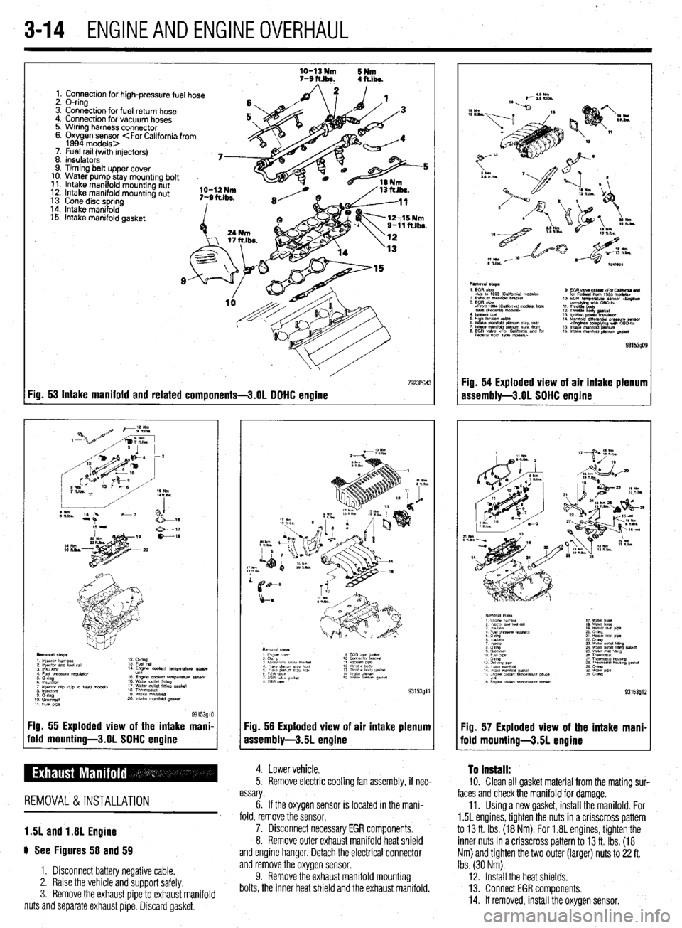
1. Connection for high-pressure fuel hose
2. O-ring
3. Connection for fuel return hose
4. Connection for vacuum hoses
5. Wrring harness connector
6. Oxy
P en sensor
7. Fuel rail (with injectors)
8 Insulators
9. Timing belt upper cover
10. Water pump stay mountrng bolt
11. Intake manifold mounting nut
12. Intake manifold mounting nut
13 Cone disc spring
14. Intake manrfold
15. intake manifold gasket
:ig. 53 Intake manifold and related components-3.01 DDHC enaine
Fig. 55 Exploded view of the intake mani- :ig. 56 Exploded view of
fold mounting-3.01 SDHC engine
Issembly-3.5L engine air intake plenum
5. Remove electric cooling fan assembly, if nec- 4. Lower vehicle. To install: 10. Clean all gasket material from the mating sur-
REMOVAL &INSTALLATION
1.5L and 1.8L Engine
# See Figures 58 and 59 essary. faces and check the manifold for damage.
6. If the oxygen sensor is located in the mani- 11. Using a new gasket, install the manifold. For
fold, remove the sensor. 1.5L engines, tighten the nuts in a crisscross pattern
7. Disconnect necessary EGR components. to 13 ft. Ibs. (18 Nm). For 1.8L engines, tighten the
8. Remove outer exhaust manifold heat shield inner nuts in a crisscross pattern to 13 ft. Ibs. (18
and engine hanger. Detach the electrical connector Nm) and tighten the two outer (larger) nuts to 22 ft.
1. Disconnect battery negative cable.
2. Raise the vehicle and support safely
3. Remove the exhaust pipe to exhaust manifold
nuts and separate exhaust pipe. Discard gasket, and remove the oxygen sensor.
9. Remove the exhaust manifold mounting
bolts, the inner heat shield and the exhaust manifold. Ibs. (30 Nm).
12. Install the heat shields,
13. Connect EGR components.
14. If removed, install the oxygen sensor.
Page 84 of 408
ENGlNEANDENGlNEOVERHAiL 3-23
8. Remove the camshaft and silent shaft timing
belts. Refer to the timing belt procedure in this sec-
tion
9. Remove the A/C belt idler pulley and pulley
bracket.
10. Remove the alternator brace,
11. Remove the water pump, gasket and O-ring
where the water inlet pipe(s) joins the pump.
To install:
12. Thoroughly clean both gasket surfaces of the
water pump and block.
13. Install a new O-ring into the groove on the
front end of the water inlet pipe and wet with clean
antifreeze only. Do not apply oils or grease to the O-
ring.
14. Using a new gasket, install the water pump
assembly. Tighten bolts with the head mark 4 to 10
ft Ibs. (14 Nm) and bolts with the head mark 7 to 18
ft. Ibs. (24 Nm).
15. Install the A/C pulley and pulley bracket,
16. Install the timing belts. Refer to the timing
belt procedure in this section.
17. Install the engine drive belts.
18. Install the engine mount bracket.
19. Install the engine undercover,
20. Fill the system with coolant.
21. Connect the negative battery cable, run the
vehicle until the thermostat opens and fill the radiator
completely.
22. Once the vehicle has cooled, recheck the
coolant level.
3.OL and 3.5L Engines
# See Figure 109
1. Disconnect the negative battery cable,
2. Drain the cooling system.
Never open, service or drain the radiator or
cooling system when hot; serious burns can
occur from the steam and hot coolant. Also,
when draining engine coolant, keep in mind
that cats and dogs are attracted to ethylene
glycol antifreeze and could drink any that is
left in an uncovered container or in puddles
on the ground. This will prove fatal in suffi-
cient quantities. Always drain coolant into a
sealable container. Coolant should be reused
unless it is contaminated or is several years
old.
3. Remove the engine undercover.
4. Disconnect the clamp bolt from the power
steering hose.
5. Support the engine with the appropriate
equipment and remove the engine mount bracket.
6. Remove the timing belt. Refer to the timing
belt procedure in this section.
7. Disconnect the coolant hoses from the pump,
if equipped.
8. Remove the alternator brace.
*The water pump bolts are different in size.
Note their locations for installation.
9. Remove the water pump, gasket and O-ring
where the water inlet pipe joins the pump.
To install: 10. Thoroughly clean both gasket surfaces of the
water pump and block.
11. Install a new O-ring into the groove on the
front end of the water inlet pipe. Do not apply oils or
grease to the O-ring. Wet with water only.
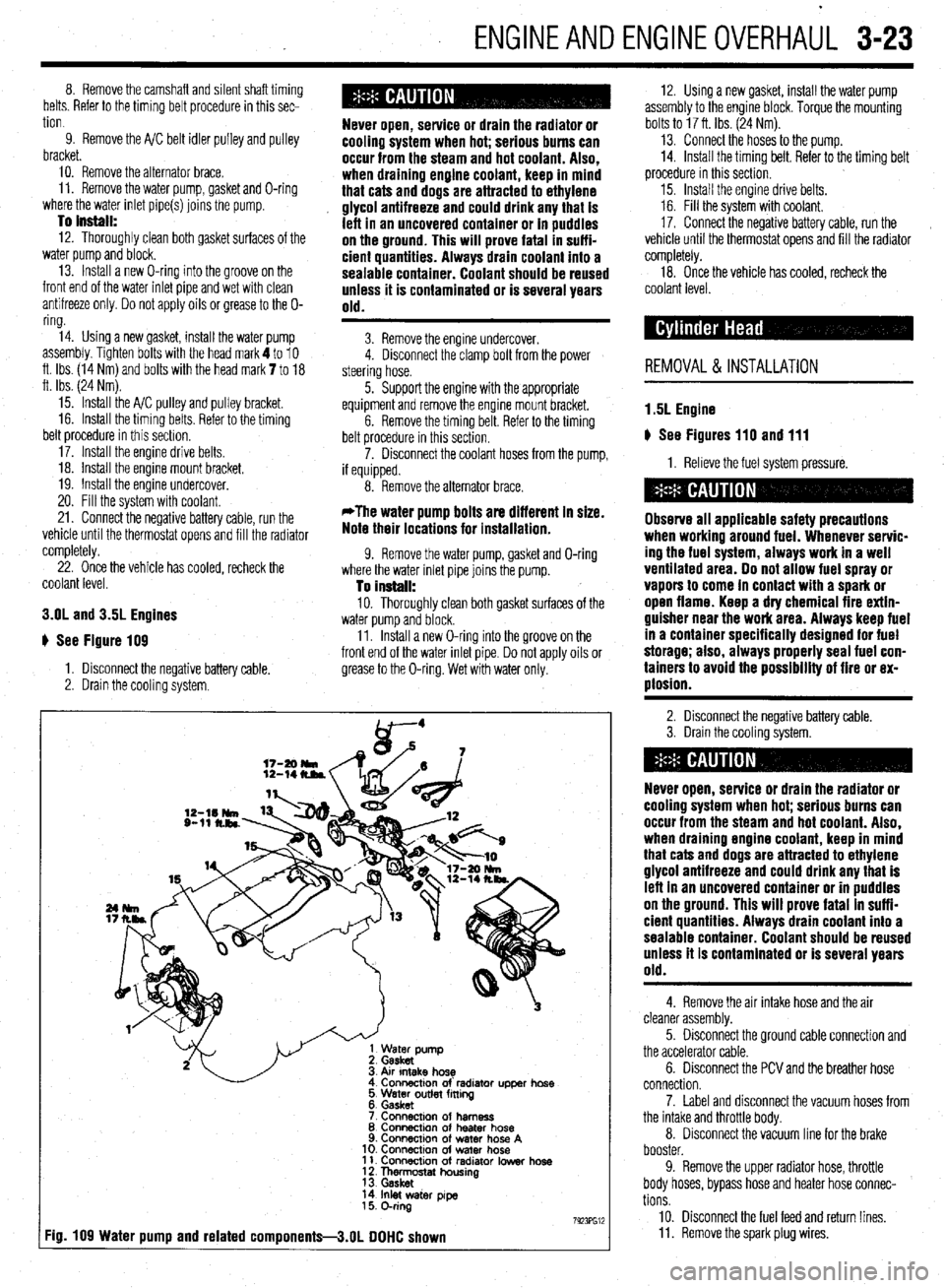
Atr Intake hose
Connactlon of’ radlator upper hose
5 Water outlet fming
6. Gasket
7 Connacmn of harness
8 Connection of heater hose
9. Connection of water hose A
10. ConnectIon of water hose
11. Connection of radiator Iowar hose
1 f Thn&ostat housing
14 Inlet water pye
15 O-ring
7923Fw :ig. 109 Water pump and related components-3.01 DOHC shown
12. Using a new gasket, install the water pump
assembly to the engine block. Torque the mounting
bolts to 17 ft. Ibs. (24 Nm).
13. Connect the hoses to the pump.
14. Install the timing belt. Refer to the timing belt
procedure in this section.
15. Install the engine drive belts.
16. Fill the system with coolant.
17. Connect the negative battery cable, run the
vehicle until the thermostat opens and fill the radiator
completely.
18. Once the vehicle has cooled, recheck the
coolant level.
REMOVAL & INSTALLATION
1.5L Engine
u See Figures 110 and 111
1. Relieve the fuel system pressure.
Observe all applicable safety precautions
when working around fuel. Whenever servic-
ing the fuel system, always work in a well
ventilated area. Do not allow fuel spray or
vapors to come in contact with a spark or
open flame. Keep a dry chemical fire extin-
guisher near the work area. Always keep fuel
in a container specifically designed for fuel
storage; also, always properly seal fuel con-
tainers to avoid the possibility of fire or ex-
plosion.
2. Disconnect the negative battery cable.
3. Drain the cooling system.
Never open, service or drain the radiator or
cooling system when hot; serious burns can
occur from the steam and hot coolant. Also,
when draining engine coolant, keep in mind
that cats and dogs are attracted to ethylene
glycol antifreeze and could drink any that is
left in an uncovered container or in puddles
on the ground. This will prove fatal in suffi-
cient quantities. Always drain coolant into a
sealable container. Coolant should be reused
unless it is contaminated or is several years
old.
4. Remove the air intake hose and the air
cleaner assembly.
5. Disconnect the ground cable connection and
the accelerator cable.
6. Disconnect the PCV and the breather hose
connection.
7. Label and disconnect the vacuum hoses from
the intake and throttle body.
8. Disconnect the vacuum line for the brake
booster.
9. Remove the upper radiator hose, throttle
body hoses, bypass hose and heater hose connec-
tions
10. Disconnect the fuel feed and return lines.
11. Remove the spark plug wires.
Page 90 of 408
ENGINEANDENGINEOVERHAUL 3-29
l HOzS sensor l ECT gauge sender l ECT sensor l MAP sensor l IAT sensor l TP sensor l IAC motor l injector harness l ignition coil l CMP sensor l EGR solenoid valve
33. Install the spark plug wires and cover,
34. Replace the O-rings and connect the fuel
lines.
35. Install the air cleaner and intake hose. Con-
nect the breather hose.
36. Fill the cooling system.
37. Connect the negative battery cable
3.01 DDHC Engine
ti See Figures 132 and 133
1. Relieve fuel system pressure. Disconnect the
negative battery cable.
2. Drain the cooling system.
Never open, service or drain the radiator or
cooling system when hot; serious burns can
occur from the steam and hot coolant. Also,
when draining engine coolant, keep in mind
that cats and dogs are attracted to ethylene
glycol antifreeze and could drink any that is
left in an uncovered container or in puddles
on the ground. This will prove fatal in suffi-
cient quantltles. Always drain coolant into a
sealable container. Coolant should be reused
unless it is contaminated or is several years
old.
3. Remove the air intake hoses.
4. Remove air intake plenum and intake mani-
fold.
5. Remove the exhaust manifold.
6. Remove the timing belt. Refer to the timing
belt procedure in this section.
7. Remove the breather hose.
8. Remove the spark plug wire center cover and
remove the spark plug wires.
9. Remove the rocker covers.
10. Remove the intake camshaft sprockets.
11. Remove the rear timing belt cover.
12. Remove the ignition coil assembly.
13. Disconnect all water hoses from the thermo-
stat housing and remove the housing.
14. Disconnect the water inlet from the front
head.
15. Loosen the cylinder head mounting bolts in
the reverse of the torque sequence and loosen the
bolts in three steps. Lift off the cylinder head assem-
bly and remove the head gasket.
To install: 16. Thoroughly clean the sealing surfaces of the
head and block.
17. Place a new head gasket on the cylinder
block with the identification marks in the front top
(upward) position. Do not use sealer on the gasket,
18. Carefully install the cylinder head on the
block. Be sure the head bolt washers are installed
with the chamfered edge upward. Using three even
steps, torque the head bolts in sequence, to 76-83 ft.
Ibs. (105-115 Nm).
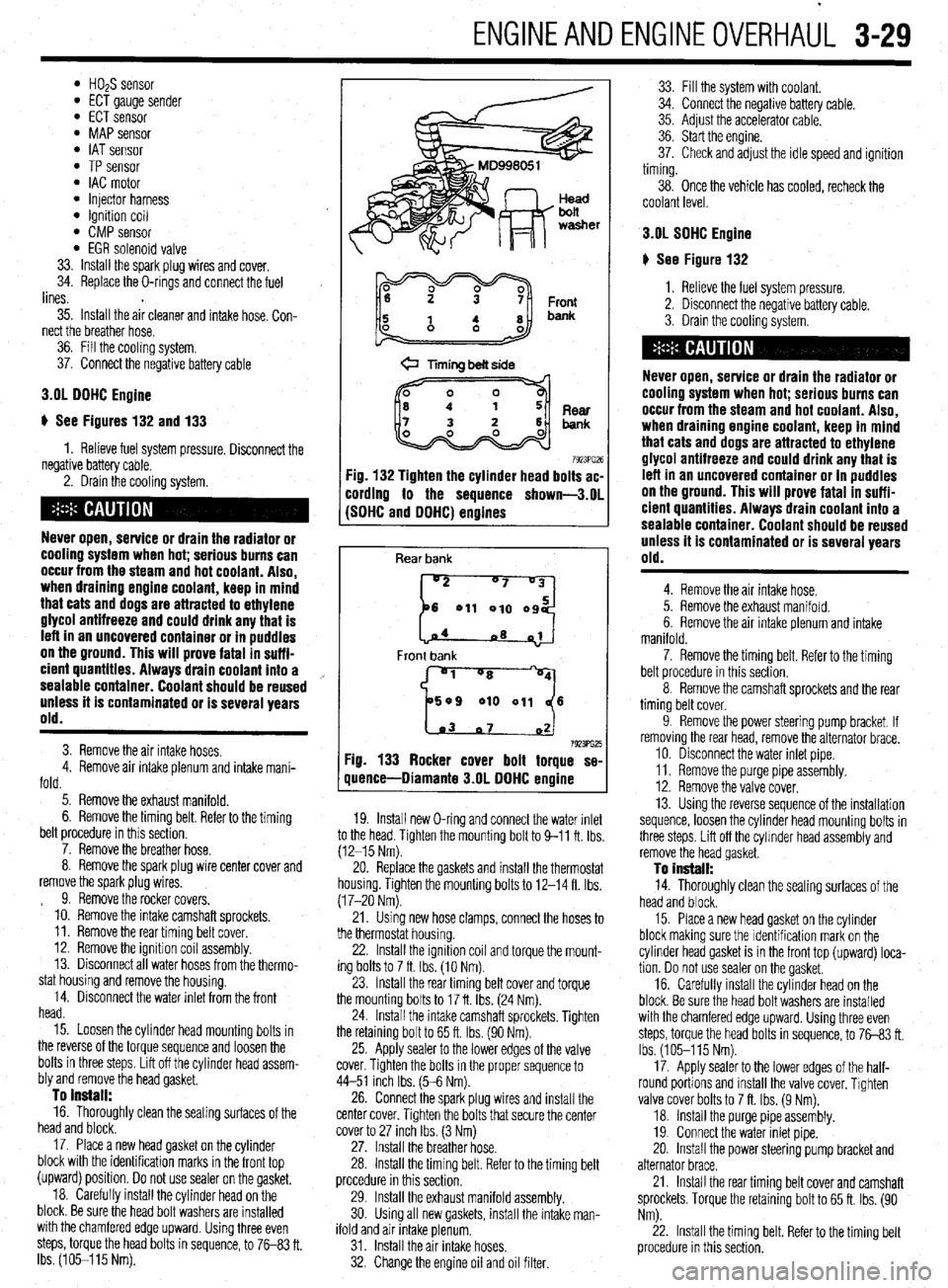
@ Timing belt side
7923PG26 :ig. 132 Tighten the cylinder head bolts ac-
:ording to the sequence shown-3.01
SDHC and DDHC) engines
Rear bank
[::od
04
~8 01
Front bank
'1 "8
509 010 011 6
1.03 07 02 7923ffi25 Fig. 133 Rocker cover bolt torque se-
quence-Diamante 3.OL DDHC engine
19. Install new O-ring and connect the water inlet
to the head. Tighten the mounting bolt to 9-11 ft. Ibs
(12-15 Nm).
20. Replace the gaskets and install the thermostat
housing. Tighten the mounting bolts to 12-14 ft. Ibs.
(17-20 Nm).
21. Using new hose clamps, connect the hoses to
the thermostat housing.
22. Install the Ignition coil and torque the mount-
ing bolts to 7 ft. Ibs. (10 Nm).
23. Install the rear timing belt cover and torque
the mounting bolts to 17 ft. Ibs. (24 Nm).
24. Install the intake camshaft sprockets. Tighten
the retaining bolt to 65 ft. Ibs. (90 Nm).
25. Apply sealer to the lower edges of the valve
cover. Tighten the bolts in the proper sequence to
44-51 inch Ibs. (5-6 Nm).
26. Connect the spark plug wires and install the
center cover. Tighten the bolts that secure the center
cover to 27 inch Ibs. (3 Nm)
27. Install the breather hose.
28. Install the timing belt. Refer to the timing belt
procedure in this section,
29. Install the exhaust manifold assembly.
30. Using all new gaskets, install the intake man-
ifold and air intake plenum.
31. Install the air intake hoses.
32. Change the engine oil and oil filter. 33. Fill the system wrth coolant.
34. Connect the negabve battery cable.
35. Adjust the accelerator cable.
36. Start the engine.
37. Check and adjust the idle speed and ignition
timing.
38. Once the vehicle has cooled, recheck the
coolant level.
3.OL SDHC Engine
# See Figure 132
1. Relieve the fuel system pressure.
2. Disconnect the negative battery cable.
3. Drain the cooling system.
Never open, service or drain the radiator or
cooling system when hot; serious burns can
occur from the steam and hot coolant. Also,
when draining engine coolant, keep in mind
that cats and dogs are attracted to ethylene
alvcol antifreeze and could drink any that is
Left in an uncovered container or in puddles
on the ground. This will Drove fatal in suff i-
cient quantities. Always drain coolant into a
sealable container. Coolant should be reused
Unless it is Contaminated or is several years
old.
4. Remove the air intake hose.
5. Remove the exhaust manifold.
6. Remove the air intake plenum and intake
manifold.
7. Remove the timing belt. Refer to the timing
belt procedure in this section.
8. Remove the camshaft sprockets and the rear
timing belt cover.
9. Remove the power steering pump bracket. If
removing the rear head, remove the alternator brace.
10. Disconnect the water inlet pipe.
11. Remove the purge pipe assembly.
12. Remove the valve cover,
13. Using the reverse sequence of the installation
sequence, loosen the cylinder head mounting bolts in
three steps. Lift off the cylmder head assembly and
remove the head gasket.
To install: 14. Thoroughly clean the sealing surfaces of the
head and block.
15. Place a new head gasket on the cylinder
block making sure the identification mark on the
cylrnder head gasket is in the front top (upward) loca-
tion. Do not use sealer on the gasket,
16. Carefully install the cylinder head on the
block. Be sure the head bolt washers are installed
with the chamfered edge upward. Using three even
steps, torque the head bolts in sequence, to 7683 ft.
Ibs. (105-115 Nm).
17. Apply sealer to the lower edges of the half-
round portions and install the valve cover. Tighten
valve cover bolts to 7 ft. Ibs. (9 Nm).
18. Install the purge pipe assembly.
19. Connect the water inlet pipe.
20. Install the power steering pump bracket and
alternator brace.
21. Install the rear timing belt cover and camshaft
sprockets. Torque the retaining bolt to 65 ft. Ibs. (90
Nm).
22. Install the timing belt. Refer to the timing belt
procedure in this section.
Page 118 of 408
ENGINEANDENGINEOVERHAUL 3-57
Anything that generates heat and/or friction WIII
eventually burn or wear out (for example, a light bulb
generates heat, therefore its life span is limited). With
this in mind, a running engine generates tremendous
amounts of both; friction is encountered by the mov-
ing and rotating parts inside the engine and heat is
created by friction and combustion of the fuel How-
ever, the engine has systems designed to help reduce
the effects of heat and friction and provide added
longevrty. The oiling system reduces the amount of
friction encountered by the moving parts inside the
engine, while the cooling system reduces heat cre-
ated by friction and combustion If either system is
not maintained, a break-down will be inevitable.
Therefore, you can see how regular maintenance can
affect the service life of your vehicle, If you do not
drain, flush and refill your cooling system at the
proper intervals, deposits WIII begin to accumulate in
the radiator, thereby reducing the amount of heat it
can extract from the coolant The same applies to
your oil and filter; If it is not changed often enough it
becomes laden with contaminates and is unable to
properly lubricate the engine. This increases friction
and wear.
There are a number of methods for evaluating the
condition of your engine. A compression test can re-
veal the condition of your pistons, piston rings,
cylinder bores, head gasket(s), valves and valve
seats. An oil pressure test can warn you of possible
engine bearing, or oil pump failures. Excessrve oil
consumption, evidence of oil in the engine air intake
area and/or bluish smoke from the tailpipe may indi-
cate worn piston rings, worn valve guides and/or
valve seals. As a general rule, an engine that uses no
more than one quart of oil every 1000 miles is in
good condition. Engines that use one quart of oil or
more in less than 1000 miles should first be checked
for oil leaks. If any oil leaks are present, have them
fixed before determining how much oil is consumed
by the engine, especrally if blue smoke is not visible
at the tailpipe
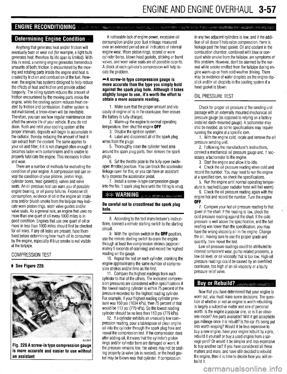
COMPRESSION TEST
# See Figure 226
tccs3801 Fig. 226 A screw-in type compression gauge
is more accurate and easier to use without
an assistant
A noticeable lack of engine power, excessive oil
consumption and/or poor fuel mileage measured
over an extended period are all indicators of internal
engine wear. Worn piston rings, scored or worn
cylinder bores, blown head gaskets, sticking or burnt
valves, and worn valve seats are all possible culprits.
A check of each cylinders compression WIII help lo-
cate the problem.
*A screw-in type compression gauge is
more accurate than the type you simply hold
against the spark plug hole. Although it takes
slightly longer to use, it’s worth the effort to
obtain a more accurate reading.
1 Make sure that the proper amount and vis-
cosity of engine oil is in the crankcase, then ensure
the battery is fully charged.
2. Warm-up the engine to normal operating
temperature, then shut the engine
OFF. 3. Disable the ignition system.
4. Label and disconnect all of the spark plug
wires from the plugs,
5. Thoroughly clean the cylinder head area
around the spark plug ports, then remove the spark
plugs.
6. Set the throttle plate to the fully open (wide-
open throttle) position You can block the accelerator
linkage open for this, or you can have an assistant
fully depress the accelerator pedal.
7. Install a screw-in type compression gauge
into the No. 1 spark plug hole until the fitting is snug.
Be careful not to crossthread the spark plug
hole.
8. According to the tool manufacturers instruc-
tions, connect a remote starting switch to the starting
circuit.
9. With the ignition switch in the
OFF position,
use the remote starting switch to crank the engine
through at least five compression strokes (approxi-
mately 5 seconds of cranking) and record the highest
reading on the gauge
10. Repeat the test on each cylinder, cranking the
engine approximately the same number of compres-
sion strokes and/or time as the first.
11. Compare the hrghest readings from each
cylinder to that of the others. The indicated compres-
sion pressures are considered within specifications if
the lowest reading cylinder is within 75 percent of the
pressure recorded for the highest reading cylinder
For example, if your highest reading cylinder pres-
sure was 150 psi (1034 kPa), then 75 percent of that
would be 113 psi (779 kPa). So the lowest reading
cylinder should be no less than 113 psi (779 kPa).
12. If a cylinder exhibits an unusually low com-
pression reading, pour a tablespoon of clean engine
oil into the cylinder through the spark plug hole and
repeat the compression test. If the compression rises
after adding oil, it means that the cylinder’s piston
rings and/or cylinder bore are damaged or worn, If
the pressure remains low, the valves may not be seat-
ing properly (a valve job is needed), or the head gas-
ket may be blown near that cylinder. If compression in any two adjacent cylinders is low, and if the addi-
tion of oil doesn’t help raise compression, there is
leakage past the head gasket. Oil and coolant in the
combustion chamber, combined with blue or con-
stant white smoke from the tailpipe, are symptoms of
this problem. However, don’t be alarmed by the nor-
mal white smoke emitted from the tailpipe during en-
gine warm-up or from cold weather driving. There
may be evidence of water droplets on the engine dip-
stick and/or oil droplets in the cooling system if a
head gasket is blown.
OIL PRESSURETEST
Check for proper oil pressure at the sending unit
passage with an externally mounted mechanical oil
pressure gauge (as opposed to relying on a factory
Installed dash-mounted gauge). A tachometer may
also be needed, as some specifications may require
running the engine at a specific rpm.
1. With the engine cold, locate and remove the oil
pressure sending unit.
2. Followrng the manufacturers instructions,
connect a mechanical oil pressure gauge and, if nec-
essary, a tachometer to the engine.
3 Start the engine and allow it to idle.
4 Check the oil pressure reading when cold and
record the number. You may need to run the engine
at a specified rpm, so check the specifications,
5. Run the engine until normal operating temper-
ature is reached (upper radiator hose will feel warm)
6. Check the oil pressure reading again with the
engine hot and record the number. Turn the engine
OFF. 7. Compare your hot oil pressure reading to that
given in the chart If the reading is low, check the
cold pressure reading against the chart. If the cold
pressure IS well above the specification, and the hot
reading was lower than the specification, you may
have the wrong viscosity oil in the engine. Change
the oil, making sure to use the proper grade and
quantity, then repeat the test.
Low oil pressure readings could be attributed to
internal component wear, pump related problems, a
low oil level, or oil viscosity that is too low. High oil
pressure readings could be caused by an overfilled
crankcase, too htgh of an oil viscosity or a faulty
pressure relief valve.
Now that you have determined that your engine is
worn out, you must make some decisions. The ques-
tion of whether or not an engine IS worth rebuilding
is largely a subjective matter and one of personal
worth. Is the engine a popular one, or IS it an obso-
lete model? Are parts available? Will it get acceptable
gas mileage once It is rebuilt? Is the car its being put
into worth keeping? Would it be less expensive to
buy a new engine, have your engine rebuilt by a pro,
rebuild it yourself or buy a used engine from a sal-
vage yard? Or would It be simpler and less expensive
to buy another car? If you have considered all these
matters and more, and have still decided to rebuild
the engine, then it is time to decide how you will re-
build it.
Page 161 of 408
.
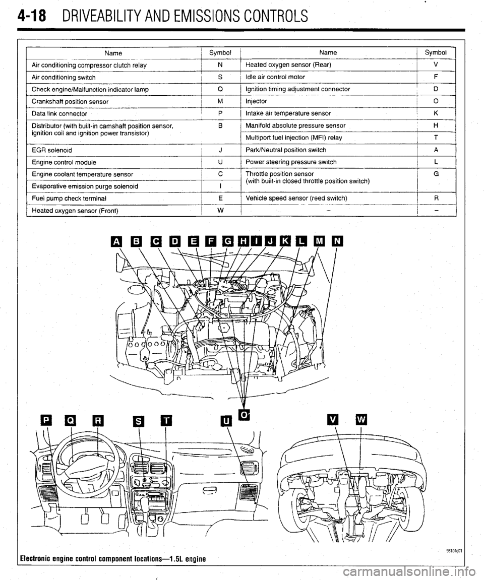
4-18 DRIVEABILITYAND EMISSIONS CONTROLS
Name ; Symbol Name j Symbol
I
Arr conditioning compressor clutch relay ; N Heated oxygen sensor (Rear)
j ”
Air condrtioning swatch , s 1 Idle air control motor
/ F
/
Check engrne/Malfunction Indicator lamp
/ Q lgnrtion trmrng adjustment connector
j D
Crankshaft position sensor / M Injector
! O
Data link connector
j p Intake air temperature sensor / K
Distributor (wrth bulk-in camshaft position sensor, , B Manifold absolute pressure sensor
ignition coil and rgnrtron power transistor) I 1 H
Multrport fuel in]ectron (MFI) relay
i T
EGR solenord
i J PaWNeutral positron switch j A
Engine control module
I u I Power steering pressure switch
Engine coolant temperature sensor c / Throttle position sensor
Evaporative emission purge solenoid
I I I (with burl&In closed throttle position switch) / L _
/ G
I
I
- Fuel pump check terminal /
I j E i Vehicle speed sensor (reed switch)
/ R
Heated oxygen sensor (Front)
I w I
i -
Ilectronic engine control component locations-l 51 engine 93154go1
Page 162 of 408
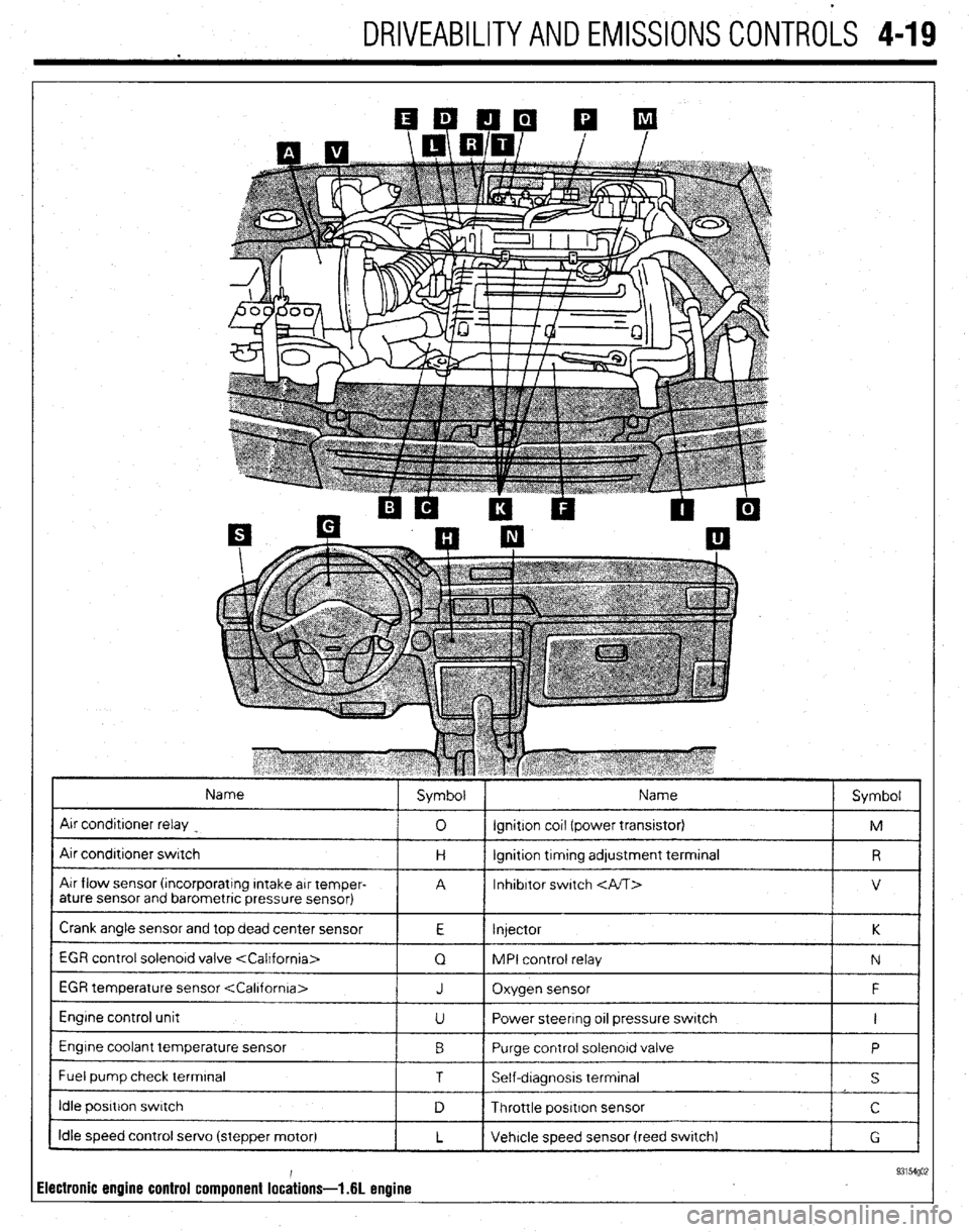
DRIVEABILITYAND EMISSIONS CONTROLS 4-19
Name
Air conditroner relay
Air condrtroner switch
Air flow sensor (rncorporatrng Intake arr temper-
ature sensor and barometric pressure sensor) Symbol Name
Symbol
0 ignition cot1 (power transrstor)
M
H lgnrtion trmtng adjustment terminal
R
A Inhibitor switch
V
Crank angle sensor and top dead center sensor
E Injector K
1 EGR control solenord valve
1 Q 1 MPI control relay
1 N 1
EGR temperature sensor
Engine control unit
Engine coolant temperature sensor
I Fuel pump check terminal J Oxygen sensor F
U Power steering 011 pressure switch I
0 Purge control solenord valve
P
1 T I Self-dragnosis terminal
I s I
I idle posrtron swatch
1 D 1 Throttle positron sensor I c I
Idle speed control servo (stepper motor)
L Vehicle speed sensor (reed swatch)
G
ilectronic engine control component lochions- .6L enuine 93154go;
Page 163 of 408
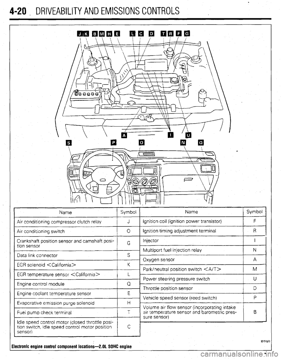
4-20 , DRIVEABILITYAND EMISSIONS CONTROLS
Name Symbol Name Symbol
Air conditioning compressor clutch relay J Ignition coil (ignition power transistor) F
Air conditlonrng switch 0 Ignition trming adjustment terminal R
Crankshaft positron sensor and camshaft posi- Injector I
tion sensor G
~ Multiport fuel injection relay N
Data link connector s ’
- Oxygen sensor A
EGR solenoid
~ Park/neutral positron switch M
EGR temperature sensor
_ Power steering pressure switch
U
Engine control module Q
~ Throttle position sensor
D
Engrne coolant temperature sensor E
Vehicle speed sensor (reed switch) P
Evaporative emrsslon purge solenoid H -
Volume air flow sensor (incorporating intake
Fuel pump check terminal T arr temperature sensor and barometric pres- B
- sure sensor)
Idle speed control motor (closed throttle POW
tron swatch, tdle speed control motor positron
sensor)
! c
93154go: Electronic engine control component locations-2.01 SOHC engine