change wheel MITSUBISHI DIAMANTE 1900 Repair Manual
[x] Cancel search | Manufacturer: MITSUBISHI, Model Year: 1900, Model line: DIAMANTE, Model: MITSUBISHI DIAMANTE 1900Pages: 408, PDF Size: 71.03 MB
Page 1 of 408
HOW TO USE THIS BOOK 1-2
WHERE TOBEGIN l-2
AVOIDINGTROUBLE 1-2
MAINTENANCEORREPAIR? 1-2
AVOIDINGTHEMOSTCOMMONMISTAKES l-2
TOOLS AND EQUIPMENT 1-2
SPECIALTOOLS l-4
YOUR VEHICLE SAFELY 1-4
DON'TS l-6
FASTENERS, MEASUREMENTS AND
CONVERSIONS l-6
BOLTS,NUTSANDOTHERTHREADED
RETAINERS 1-6
TORQUE l-7
TORQUEWRENCHES l-7
TORQUEANGLEMETERS 1-9
STANDARDANDMETRIC MEASUREMENTS l-9
SERIAL NUMBER IDENTIFICATION l-10
VEHICLE IDENTIFICATION NUMBER l-10
ENGINE IDENTIFICATION NUMBER I-10
TRANSAXLEIDENTIFICATION I-10
DRlVEAXLE(AWDGALANTONLY) l-10
TRANSFERCASE(AWDGALANTONLY) l-10
ROUTINE MAINTENANCE AND TUNE-UP l-14
AIRCLEANER(ELEMENT) 1-14
REMOVAL&INSTALLATION 1-14
FUELFILTER 1-15
REMOVAL &INSTALLATION l-15
PCVVALVE l-15
REMOVAL&INSTALLATION l-15
EVAPORATIVECANISTER l-16
SERVICING 1-16
BATTERY 1-16
PRECAUTIONS I-16
GENERALMAINTENANCE 1-16
BEL BATTERYFLUID 1-16
CABLES I-17
CHARGING I-18
REPLACEMENT 1-18
TS 1-18
INSPECTiON l-18
ADJUSTMENT 1-18
REMOVAL&INSTALLATION 1-18
TIMINGBELTS l-20
INSPECTION l-20
HOSES I-20
INSPECTION l-20
REMOVAL&INSTALLATION
CV-BOOTS 1-21
INSPECTION l-21
SPARKPLUGS l-22
SPARKPLUGHEATRANGE
REMOVAL&INSTALLATION
INSPECTION &GAPPING 1.
SPARKPLUG WIRES 1-24
TESTING 1-24
REMOVAL&INSTALLATION
DISTRIBUTORCAPANDROTOR
REMOVAL&INSTALLATION
INSPECTION 1-25
IGNITIONTIMING 1-25
. GENERALINFORAMTION l-
lNSPECTlON&ADJUSTMENl
VALVE LASH l-27
ADJUSTMENT l-27
IDLESPEED 1-28 1-21
l-22
l-22
-23
1-24
l-25
l-25
.25
1-26
AIR CONDITIONING SYSTEM 1-28
SYSTEMSERVlCEiiREPAlR l-28
PREVENTIVEMAINTENANCE 1-28
SYSTEM INSPECTION l-29
WINDSHIELD WIPERS l-29
ELEMENT(REFILL)CARE&
REPLACEMENT l-29
TIRESANDWHEELS l-30
TIRE ROTATION I-30
TIRE DESIGN 1-31
TIRESTORAGE l-31
INFLATION &INSPECTION l-31
CARE OFSPECIALWHEELS l-32 OPERATION INFOREIGNCOUNTRIES l-33
ENGINE l-33
OILLEVELCHECK 1-33
OIL& FILTER CHANGE l-34
MANUALTRANSAXLE l-35
FLUIDRECOMMENDATIONS l-35
LEVELCHECK l-35
DRAIN&REFILL l-36
AUTOMATICTRANSAXLE l-36
FLUIDRECOMMENDATIONS l-36
LEVELCHECK 1-36
DRAIN&REFILL l-36
PAN & FILTERSERVICE 1-36
TRANSFERCASE(AWDGAlANT ONLY) l-38
FLUIDRECOMMENDATIONS l-38
LEVELCHECK l-38
DRAIN&REFILL l-38
REARDRlVEAXLE(AWDGALANTONLY) l-38
FLUIDRECOMMENDATIONS l-38
LEVELCHECK l-38
DRAIN&REFILL l-38
COOLINGSYSTEM l-39
FLUIDRECOMMENDATIONS l-39
iM-41
FLUIDS AND LUBRICANTS 1-33
FLUID DISPOSAL 1-33
FlJELANDENGlNEOILRECOMMENDATlONS
ENGINE OIL l-33
FUEL l-33
Page 20 of 408
GENERALINFORMATIONAND MAINTENANCE l-21
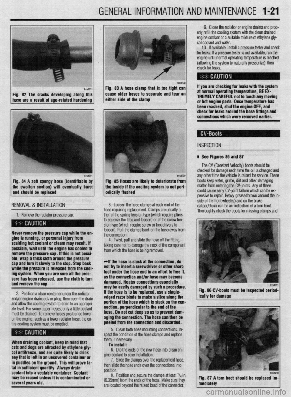
IWSIZXJ FM. 83 A hose clamn that is taa tiaht can
Fig. 82 The cracks developing along this
hose are a result of age-related hardening caise older hoses td separate and ‘iear on
either side of the clamp
lCCS1221 Fig. 84 A soft spongy hose (identifiable by
1 the swollen section) will eventually burst
and should be replaced
IEMOVAL &,INSTALLATION '
1. Remove the radiator pressure cap. her of the sorina tension tvoe (which reouire oliers
3 squeeze the 6bs and loosenj or of the’screw ten-
ion type (which require screw or hex drivers to
oosen). Pull the clamps back on the hose away from
he connection. Never remove the pressure cap while the en-
gine is running, or personal injury from
scalding hot coolant or steam may result. If
possible, wait until the engine has cooled to
remove the pressure cap. If this is not possi-
ble, wrap a thick cloth around the pressure
cap and turn it slowly to the stop. Step back
while the pressure is released from the cool-
ing system. When you are sure all the pres-
sure has been released, use the cloth to turn
and remove the cao.
2. Position a clean container under the radiator
and/or engine draincock or plug, then open the drain
and allow the cooling system to drain to an appropri-
ate level. For some upper hoses, only a little coolant
must be drained. To remove hoses positioned lower
on the engine, such as a lower radiator hose, the en-
tire cooling system must be emptied.
When draining coolant, keep in mind that
cats and dogs are attracted by ethylene gly-
col antifreeze, and are quite likely to drink
any that is left in an uncovered container or
in puddles on the ground. This will prove fa-
tal in sufficient quantity. Always drain
coolant into a sealable container. Coolant
may be reused unless it is contaminated or
several years old. 9. Close the radiator or engine drains and prop-
erly refill the cooling system with the clean drained
engine coolant or a suitable mixture of ethylene gly-
cot coolant and water.
10. If available, install a pressure tester and check
for leaks. If a pressure tester is not available, run the
engine until normal operating temperature is reached
(allowing the system to naturally pressurize), then
check for leaks.
If you are checking for leaks with the system
at normal operating temperature, BE EX-
TREMELY CAREFUL not to touch any moving
or hot engine parts. Once temperature has
been reached. shut the enaine OFF. and
Fig. 85 Hoses are likely to deteriorate from
the inside if the cooling system is not peri-
odically flushed check for leaks around the-hose fittings and
connections which were removed earlier.
INSPECTION
b See Figures 88 and 87
The CV (Constant Velocity) boots should be
checked for damage each time the oil is changed and
any other time the vehicle is raised for service. These
boots keep water, grime, dirt and other damaging
matter from entering the CV-joints. Any of these
could cause early CV-joint failure which can be ex-
pensive to repair. Heavy grease thrown around the in-
side of the front wheel(s) and on the brake
caliper/drum can be an indication of a torn boot.
Thorouahlv check the boots for missina clamos and 3. Loosen the hose clamps at each end of the
rose requiring replacement. Clamps are usually ei-
4. Twist, pull and slide the hose off the fitting,
sking care not to damage the neck of the component
rom which the hose is being removed.
*If the hose is stuck at the connection, do
lot try to insert a screwdriver or other sharp
ool under the hose end in an eff art to free it,
IS the connection and/or hose may become
lamaged. Heater connections especially
nay be easily damaged by such a procedure.
f the hose is to be replaced, use a single-
!dged razor blade to make a slice along the
lortion of the hose which is stuck on the con-
section, perpendicular to the end of the
lose. 00 not cut deep so as to prevent dam-
aging the connection. The hose can then be
keeled from the connection and discarded. Fig. 86 CV-boots must be inspected period-
5.. Clean both hose mounting connections. In-
,pect the condition of the hose clamps and replace
hem, if necessary.
To install:
6. Dip the ends of the new hose into clean en-
fine coolant to ease installation.
7. Slide the clamps over the replacement hose,
hen slide the hose ends over the connections into
rosition.
8. Position and secure the clamps at least l/d in.
6.35mm) from the ends of the hose. Make sure they
Ire located beyond the raised bead of the connector.
Page 30 of 408
GENERALINFORMATIONAND MAlNTENANdE 1-31
When rotating “unidirectional tires,” make sure
that they always roll in the same direction. This
means that a tire used on the left side of the vehicle
must not be switched to the right side and vice-versa.
Such tires should only be rotated front-to-rear or
rear-to-front, while always remaining on the same
side of the vehicle. These tires are marked on the
sidewall as to the direction of rotation; observe the
marks when reinstalling the tire(s).
Some styled or “mag” wheels may have different
offsets front to rear. In these cases, the rear wheels
must not be used up front and vice-versa. Further-
more, if these wheels are equipped with unidirectional
tires, they cannot be rotated unless the tire is re-
mounted for the proper direction of rotation.
*The compact or space-saver spare is
strictly for emergency use. it must never be
included in the tire rotation or placed on the
vehicle for everyday use. check the installed tire for any sign of interference
with the body or suspension while the vehicle is stop-
ping, turning sharply or heavily loaded.
Snow Tires
Good radial tires can produce a big advantage in
slippery weather, but in snow, a street radial tire does
not have sufficient tread to provide traction and con-
trol. The small grooves of a street tire quickly pack
with snow and the tire behaves like a billiard ball on a
marble floor, The more open, chunky tread of a snow
tire will self-clean as the tire turns, providing much
better grip on snowy surfaces.
To satisfy municipalities requiring snow tires dur-
ing weather emergencies, most snow tires carry either
an M + S designation after the tire size stamped on
the sidewall, or the designation “all-season.” In gen-
eral, no change in tire size is necessary when buying
snow tires.
Most manufacturers stronqlv recommend the use styled wheels, see if inexpensive steel
wheels are available, Although the look of
the vehicle will change, the expensive
wheels will be protected from salt, curb hits
and pothole damage.
TIRESTORAGE
If they are mounted on wheels, store the tires at
proper inflation pressure. All tires should be kept in a
cool, dry place. If they are stored in the garage or
basement, do not let them stand on a concrete floor;
set them on strips of wood, a mat or a large stack of
newspaper. Keeping them away from direct moisture
is of paramount importance. Tires should not be
stored upright, but in a flat position.
INFLATION & INSPECTION
b See Figures 140 thru 147
TIRE DESIGN
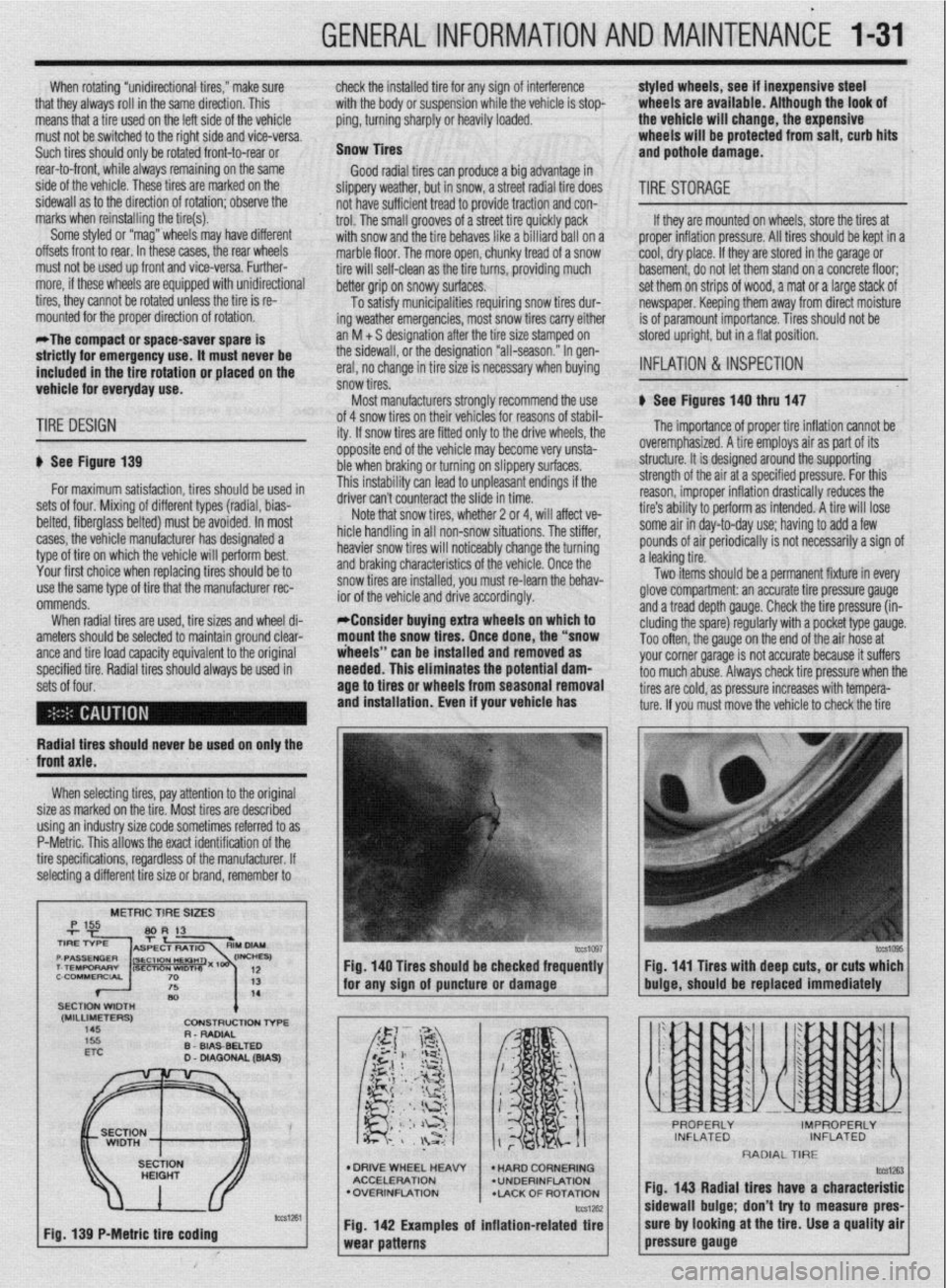
p See Figure 139
for maximum satisfaction, tires should be used in
sets of four. Mixing of different types (radial, bias-
belted, fiberglass belted) must be avoided. In most
cases, the vehicle manufacturer has designated a
type of tire on which the vehicle will perform best.
Your first choice when replacing tires should be to
use the same type of tire that the manufacturer rec-
ommends.
When radial tires are used, tire sizes and wheel di-
ameters should be selected to maintain ground clear-
ante and tire load caoacitv eauivalent to the oriainal
specified tire. Radial tiresshould always be used in
sets of four. of 4 snow tires on their
lehicies for reasons of stabil-
ity. If snow tires are fitter
1 only to the drive wheels, the
opposite end of the vehil cle may become very unsta-
ble when braking or turn
ring on slippery surfaces.
This instability can lead to unpleasant endings if the
A*:,,“- r-..l, ^_.. ..& ^_^^, &I.
UIIVU MII I LUUII~~MLL iue slide in time.
Note that snow tires, whether 2 or 4, will affect ve-
hicle handling in all non-snow situations. The stiffer,
heavier snow tires will noticeably change the turning
and braking characteristics of the vehicle. Once the
snow tires are installed, you must re-learn the behav-
ior of the vehicle and drive accordingly.
*Consider buying extra wheels on which to
mount the snow tires. Once done, the “snow
iheeis” can be installed and removed as
needed. This eliminates the potential
dam- age to tires or wheels from seasonal removal
and installation. Even if your vehicle has
lb The importance of proper tire inflation cannot be
overemphasized. A tire employs air as part of its
structure. It is designed around the supporting
strength of the air at a specified pressure. For this
reason, improper inflation drastically reduces the
tire’s ability to perform as intended. A tire will lose
some air in day-to-day use; having to add a few
pounds of air periodically is not necessarily a sign of
a leaking tire.
Two items should be a permanent fixture in every
glove compartment: an accurate tire pressure gauge
and a tread depth gauge. Check the tire pressure (in-
eluding the spare) regularly with a pocket type gauge.
Too often, the gauge on the end of the air hose at
vnr rr corner narane is not accurate because it suffers
~rs check tire oressure when the
Radial tires should never be used on only the
XI I._.
‘-’ --“‘“’ J s too much abuse. Alwa!
tires are cold, as pressure increases with tempera-
ture. If you must move the vehicle to check the tire
front axle.
When selecting tires, pay attention to the original
size as marked on the tire. Most tires are described
using an industry size code sometimes referred to as
P-Metric. This allows the exact identification of the
tire specifications, regardless of the manufacturer. If
selecting a different tire size or brand, remember to
METRIC TIRE SIZES
(MILLIMETERS)
145 CDNStRUCtlDN l-6-E
R - RADIAL
D
WA9
Fig. 139 P-Metric tire coding Fig. 140 Tires should be checked frequently
I I Fig. 141 Tires with deep cuts, or cuts which
for any sion of auncture or damaoe
buioe, should be replaced immediately
l DRIVE WHEEL HEAW
ACCELERATION
l OVERINFLATION
*LACK OF ROTATION
Fig. 142 Examples of inflation-related tire
RADIAL TIRE
fig. 143 Radial tires have a characteristic
sidewall bulge; don’t try to measure pres-
sure by looking at the tire. Use a quality air
pressure gauge
Page 31 of 408
.
1-32 GENERALINFORMATIONAND MAINTENANCE
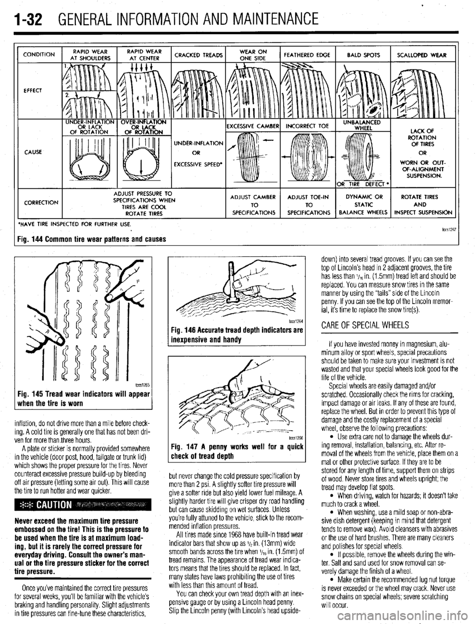
CONDITION
EFFECT
CAUSE
CORRECTION UNDER-INFLATION
EXCESSIVE SPEED’ WORN OR OUT-
OF-ALIGNMENT
ADJUST PRESSURE TO
SPECIFICATIONS WHEN
TIRES ARE COOL
ROTATE TIRES
/ BALANCE WHEELS INSPECT SUSPENSION
HAVE TIRE INSPECTED FOR FURTHER USE.
lCCSi267 ig. 144 Common tire wear patterns and causes
1~~~1265 Fig. 145 Tread wear indicators will appear
when the tire is worn
inflation, do not drive more than a mile before check-
ing. A cold tire is generally one that has not been dri-
ven for more than three hours.
A plate or sticker is normally provided somewhere
in the vehicle (door post, hood, tailgate or trunk lid)
which shows the proper pressure for the tires. Never
counteract excessive pressure build-up by bleeding
off air pressure (letting some air out). This will cause
the tire to run hotter and wear quicker.
Never exceed the maximum tire pressure
embossed on the tire! This is the pressure to
be used when the tire is at maximum load-
ing, but it is rarely the correct pressure for
everyday driving. Consult the owner’s man-
ual or the tire pressure sticker for the correct
tire pressure.
Once you’ve maintained the correct tire pressures
for several weeks, you’ll be familiar with the vehicle’s
braking and handling personality. Slight adjustments
in tire pressures can fine-tune these characteristics,
1~~~1264 Fig. 146 Accurate tread depth indicators are
inexuensive and handv
Fig. 147 A penny works well for a quick
check of tread death
but never change the cold pressure specification by
more than 2 psi. A slightly softer tire pressure will
give a softer ride but also yield lower fuel mileage. A
slightly harder tire will give crisper dry road handling
but can cause skidding on wet surfaces. Unless
you’re fully attuned to the vehicle, stick to the recom-
mended inflation pressures.
All tires made since 1968 have built-in tread wear
indicator bars that show up as j/2 in. (13mm) wide
smooth bands across the bre when V,~ in. (1.5mm) of
tread remains. The appearance of tread wear indica-
tors means that the tires should be replaced. In fact,
many states have laws prohibiting the use of tires
with less than this amount of tread.
You can check your own tread depth with an inex-
pensive gauge or by using a Lincoln head penny.
Shp the Lrncoln penny (with Lincoln’s head upside- down) into several tread grooves. If you can see the
top of Lincoln’s head in 2 adjacent grooves, the tire
has less than V,~ in. (1.5mm) tread left and should be
replaced. You can measure snow tires in the same
manner by using the “tails” side of the Lincoln
penny. If you can see the top of the Lincoln memor-
ial, its time to replace the snow tire(s).
CAREOFSPECIALWHEELS
If you have invested money in magnesium, alu-
minum alloy or sport wheels, special precautions
should be taken to make sure your investment is not
wasted and that your special wheels look good for the
life of the vehicle.
Special wheels are easily damaged and/or
scratched. Occasionally check the rims for cracking,
impact damage or air leaks. If any of these are found,
replace the wheel. But in order to prevent this type of
damage and the costly replacement of a special
wheel, observe the following precautions:
l Use extra care not to damage the wheels dur-
ing removal, installation, balancing, etc. After re-
moval of the wheels from the vehicle, place them on a
mat or other protective surface. If they are to be
stored for any length of time, support them on strips
of wood. Never store tires and wheels upright; the
tread may develop flat spots.
l When driving, watch for hazards; it doesn’t take
much to crack a wheel.
l When washing, use a mild soap or non-abra-
sive dish detergent (keeping in mind that detergent
tends to remove wax). Avoid cleansers with abrasives
or the use of hard brushes. There are many cleaners
and polishes for special wheels.
l If possrble, remove the wheels during the win-
ter. Salt and sand used for snow removal can se-
verely damage the finish of a wheel.
l Make certain the recommended lug nut torque
is never exceeded or the wheel may crack. Never use
snow chains on special wheels; severe scratching
will occur.
Page 37 of 408

t
1-38 GENERALINFORMATIONAND MAINTENANCE
11 I Add the recommended automatic transaxle
fluid to the transaxle through the dipstick tube. You
will need a long necked funnel, or a funnel and tube
to do this. A quick check of the capacities chart later
in this Section will reveal the capacity of the transaxle
in your vehicle. On a first fill after removing the pan
and filter, this number should be cut into a ‘hand
checked on the dipstick before refilling.
12. With the transaxle in P, put on the parking
brake, block the front wheels, start the engine and let
it idle. DO NOT RACE THE ENGINE. DO NOT MOVE
THE LEVER THROUGH ITS RANGES.
13. With the lever in Park, check the fluid level. If
it’s OK, take the car out for a short drive, park on a
level surface, and check the level again, as outlined
earlier in this section. Add more fluid if necessary. Be
careful not to overfill, which will cause foaming and
w fluid loss. n of the transfer case filler
3. Remove the filler and the drain plug and allow
the oil to drain into the drain pan.
4. After the fluid has drained completely, install
the drain plug and tighten to 24 ft. Ibs. (32 Nm).
5. Refill the transfer case to the proper level with
Fig. 184 . . .
the transaxle case before in-
stalling the gasket
and pan onto the case FLUID RECOMMENDATIONS Hypoid gear oil SAE 75W-85W/75W-9OW conform-
ing to API specifications GL-4 or higher. The oil level
-‘-,*I’ -nnnh +‘* “%om edge of the oil filler hole.
nxfer raw filler nlm and tinhtm When adding fluid or refilling the transfer case,
use Hypoid gear oil SAE 75W-85W or 75W-9OW
conforming to API specifications 61-4 or higher.
LEVELCHECK 6. Install the tra .._._. ____ .._. T.-J _.._ .lJ . .._..
to 24 ft. lbs. (32 Nm).
7. Carefully lower the vehicle.
u See Figure 185
, 1 FLUID RECOMMENDATIONS
delivery service, the fluid should be changed accord-
ing to the severe service schedule.
The fluid must be hot before it is drained; a 20 u See Figure 187
Since fluid viscosity range may
vary depending on
specific temperature range of operation, please refer
~~
tne transaxle case.
You’ll be very sorry later if you do. bottom edge of the transfer case filler 1 1 Fig. 187 Rear axle lubricant application I
*If the drained fluld is discolored (brown or
1 plug hole chart black), thick, or pmmll~ hmmt nnrinmm I transaxle trouble .llln3llU ““III., url,““P s, probably due to overheat-
,r..rr,rA “#.a.- rrdr
trig, should be susp~~lr;u. lvUl vLlr J
transaxle should be inspected by a reliable
transaxle specialist to determine the prob-
lem.
5. Remove the pan and gasket.
6. Clean the pan with solvent and allow it to air
dry. If you use a rag to wipe out the pan, you risk
leaving bits of lint behind, which will clog the dinky
hydraulic passages in the bansaxle.
7. Remove the filter retaining bolts and remove
the filter from the valve bodv. lnsoect each component for leaking. Check the oil
he filler plug. If the oil is contami-
ry to replace it with new oil.
if% nn IPVPI z11rf2r~
level by removing t
nated, it is necessa
1. Park the vehi,., -.. ,-.“, __. ,“-_.
2. Remove the filler plug and make sure the oil
level reaches the lower edge of the filler plug hole.
3. Check to be sure that the oil is not noticeably
dirty and that it has the proper viscosity.
4. If necessary, add oil through the filler hole until
is runs out of the hole. to the accompanying chart for the proper fluid for
your vehicle.
LEVEL CHECK
1. Make sure the vehicle is parked on level
ground.
2. Remove the oil fill plug to check the oil level.
3. The oil level is sufficient if it reaches the lower
portion of the filler plug hole. If the fluid is low, add
as required through the filler plug.
To install: .
8. Install a new filter, then install the retaining
bolts and tighten them to 5 ft. Ibs. (7 Nm).
9. Position the gasket on the pan, then install
the pan. Tighten the bolts evenly and in rotation to
8-9ft. Ibs. (10-12 Nm.). Do not overtighten.
IO. Lower the vehicle. DRAIN & REFILL
I8 DRAIN & REFILL
u See Figure 188 ) See Figure- 14
1. Raise and safely support the vehicle, for access
to the transfer case.
2. Place a suitable drain pan under the transfer
case fluid drain plug. 1. Position the vehicle on a flat surface or raise
and safely support the vehicle in a level position.
2. Place a suitable drain pan under the rear axle.
Page 46 of 408
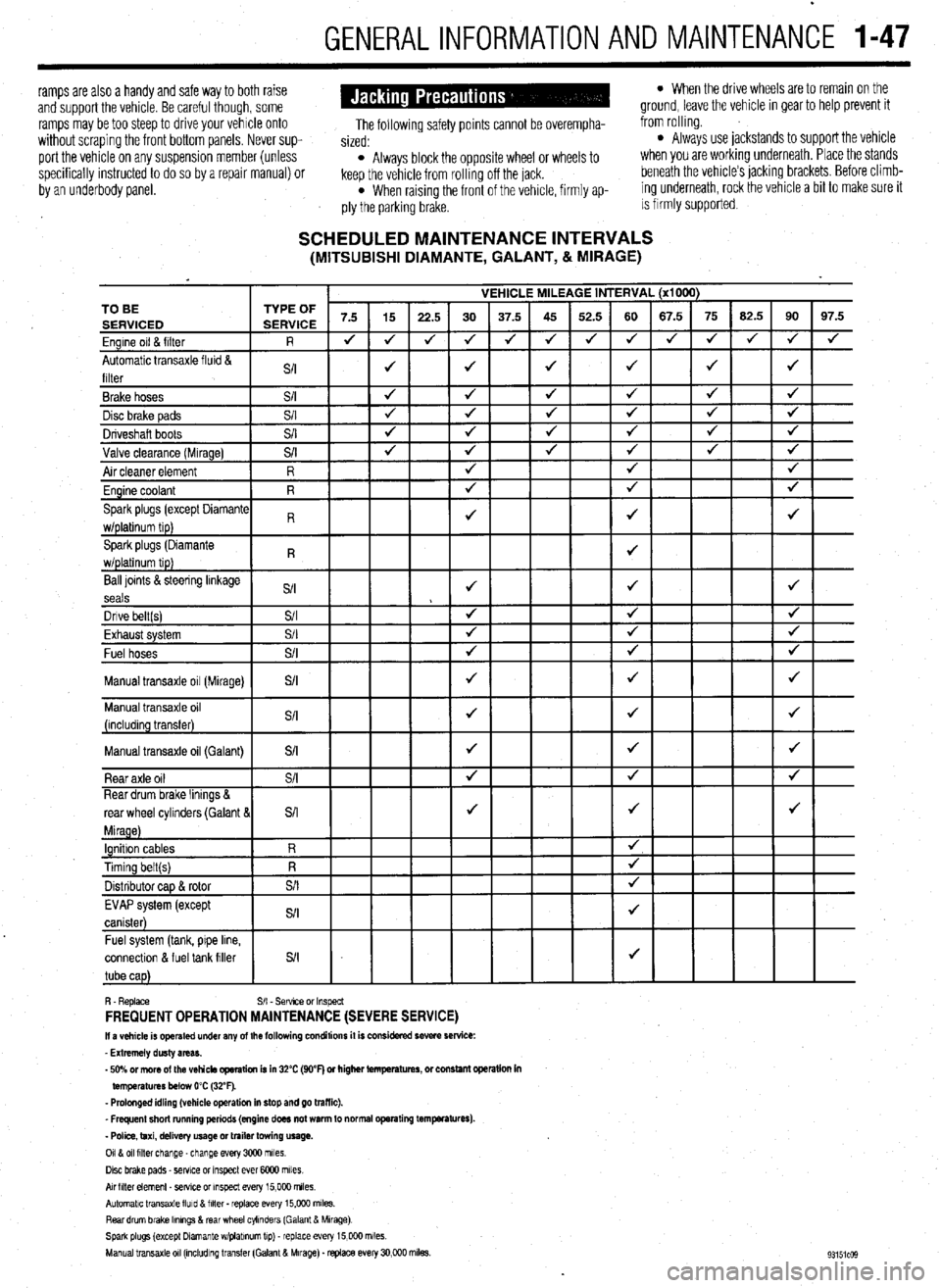
GENERAL INFORMATION AND MAINTENANCE 1-47
ramps are also a handy and safe way to both raise l When the drive wheels are to remain on the
and support the vehicle. Be careful though, some ground, leave the vehicle in gear to help prevent it
ramps may be too steep to drive your vehicle onto
The following safety points cannot be overempha- from rolling.
without scraping the front bottom panels. Never sup-
sized:
l Always use jackstands to support the vehicle
port the vehicle on any suspension member (unless l Always block the opposite wheel or wheels to when you are working underneath. Place the stands
specifically instructed to do so by a repair manual) or
keep the vehicle from rolling off the jack. beneath the vehrcle’s jacking brackets Before climb-
by an underbody panel.
l When raising the front of the vehicle, firmly ap- ing underneath, rock the vehicle a bit to make sure it
ply the parking brake. is firmly supported.
SCHEDULED MAINTENANCE INTERVALS (MITSUBISHI DIAMANTE, GALANT, & MIRAGE)
VEHICLE MILEAGE INTERVAL (x1000)
7.5 15
22.5 30 37.5 45 52.5 60 67.5 75 62.5 90 97.5
J J
J 4 J J 4 4 4 J J
J 4
4
J J J J 4 TO BE
Ball loints &steering linkage
S/I J J J
seals
Dnve belt(s) S/I 4 4 J
Fvha,,rt cvctom $/I
J J J LmI,..“w. “,YL”,‘. Fuel hoses
+
Manual transaxle oil (Galant)
connectlon & fuel tank filler
R. Replace S/I - Sefwce or Inspect FREQUENT OPERATION MAINTENANCE (SEVERE SERVICE) II a vehicle is operated under any of the following conditions it is considered severe service:
- Extremely dusty areas.
- 50% or more of the vehicle operation is in 32% (WF) or higher temperatures, or constant opsralion in
temperatures below 0% (32°F).
- Prolonged idling (vehicle operation in stop and go traffic).
_ Frequent short running periods (engine does not warm to normal operating temfwatures).
- Police, taxi, delivery usage or trailer towing usage.
0118 011 filter change-change every 3CQO miles.
Disc brake pads - sewce or Inspect ever 6COO miles
AN hlter element _ setwe or inspect every 15,000 miles.
Automatic transaxle lluld 8 filter . replace every 15,COO m&s.
Rear drum brake Ikmngs & rear wheel cylinders (Galant & Mirage)
Spark plugs (except Dlamante wlplabnum tip) - replace every 15,COO miles.
Manual transaxle 011 (mcludlng transfer (Galant & Mirage). replace every 30,000 miles.
Page 213 of 408
640 CHASSIS ELECTRICAL
careful not to allow anything to come in contact with
the air bag unit.
16. Remove the glove box lamp assembly.
17. Remove the remaining instrument panel
mounting screws and remove the instrument panel
from the vehicle.
18. Remove the left side foot shower ductwork,
lap cooler duct and center duct.
19. Remove the front and center reinforcements
and center stay assembly.
20. Remove the air distribution duct assembly.
21. Detach all connectors from heater-box-
mounted items.
22. Remove the heater box mounting screws and
nut, then remove the unit from the vehicle.
23. Disassemble on a workbench. Remove the
heater core from the heater case.
To install:
24. Thoroughly clean and dry the inside of the
case and install the heater core and all related parts.
25. Install the heater unit to the vehicle and install
the mounting screws and nut. Be sure the evaporator
case and heater case are fitted together properly. At-
tach all connectors to heater-box-mounted items.
26. Install the air distribution duct assembly. In-
stall the front and center reinforcements and center
stay assembly.
27. Install the center duct, lap cooler duct and left
side foot shower duct.
28. Install the instrument panel and mounting
screws.
29. Install the glove box lamp assembly.
30. Secure the steering column and attach all
steering column connectors.
31. Install the speedometer cable adapter to the
instrument panel.
32. Install the instrument cluster and the instru-
ment cluster bezel.
33. Install the speakers to the top of the instru-
ment panel.
34. Install the cup holder.
35. Install the climate control system control
head.
36. Install the stereo entertainment system and
bezel.
37. Install the screw below the glove box assem-
bly, and the entire glove box unit.
38. Install the steering column covers.
39. Install the knee protector support bracket, the
protector and the decorative plugs.
40. Install the console and the ashtray. 41. Install the right side foot shower duct.
42. Install the passenger side undercover.
43. Connect the heater hoses to the core tubes.
44. Fill the cooling system.
45. Connect the negative battery cable and check
the entire climate control system for proper operation
and leaks.
Galant
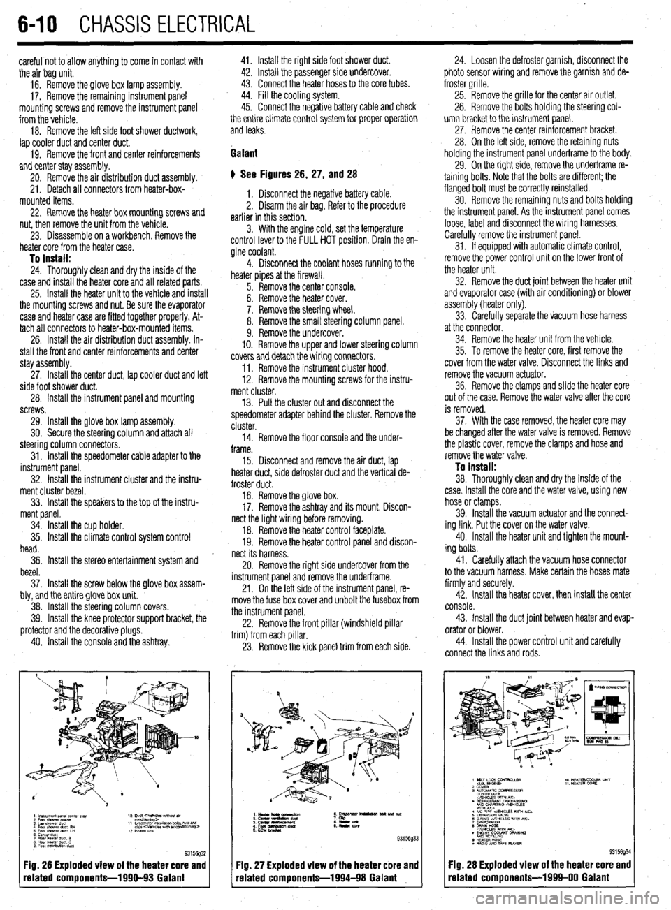
# See Figures 26, 27, and 28
1. Disconnect the negative battery cable.
2. Disarm the air bag. Refer to the procedure
earlier in this section.
3. With the engine cold, set the temperature
control lever to the FULL HOT position. Drain the en-
gine coolant.
4. Disconnect the coolant hoses running to the
heater pipes at the firewall.
5. Remove the center console.
6. Remove the heater cover.
7. Remove the steering wheel.
8. Remove the small steering column panel.
9. Remove the undercover.
10. Remove the upper and lower steering column
covers and detach the wiring connectors.
11. Remove the instrument cluster hood.
12. Remove the mounting screws for the instru-
ment cluster.
13. Pull the cluster out and disconnect the
speedometer adapter behind the cluster. Remove the
cluster.
14. Remove the floor console and the under-
frame.
15. Disconnect and remove the air duct, lap
heater duct, side defroster duct and the vertical de-
froster duct.
16. Remove the glove box.
17. Remove the ashtray and its mount. Discon-
nect the light wiring before removing.
18. Remove the heater control faceplate.
19. Remove the heater control panel and discon-
nect its harness.
20. Remove the right side undercover from the
instrument panel and remove the underframe.
21. On the left side of the instrument panel, re-
move the fuse box cover and unbolt the fusebox from
the instrument panel.
22. Remove the front pillar (windshield pillar
trim) from each pillar.
23. Remove the kick panel trim from each side.
Fig. 26 Exploded view of the heater core and
related components-1990-93 Galant
:IQ. 27 Exploded view of the heater core and
-elated components-1994-98 Galant 24. Loosen the defroster garnish, disconnect the
photo sensor wiring and remove the garnish and de-
froster grille.
25. Remove the grille for the center air outlet.
26. Remove the bolts holding the steering col-
umn bracket to the instrument panel.
27, Remove the center reinforcement bracket.
28. On the left side, remove the retaining nuts
holding the instrument panel underframe to the body.
29. On the right side, remove the underframe re-
taining bolts. Note that the bolts are different; the
flanged bolt must be correctly reinstalled.
30. Remove the remaining nuts and bolts holding
the instrument panel. As the instrument panel comes
loose, label and disconnect the wiring harnesses.
Carefully remove the instrument panel.
31. If equipped with automatic climate control,
remove the power control unit on the lower front of
the heater unit.
32. Remove the duct joint between the heater unit
and evaporator case (with air conditioning) or blower
assembly (heater only).
33. Carefully separate the vacuum hose harness
at the connector.
34. Remove the heater unit from the vehicle.
35. To remove the heater core, first remove the
cover from the water valve. Disconnect the links and
remove the vacuum actuator.
36. Remove the clamps and slide the heater core
out of the case. Remove the water valve after the core
is removed.
37. With the case removed, the heater core may
be changed after the water valve is removed. Remove
the plastic cover, remove the clamps and hose and
remove the water valve.
To install:
38. Thoroughly clean and dry the inside of the
case. Install the core and the water valve, using new
hose or clamps.
39. Install the vacuum actuator and the connect-
ing link. Put the cover on the water valve.
40. Install the heater unit and tighten the mount-
ing bolts.
41. Carefully attach the vacuum hose connector
to the vacuum harness. Make certain the hoses mate
firmly and securely.
42. Install the heater cover, then install the center
console.
43. Install the duct joint between heater and evap-
orator or blower.
44. Install the power control unit and carefully
connect the links and rods.
Fig. 28 Exploded view of the heater core and
related components-1999-00 Galant
Page 281 of 408
7-2 'DRIVETRAIN
Because of the way an internal combustron engine
breathes, it can produce torque, or twisting force,
only within a narrow speed range. Most modern,
overhead valve pushrod engines must turn at about
2500 rpm to produce their peak torque By 4500 rpm
they are producrng so lrttle torque that contrnued in-
creases in engine speed produce no power increases.
The torque peak on overhead camshaft engines IS
generally much higher, but much narrower.
The manual transaxle and clutch are employed to
vary the relationship between engine speed and the
speed of the wheels so that adequate engine power can
be produced under all crrcumstances. The clutch al-
lows engine torque to be applied to the transaxle input
shaft gradually, due to mechanical slippage. Conse-
quently, the vehicle may be started smoothly from a
full stop The transaxle changes the ratio between the
rotating speeds of the engine and the wheels by the
use of gears. The gear ratios allow full engine power to
be applied to the wheels during acceleration at low
speeds and at highway/passing speeds.
In a front wheel drive transaxle, power is usually
transmitted from the input shaft to a mainshaft or out-
put shaft located slightly beneath and to the side of
the input shaft. The gears of the mainshaft mesh with
gears on the input shaft, allowing power to be carried
from one to the other. All forward gears are in con-
stant mesh and are free from rotating with the shaft
unless the synchronizer and clutch IS engaged. Shaft-
ing from one gear to the next causes one of the gears
to be freed from rotating with the shaft and locks an-
other to it. Gears are locked and unlocked by internal
dog clutches which slide between the center of the
gear and the shaft. The forward gears employ syn-
chronizers; friction members which smoothly bring
gear and shaft to the same speed before the toothed
dog clutches are engaged.
SHIFT LINKAGE
1. Disconnect the shift linkage from the transaxle.
2. On the transaxle, put select lever in N and
move the shift lever in
4th gear. Depress the clutch,
if necessary, to shift.
3. Move the shift lever in the vehicle to the
4th gear position until it contacts the stop.
4. Turn the adjuster turnbuckle so the shift cable
eye aligns with the eye in the gear shift lever. When
installing the cable eye, make sure the flange side of
the plastic bushing at the shift cable end is on the
cotter pin side.
5 The cables should be adjusted so the clear-
ance between the shift lever and the 2 stoppers are
equal when the shift lever IS moved to 3rd and 4th
gear. Move the shift lever to each positron and check i
that the shifting is smooth
REMOVAL &INSTALLATION
1, Disconnect the negative battery cable 2. Remove any components necessary to access
the back-up light switch.
3. Unplug the back-up light switch connector.
4. Remove the switch from the case using the ap-
propriate size socket and drive tool.
To install: 5. Install the switch and tighten it to 22-25 ft. Ibs.
(30-35 Nm).
6. Attach the back-up light switch connector
7. Install any components removed to access the
back-up light switch
8. Connect the negative battery cable.
REMOVAL & INSTALLATION
Mirage
*If the vehicle is going to be roiled while the
halfshafts are out of the vehicle, obtain 2 outer
CV-joints or proper equivalent tools and install
to the hubs. If the vehicle is rolled without the
proper torque applied to the front wheel bear-
ings, the bearings will no longer be usable.
*The suspension components should not be
tightened until the vehicles weight is resting
on the ground.
1. Remove the battery and battery tray.
2. Remove the air cleaner assembly and vacuum
hoses.
3. Note the locations and disconnect the shifter
cables.
4. If equipped with 1.61 engine, remove the ten-
sion rod.
5. Detach the backup lamp switch connector,
speedometer cable connection and remove the starter
motor.
6. Raise the vehicle and support safely.
7. Remove the front wheels and the inner wheel
panels.
8. Remove the undercover and splash pan.
9. Drain the transaxle oil into a suitable con-
tainer
10. Support the engine and remove the cross-
member.
11. Remove the upper transaxle mounting bolt
and bracket.
12 Disconnect the stabilizer bar, tie rod ends and
the lower ball joint connections.
13 Remove the clutch release cylinder and clutch
oil line bracket. Do not disconnect the fluid lines and
secure the slave cylinder with wire.
14 Disconnect the clutch cable, if equipped with
cable controlled clutch system.
15. Remove the halfshafts by inserting a prybar
between the transaxle case and the driveshaft and
prying the shaft from the transaxle. Do not pull on the
driveshaft Doing so damages the inboard joint. Do
not insert the prybar so far the oil seal in the case is
damaged.
*It is not necessary to disconnect the half-
shafts from the steering knuckle. Remove the
shaft with the hub and knuckle as an assem-
bly. Tie the shafts aside. Note the circle clip
on the end of the inboard shafts should not
be reused.
16. Remove the bellhousing lower cover.
17 Remove the transaxle to engine bolts and
lower the transaxle from the vehrcle.
To install:
*When installing the transaxle, be sure to
align the splines of the transaxle with the
clutch disc.
18 Install the transaxle to the engine and install
the mounting bolts. Tighten the bolts to 31-40 ft. Ibs.
(43-55 Nm) on 1990-92 models and 35 ft. Ibs. (48
Nm) on 1993-00 models.
19 Install the bellhousing cover.
*When installing the halfshafts, use new
circlips on the axle ends. Care must be taken
to ensure that the oil seal lip of the transaxle
is not damaged by the serrated part of the
driveshaft.
20. Install and fully seat the halfshafts into the
transaxle.
21. Install the slave cylinder.
22. Connect the ball joints, tie rod ends and the
stabilizer bar connections.
23. Install the upper transaxle mounting bracket
and bolt.
24. Install the crossmember.
25. Install the undercover.
26. Install the upper transaxle-to-engine mount-
ing bolts, Tighten the bolts to 31-40 ft. Ibs. (43-55
Nm) on 199C-92 models and 35 ff. Ibs. (48 Nm) on
1993-00 models.
27. Install the starter motor.
28 Connect the backup light switch connector
and speedometer cable.
29 Connect and adjust the shifter cables.
30 Install the air cleaner assembly.
31. Install the front wheels.
32 Make sure the vehicle is level when refilling
the transaxle Use Hypoid gear oil or equivalent, GL-
4 or higher.
33. Connect the negative battery cable and check
the transaxle for proper operation. Make sure the re-
verse lights operate when in reverse.
Galant
1999-93 MODELS
rlf the vehicle is going to be rolled on its
wheels while the halfshafts are out of the ve-
hicle, obtain two outer CV-joints or proper
equivalent tools and install to the hubs. If the
vehicle is rolled without the proper torque
applied to the front wheel bearings, the bear-
ings will no longer be usable.
1. Remove the battery and the air intake hoses.
2. If equipped with Active-ECS, unplug the
compressor wiring.
3. Remove the auto-cruise actuator and under-
hood bracket, located on the passenger side inner
fender well.
4. Drain the transaxle and transfer case fluid, if
equipped, into a suitable waste container.
5. Remove the retainer bolt and pull the
speedometer cable from the transaxle assembly.
6. Remove the cotter pin securing the select and
shift cables and remove the cable ends from the
transaxle.
Page 289 of 408
7-10 DRIVETRAIN
The automatic transaxle allows engine torque and
power to be transmitted to the front wheels within a
narrow range of engine operating speeds. It will allow
the engine to turn fast enough to produce plenty of
power and torque at very low speeds, while keeping it
at a sensible rpm at high vehicle speeds (and it does
this job without driver assistance). The transaxle uses
a light fluid as the medium for the transmission of
power. This fluid also works in ths operation of vari-
ous hydraulic control circuits and as a lubricant. Be-
cause the transaxle fluid performs all of these func-
tions, trouble within the unit can easily travel from one
part to another For this reason, and because of the
complexity and unusual operating principles of the
transaxle, a very sound understanding of the basic
principles of operation will simplify troubleshooting
REMOVAL &INSTALLATION
Pan removal, fluid and filter
in Section 1 of this manual changes are covered
REMOVAL &INSTALLATION
1990-97 Mirage and 1990-93 Galant
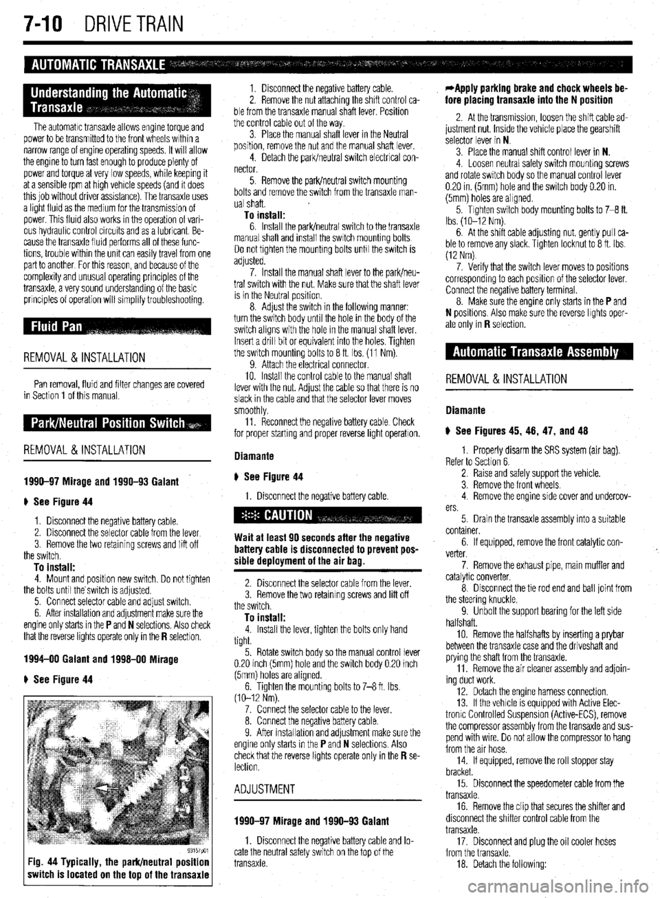
# See Figure 44
1. Disconnect the negative battery cable.
2. Disconnect the selector cable from the lever
3. Remove the two retaining screws and lift off
the switch.
To install: 4. Mount and position new switch. Do not tighten
the bolts until the switch is adjusted.
5. Connect selector cable and adjust switch.
6. After installation and adjustment make sure the
engine only starts in the
P and N selections. Also check
that the reverse lights operate only in the R selectlon.
1994-00 Galant and 1998-00 Mirage
e See Figure 44
93157pm Fig. 44 Typically, the park/neutral position
switch is located on the top of the transaxle
1. Disconnect the negative battery cable.
2. Remove the nut attaching the shift control ca-
ble from the transaxle manual shaft lever. Position
the control cable out of the way.
3. Place the manual shaft lever in the Neutral
position, remove the nut and the manual shaft lever.
4. Detach the park/neutral switch electrical con-
nector.
5. Remove the park/neutral switch mounting
bolts and remove the switch from the transaxle man-
ual shaft.
To install: 6. Install the park/neutral switch to the transaxle
manual shaft and install the switch mounting bolts
Do not tighten the mounting bolts unh the switch is
adjusted.
7. Install the manual shaft lever to the park/neu-
tral switch with the nut. Make sure that the shaft lever
is in the Neutral position.
8. Adjust the switch in the following manner:
turn the switch body until the hole in the body of the
switch aligns with the hole in the manual shaft lever.
Insert a drill bit or equivalent into the holes. Tighten
the switch mounting bolts to 8 ft. Ibs. (11 Nm).
9. Attach the electrical connector.
10. Install the control cable to the manual shaft
lever with the nut. Adjust the cable so that there is no
slack in the cable and that the selector lever moves
smoothly
11. Reconnect the negative battery cable Check
for proper starting and proper reverse light operatron.
Diamante
ti See Figure 44
1. Disconnect the negative battery cable.
Wait at least 90 seconds after the negative
battery cable is disconnected to prevent pos-
sible deployment of the air bag.
2. Disconnect the selector cable from the lever.
3. Remove the two retaining screws and lift off
the switch.
To install: 4. Install the lever, tighten the bolts only hand
tight.
5. Rotate switch body so the manual control lever
0.20 inch (5mm) hole and the switch body 0.20 inch
(5mm) holes are aligned.
6. Tighten the mounting bolts to 7-8 ft. Ibs.
(10-12 Nm).
7. Connect the selector cable to the lever.
8. Connect the negative battery cable.
9. After installahon and adjustment make sure the
engine only starts in the
P and N selections. Also
check that the reverse lights operate only in the R se- lection.
ADJUSTMENT
1990-97 Mirage and 1990-93 Galant
1. Disconnect the negative battery cable and lo-
cate the neutral safety switch on the top of the
transaxle.
*Apply parking brake and chock wheels be-
fore placing transaxle into the N position
2. At the transmission, loosen the shift cable ad-
justment nut. Inside the vehicle place the gearshift
selector lever in N
3. Place the manual shift control lever in N.
4. Loosen neutral safety switch mounhng screws
and rotate switch body so the manual control lever
0.20 in. (5mm) hole and the switch body 0.20 in.
(5mm) holes are aligned.
5. Tighten switch body mounting bolts to 7-8 ft.
Ibs. (lo-12 Nm).
6. At the shift cable adjusting nut, gently pull ca-
ble to remove any slack. Tighten locknut to 8 ft. Ibs.
(12 Nm)
7. Verify that the switch lever moves to positions
corresponding to each position of the selector lever.
Connect the negative battery terminal.
8. Make sure the engine only starts in the
P and
N positions. Also make sure the reverse lights oper-
ate only in
R selection.
REMOVAL&INSTALLATION
Diamante
) See Figures 45, 46, 47, and 48
1. Properly disarm the SRS system (air bag).
Refer to Section 6.
2. Raise and safely support the vehicle.
3. Remove the front wheels.
4. Remove the engine side cover and undercov-
ers.
5. Drain the transaxle assembly into a suitable
container.
6. If equipped, remove the front catalytic con-
verter.
7. Remove the exhaust pipe, main muffler and
catalytic converter.
8. Disconnect the tie rod end and ball joint from
the steering knuckle.
9. Unbolt the support bearing for the left side
halfshaft.
10. Remove the halfshafts by inserting a prybar
between the transaxle case and the driveshaft and
prying the shaft from the transaxle.
11. Remove the air cleaner assembly and adjoin-
ing duct work.
12. Detach the engine harness connection.
13. If the vehicle is equipped with Active Elec-
tronlc Controlled Suspension (Active-ECS), remove
the compressor assembly from the transaxle and sus-
pend with wire. Do not allow the compressor to hang
from the air hose.
14. If equipped, remove the roll stopper stay
bracket.
15. Disconnect the speedometer cable from the
transaxle.
16. Remove the clip that secures the shifter and
disconnect the shifter control cable from the
transaxle.
17. Disconnect and plug the oil cooler hoses
from the transaxle.
18. Detach the following:
Page 334 of 408
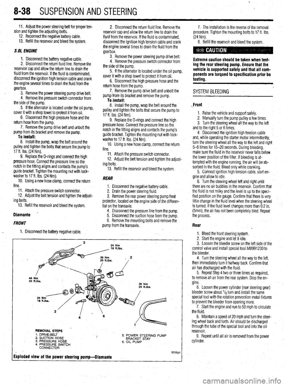
- 8-38 SUSPENSION AND STEERING
11. Adjust the power steering belt for proper ten-
sion and tighten the adjusting bolts.
12. Reconnect the negative battery cable.
13. Refill the reservoir and bleed the system.
3. Of EIJGINE
1. Disconnect the battery negative cable. 2. Disconnect the return fluid line. Remove the
reservoir cap and allow the return line to drain the
fluid from the reservoir. If the fluid is contaminated,
disconnect the ignition high tension cable and crank
the engine several times to drain the fluid from the
gear box.
3. Remove the power steering pump drive belt.
4. Remove the pressure switch connector from
the side of the pump.
5. If the alternator is located under the oil pump,
cover it with a shop towel to protect it from oil.
6. Disconnect the high pressure hose and the
return hose from the pump.
7. Remove the pump drive belt and unbolt the
pump from its bracket and remove the pump.
To install: 8. Install the pump, *rap the belt around the
pulley and tighten the bolts that secure the pump to
17 ft. Ibs. (24 Nm).
9. Replace the O-rings and connect the high
pressure hose. Connect the pressure line so the
notch in the fitting aligns and contacts the pump’s
guide bracket. Tighten the mounting nut with lock-
washer to 17 ft. Ibs. (24 Nm).
IO. Using a new hose clamp, connect the return
line.
11. Attach the pressure switch connector.
12. Adjust the belt tension and tighten the
adjust- ing bolts.
13. Refill the reservoir and bleed the system.
Diamante *
FRONT
. 1. Disconnect the battery negative cable. 2. Disconnect the return fluid line. Remove the
reservoir cap and allow the return line to drain the
fluid from the reservoir. If the fluid is contaminated,
disconnect the ignition high tension cable and crank
the engine several times to drain the fluid from the
gearbox.
3. Remove the power steering pump drive belt.
4. Remove the pressure switch connector from
the side of the pump.
5. If the alternator is located under the oil pump,
cover it with a shop towel to protect it from oil.
6. Disconnect the high pressure hose and the
return hose from the pump.
7. Remove the pump drive belt and unbolt the
pump from its bracket and remove the pump.
To install: 8. Install the pump, wrap the belt around the
pulley and tighten the bolts that secure the pump to
17 ft. Ibs. (24 Nm).
9. Replace the O-rings and connect the high
pressure hose. Connect the pressure line so the
notch in the fitting aligns and contacts the pump’s
guide bracket. Tighten the mounting nut with lock-
washer to 17 ft. Ibs. (24 Nm).
10. Using a new hose clamp, connect the return
line.
Il. Attach the pressure switch connector.
12. Adjust the belt tension and tighten the adjust-
ing bolts.
13. Refill the reservoir and bleed the system.
REAR
1. Disconnect the negative battery cable.
2. Drain the power steering fluid.
3. Remove the rear power steering pump heat
protector, located on the engine side of the differen-
tial on the transaxle.
4. Disconnect the pressure line from the pump.
5. Disconnect the suction hose from the pump.
6. Remove the mounting bolts and remove the
pump from the transaxle.
44
33
REMOVAL STEPS
5. POWER STEERING PUMP
BRACKET STAY
6. OIL PUMP 1. DRIVE-BELT
2. SUCTION HOSE I ’ 3. PRESSURE HOSE
4. PRESSURE SWITCH
CONNECTOR
Exploded view of the power steering pump-Diamante
. 93158ga5
7. The installation is the reverse of the removal
procedure. Tighten the mounting bolts to 17 ft. Ibs.
(24 Nm).
8. Refill the reservoir and bleed the system.
Extreme caution should be taken when test-
ing the rear steering pump. Ensure that the
vehicle is supported safely and that all com-
ponents are torqued to specification prior be
testing.
. SYSTEM BLEEDING
,Front
1. Raise the vehicle and support safely.
2. Manually turn the pump pulley a few times.
3. Turn the steering wheel all the way to the left
and to the right 5 or 6 times.
4. Disconnect the ignition high tension cable
and, while operating the starter motor intermittently,
turn the steering wheel all the way to the letI and right
5-6 times for 15-20 seconds. During bleeding,
make sure the fluid in the reservoir never falls below
the lower position of the filter. If bleeding is at-
tempted with the engine running, the air will be ab-
sorbed in the fluid. Bleed only while cranking.
5. Connect ignition high tension cable, start en-
gine and allow to idle.
6. Turn the steering wheel left and right until
there are no air bubbles in the reservoir. Confirm that
the fluid is not milky and the level is up to the speci-
fied position on the gauge. Confirm that there is very
little change in the fluid level when the steering wheel
is turned. If the fluid level changes more than 0.2 in.
(5mm), the air has not been completely bled. Repeat
the process.
Rear
.
1. Bleed the front steering system.
2. Start the engine and let it idle.
3. Loosen the bleeder screw on the left side of the
control valve and install special tool MB991230 to
the bleeder.
4. Turn the steering wheel all the way to the left,
then immediately turn it halfway back. Confirm that
air has discharged with the fluid.
5. Repeat Step 4 two or three times as required,
to remove all air from the rear system. Stop the en-
gine.
6. Loosen the power cylinder (rear steering gear)
bleeder screw about I/* turn and install the same
special tool with the rotation prevention metal fixtures
to prevent the bleeder from opening more.
7. Start the engine and run to 50 mph to circulate
the fluid.
8. Maintain a speed of 20 mph and turn the steer-
ing wheel back and forth. Air should be discharged ,
through the tube of the special tool and into the oil
reservoir.
9. Repeat until all air is removed from the power
cylinder.