service indicator MITSUBISHI DIAMANTE 1900 Repair Manual
[x] Cancel search | Manufacturer: MITSUBISHI, Model Year: 1900, Model line: DIAMANTE, Model: MITSUBISHI DIAMANTE 1900Pages: 408, PDF Size: 71.03 MB
Page 40 of 408
.
GENERALINFORMATIONAND MAINTENANCE l-41
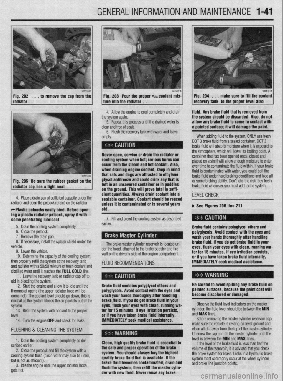
93151p18 Fig. 202 . , . to remove the cap from the
radiator
93151p17 Fig. 205 Be sure the rubber gasket on the
radiator cap has a tight seal e Fig. 203 Pour the proper *I~ coolant mix- 1 Fig. 204 . . . make sure to fill the coolant
recovery tank to the proper level also ture into the radiator . . .
.I
4. Allow the engine to cool completely and drain fluid. Any brake fluid that is removed from
ie system again.
5. Repeat this processuntil the drained water is
lear
and free of scale.
6. Flush the recovery tank with water and leave ’
mpty. the system should be discarded. Also, do not
allow any brake fluid to come in contact with
a painted surface; it will damage the paint.
When adding fluid to the system, ONLY use fresh
DOT 3 brake fluid from a sealed container. DOT 3
brake fluid will absorb moisture when it is exposed to
.a . . . , .*a. . . * .*. . .
- Never open, service or drain the radiator or
cooling system when hot; serious bums can
occur from the steam and hot coolant. Also,
when draining engine coolant, keep In mind
that cats and dogs are attracted to ethylene
glycol antifreeze and could drink any that is
left in an uncovered container or in puddles
on the ground. This will prove fatal in suffi-
4. Place a drain pan of suff i ’ 1 . . . ..I .I. 1,~ cient quantities. Always tne atmospnere, wnrcn wnr rower 1r.s oourng pomr. A
container that has been opened once, closed and
placed on a shelf will allow enough moisture to enter
over time to contaminate the fluid within. If your brake
fluid is contaminated with water, you could boil the
brake fluid under hard braking conditions and lose all
or some braking ability. Don’t take the risk, buy fresh
brake fluid whenever you must add to the system.
crenr capacrry unaer me
drain) on the radiator.
rrrasuc perwcss easuy bind; Before open-
ing a plastic radiator petcock, spray it with
some penetrating lubricant. drain coolant into a
earner. sealable container. Coolant should be reused
unless it is contaminated or is several years
old.
The brake master cylinder ~a~~~~r,~~ :A I~nnL.4 n-n 7. Fill and bleed the cooling system as described
Brake fluid contains polyglycol ethers and
polyglycols. Avoid contact with the eyes and ,LEVEL CHECK
wash your hands thoroughly after handling
brake fluid. If vou do oet brake fluid in vour
eyes, flush your eyeswith clean, runniug wa-
a-.. ‘Y-- ar -l-..n-- II -.._ I____ k See Figures 206 thru 211
.a-11-- - __-PA._ radiator and open the petcock (
- w&1--x3_ --mm.._..- . . ..-I...
5. Drain the cooling system completely.
6. Close the petcock.
7. Remove the drain pan.
If necessary, install the splash shield under the 8.
L.-l
venicie.
9. Lower the vehicle.
10. Determine the capacity of the cooling system,
then properly refill the system at the recovery tank
and radiator with a 50/50 mixture of fresh coolant and
fKm”“ll 15 IUMLC” “II- brake booster and fire- der the hood, attached to the
wall on the drivers side of the engine compartment.
FLUID RECOMMENDATIONS rer mr 13 mmures. IT eye irriIauon persim, or if you have taken brake fluid internally,
IMMEDIATELY seek medical assistance.
ala in oreerring me sysrem.
12. Start the engine and allow it to idle until the
thermostat opens (the upper radiator hose will be-
come hot). The coolant level should go down, this is
normal as the system bleeds the air pockets out of the
svstem.
IRVf!l ._._. 14. Turn the engine OFF and check for leaks. IMMEDIATELY seek medical assistance.” Brake fluid contains polyglycol ethers and
polyglycols. Avoid contact with the eyes and
wash your hands thoroughly after handling
brakefluid. If you do get brake fluid in your
eyes, flush your eyes with clean, running wa-
or if vou have taken brake fluid internallv.
Before removing the master cylinder reservoir cap,
make sure the vehicle is resting on level ground and Be careful to avoid spilling any brake fluid on
painted surfaces, because the paint coat will
become discolored or damaged.
Observe the fluid level indicators on the master
._ ._ __
‘eve1 should be between the MIN
ano
ivw unes. 13. Refill the system with coolant to the proper ter for 15 minutes; If eye irritation persists, cylinder; the tluld II
..J ..I” I....
FLUSHING & CLEANINGTHE SYSTEM
1. Drain the cooling system completely as de:
scribed earlier.
2. Close the petcock and fill the system with a
cooling system flush (clean water may also be used,
but is not as efficient).
3. Idle the engine until the upper radiator hose
gets hot. Clean, high quality brake fluid is essential to
the safe and proper operation of the brake
system. You should always buy the highest
quality brake fluid that is available. If the
brake fluid becomes contaminated, drain and
flush the system, then refill the master cylin-
der with new fluid. Never reuse any brake clean all dirt away from the top of the master cylinder.
Unscrew the cap and fill the master cylinder until the
level is between the MIN and MAX lines.
If the level of the brake fluid is less than half the
volume of the reservoir, it is advised that you check
the brake system for leaks. Leaks in a hydraulic brake
system most commonly occur at the wheel cylinder
and brake line junction points.
Page 108 of 408
ENGINEANDENGINEOVERHAUL 3-47
DO NOT rotate or turn the camshafts when re-
moving the sprockets or severe engine dam-
age will result from internal component in-
terference.
22. Align the mark on the crankshaft sprocket
with the mark on the front case. Then, move the
crankshaft sprocket 1 tooth counterclockwise.
23. Align the timing marks of the camshafts with
the marks on the rear covers.
24. Using large paper clips to secure the timing
belt to the sprockets, install the timing belt in the fol-
lowing order. Be sure camshafts-to-cylinder heads
and crankshaft-to-front cover timing marks are
aligned. Install the timing belt around the pulleys in
the following order:
a. Exhaust camshaft sprocket (front bank).
b. Intake camshaft sprocket (front bank).
c. Water pump pulley.
d. Intake camshaft sprocket (rear bank).
e. Exhaust camshaft sprocket (rear bank).
f. Tensioner pulley.
g. Crankshaft pulley.
h. Idler pulley.
*Since the camshaft sprockets turn easily,
secure them with box wrenches when in-
stalling the timing belt.
25. Align all timing marks on the crankshaft and
raise the tensioner pulley against the belt to remove
slack, snug tensioner bolt.
26. Check the alignment of all the timing marks
and remove the clips that secure the timing belt to the
camshaft sprockets.
27. Rotate the engine 1/4 turn counterclockwise,
then rotate the engine clockwise to align the timing
marks. Check that all the timing marks are in align-
ment.
28. Loosen the center bolt on the tensioner pul-
ley.
29. Using tool MD998752 or equivalent and a
torque wrench, apply 84 inch Ibs. (10 Nm) to the tool
on the tensioner. Tighten the tensioner bolt to 35 ft.
Ibs. (49 Nm) and be sure the tensioner does not ro-
tate with the bolt. 30. Rotate the crankshaft two complete turns
clockwise and let it sit for approximately five minutes.
Then, check that the set pin can easily be inserted
and removed from the hole in the auto-tensioner.
31. Remove the set wire attached to the auto-ten-
sioner
32. Measure the auto-tensioner protrusion (the
distance between the tensioner arm and auto-ten-
sioner body) to ensure that it is within 0.15-0.18 in.
(3.8-4.5mm). If out of specification, repeat adjust-
ment procedure until the specified value is obtained.
33. Check again that the timing marks on all
sprockets are in proper alignment.
34. Install the timing belt covers and all other ap-
plicable components.
3.51 Engine
p See Figure 187
1. Disconnect the negative battery cable.
2. Drain the cooling system.
Never open, service or drain the radiator or
cooling system when hot; serious burns can
occur from the steam and hot coolant. Also,
when draining engine coolant, keep in mind
that cats and dogs are attracted to ethylene
giycoi antifreeze and could drink any that is
left in an uncovered container or in puddles
on the ground. This will prove fatal in suffi-
cient quantities. Always drain coolant into a
sealable container. Coolant should be reused
unless it is contaminated or is several years
old.
3. Remove the drive belts.
4. Remove the upper radiator shroud.
5. Remove the fan and fan pulley.
6. Without disconnecting the lines, remove the
power steering pump from its bracket and position it
to the side Remove the pump brackets.
7. Remove the belt tensioner pulley bracket.
8. Without releasing the refrigerant, remove the
air conditioning compressor from its bracket and po-
sition it to the side.
9. Remove the bracket.
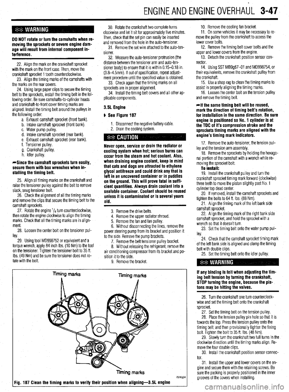
Timing marks
liming marks
Tinning marks
79245934 Fig. 187 Clean the timing marks to verify their position when aligning-3.51 engine
10. Remove the cooling fan bracket.
11, On some vehicles It may be necessary to re-
move the pulley from the crankshaft to access the
lower cover bolts.
12. Remove the timing belt cover bolts and the
upper and lower covers from the engme.
13. Detach the crankshaft position sensor con-
nector
14. Using SST MB9g67-01 and MD998754, or
their equivalents, remove the crankshaft pulley from
the crankshaft.
15. Use a shop rag to clean the timing marks to
assist in properly aligning the timing marks.
16. Loosen the center bolt on the tension pulley
and remove the timing belt.
@if the same timing belt will be reused,
mark the direction of timing belt’s rotation,
for installation in the same direction. Be sure
engine is positioned so No. 1 cylinder is at
the TDC of it’s compression stroke and the
sprockets timing marks are aligned with the
engine’s timing mark indicators.
17. Remove the auto-tensioner, the tension pul-
ley and the tension arm assembly.
18. Remove the sprockets by holding the hexago-
nal portion of the camshaft with a wrench while re-
moving the sprocket bolt.
To install: 19. Install the crankshaft pulley and turn the
crankshaft sprocket timing mark forward (clockwise)
three teeth to move the piston slightly past No. 1
cylinder top dead center.
20. If removed, install the camshaft sprockets and
tighten the bolts to 64 ft. Ibs. (88 Nm).
21, Align the timing mark of the left bank side
camshaft sprocket.
22. Align the timing mark of the right bank side
camshaft sprocket, and hold the sprocket with a
wrench so that it doesn’t turn.
23. Set the timing belt onto the water pump pul-
ley.
24. Check that the camshaft sprocket timing mark
of the left bank side is aligned and clamp the timing
belt with double clips.
25. Set the timing belt onto the idler pulley.
if any binding is felt when adjusting the tim-
ing belt tension by turning the crankshaft,
STOP turning the engine, because the pis-
tons may be hitting the valves.
26. Turn the crankshaft one turn counterclock-
wise and set the timing belt onto the crankshaft
sprocket.
27. Set the timing belt on the tension pulley.
28. Place the tension pulley pin hole so that it is
towards the top. Press the tension pulley onto the
timing belt, and then provisionally tighten the fixing
bolt. Tighten the bolt to 35 ft. Ibs. (48 Nm).
29. Slowly turn the crankshaft two full turns in the
clockwise direction until the timing marks align. Re-
move the four double clips.
30. Install the crankshaft position sensor connec-
tor.
31. Install the upper and lower covers on the en-
gine and secure them with the retaining screws. Be
sure the packing is properly positioned in the inner
grooves of the covers when installing.
Page 118 of 408
ENGINEANDENGINEOVERHAUL 3-57
Anything that generates heat and/or friction WIII
eventually burn or wear out (for example, a light bulb
generates heat, therefore its life span is limited). With
this in mind, a running engine generates tremendous
amounts of both; friction is encountered by the mov-
ing and rotating parts inside the engine and heat is
created by friction and combustion of the fuel How-
ever, the engine has systems designed to help reduce
the effects of heat and friction and provide added
longevrty. The oiling system reduces the amount of
friction encountered by the moving parts inside the
engine, while the cooling system reduces heat cre-
ated by friction and combustion If either system is
not maintained, a break-down will be inevitable.
Therefore, you can see how regular maintenance can
affect the service life of your vehicle, If you do not
drain, flush and refill your cooling system at the
proper intervals, deposits WIII begin to accumulate in
the radiator, thereby reducing the amount of heat it
can extract from the coolant The same applies to
your oil and filter; If it is not changed often enough it
becomes laden with contaminates and is unable to
properly lubricate the engine. This increases friction
and wear.
There are a number of methods for evaluating the
condition of your engine. A compression test can re-
veal the condition of your pistons, piston rings,
cylinder bores, head gasket(s), valves and valve
seats. An oil pressure test can warn you of possible
engine bearing, or oil pump failures. Excessrve oil
consumption, evidence of oil in the engine air intake
area and/or bluish smoke from the tailpipe may indi-
cate worn piston rings, worn valve guides and/or
valve seals. As a general rule, an engine that uses no
more than one quart of oil every 1000 miles is in
good condition. Engines that use one quart of oil or
more in less than 1000 miles should first be checked
for oil leaks. If any oil leaks are present, have them
fixed before determining how much oil is consumed
by the engine, especrally if blue smoke is not visible
at the tailpipe
COMPRESSION TEST
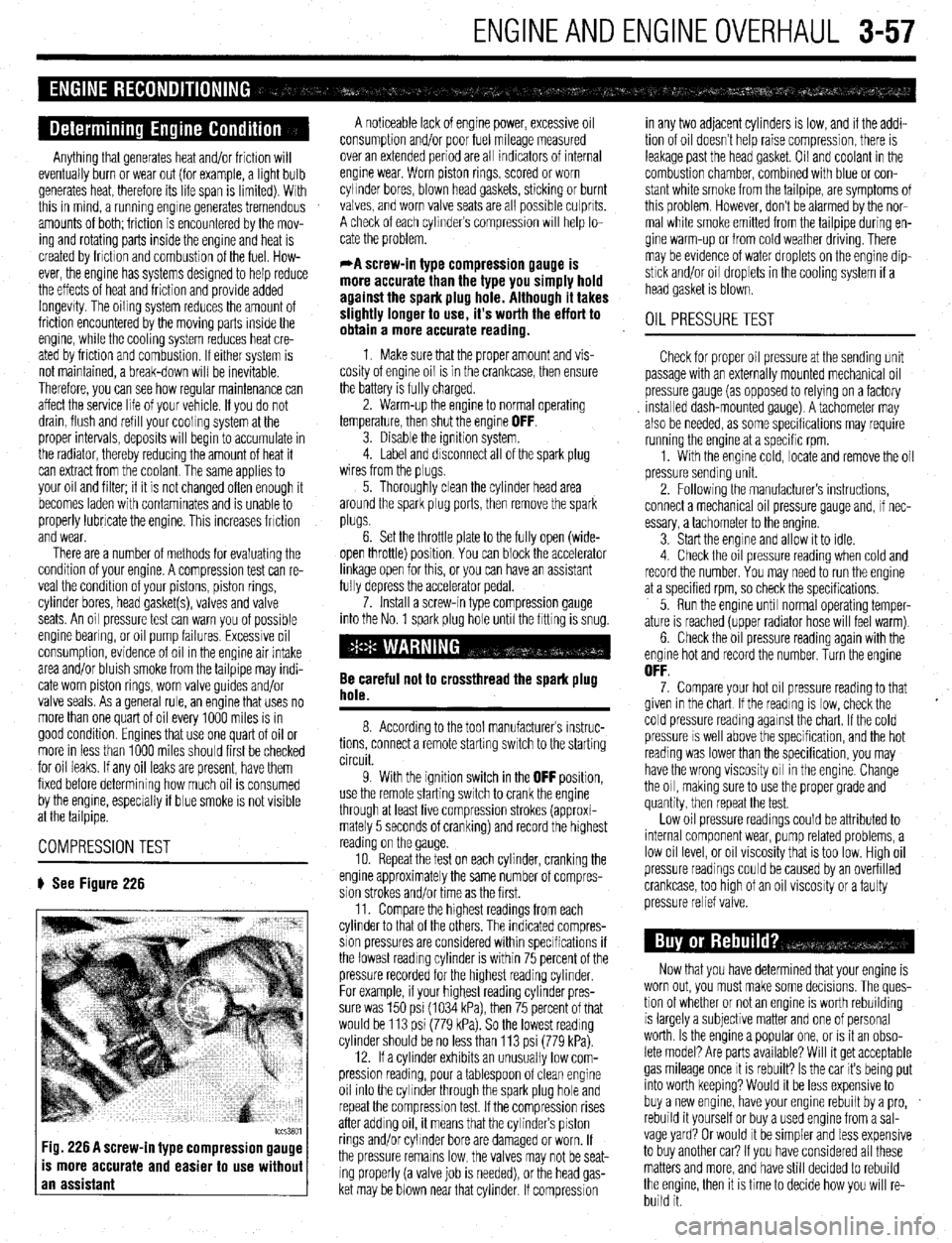
# See Figure 226
tccs3801 Fig. 226 A screw-in type compression gauge
is more accurate and easier to use without
an assistant
A noticeable lack of engine power, excessive oil
consumption and/or poor fuel mileage measured
over an extended period are all indicators of internal
engine wear. Worn piston rings, scored or worn
cylinder bores, blown head gaskets, sticking or burnt
valves, and worn valve seats are all possible culprits.
A check of each cylinders compression WIII help lo-
cate the problem.
*A screw-in type compression gauge is
more accurate than the type you simply hold
against the spark plug hole. Although it takes
slightly longer to use, it’s worth the effort to
obtain a more accurate reading.
1 Make sure that the proper amount and vis-
cosity of engine oil is in the crankcase, then ensure
the battery is fully charged.
2. Warm-up the engine to normal operating
temperature, then shut the engine
OFF. 3. Disable the ignition system.
4. Label and disconnect all of the spark plug
wires from the plugs,
5. Thoroughly clean the cylinder head area
around the spark plug ports, then remove the spark
plugs.
6. Set the throttle plate to the fully open (wide-
open throttle) position You can block the accelerator
linkage open for this, or you can have an assistant
fully depress the accelerator pedal.
7. Install a screw-in type compression gauge
into the No. 1 spark plug hole until the fitting is snug.
Be careful not to crossthread the spark plug
hole.
8. According to the tool manufacturers instruc-
tions, connect a remote starting switch to the starting
circuit.
9. With the ignition switch in the
OFF position,
use the remote starting switch to crank the engine
through at least five compression strokes (approxi-
mately 5 seconds of cranking) and record the highest
reading on the gauge
10. Repeat the test on each cylinder, cranking the
engine approximately the same number of compres-
sion strokes and/or time as the first.
11. Compare the hrghest readings from each
cylinder to that of the others. The indicated compres-
sion pressures are considered within specifications if
the lowest reading cylinder is within 75 percent of the
pressure recorded for the highest reading cylinder
For example, if your highest reading cylinder pres-
sure was 150 psi (1034 kPa), then 75 percent of that
would be 113 psi (779 kPa). So the lowest reading
cylinder should be no less than 113 psi (779 kPa).
12. If a cylinder exhibits an unusually low com-
pression reading, pour a tablespoon of clean engine
oil into the cylinder through the spark plug hole and
repeat the compression test. If the compression rises
after adding oil, it means that the cylinder’s piston
rings and/or cylinder bore are damaged or worn, If
the pressure remains low, the valves may not be seat-
ing properly (a valve job is needed), or the head gas-
ket may be blown near that cylinder. If compression in any two adjacent cylinders is low, and if the addi-
tion of oil doesn’t help raise compression, there is
leakage past the head gasket. Oil and coolant in the
combustion chamber, combined with blue or con-
stant white smoke from the tailpipe, are symptoms of
this problem. However, don’t be alarmed by the nor-
mal white smoke emitted from the tailpipe during en-
gine warm-up or from cold weather driving. There
may be evidence of water droplets on the engine dip-
stick and/or oil droplets in the cooling system if a
head gasket is blown.
OIL PRESSURETEST
Check for proper oil pressure at the sending unit
passage with an externally mounted mechanical oil
pressure gauge (as opposed to relying on a factory
Installed dash-mounted gauge). A tachometer may
also be needed, as some specifications may require
running the engine at a specific rpm.
1. With the engine cold, locate and remove the oil
pressure sending unit.
2. Followrng the manufacturers instructions,
connect a mechanical oil pressure gauge and, if nec-
essary, a tachometer to the engine.
3 Start the engine and allow it to idle.
4 Check the oil pressure reading when cold and
record the number. You may need to run the engine
at a specified rpm, so check the specifications,
5. Run the engine until normal operating temper-
ature is reached (upper radiator hose will feel warm)
6. Check the oil pressure reading again with the
engine hot and record the number. Turn the engine
OFF. 7. Compare your hot oil pressure reading to that
given in the chart If the reading is low, check the
cold pressure reading against the chart. If the cold
pressure IS well above the specification, and the hot
reading was lower than the specification, you may
have the wrong viscosity oil in the engine. Change
the oil, making sure to use the proper grade and
quantity, then repeat the test.
Low oil pressure readings could be attributed to
internal component wear, pump related problems, a
low oil level, or oil viscosity that is too low. High oil
pressure readings could be caused by an overfilled
crankcase, too htgh of an oil viscosity or a faulty
pressure relief valve.
Now that you have determined that your engine is
worn out, you must make some decisions. The ques-
tion of whether or not an engine IS worth rebuilding
is largely a subjective matter and one of personal
worth. Is the engine a popular one, or IS it an obso-
lete model? Are parts available? Will it get acceptable
gas mileage once It is rebuilt? Is the car its being put
into worth keeping? Would it be less expensive to
buy a new engine, have your engine rebuilt by a pro,
rebuild it yourself or buy a used engine from a sal-
vage yard? Or would It be simpler and less expensive
to buy another car? If you have considered all these
matters and more, and have still decided to rebuild
the engine, then it is time to decide how you will re-
build it.
Page 119 of 408
3-58 ENGINEANDENGINEOVERHAUL '
*The editors at Chilton feel that most engine
machining should be performed by a profes-
sional machine shop. Don’t think of it as
wasting money, rather, as an assurance that
the job has been done right the first time.
There are many expensive and specialized
tools required to perform such tasks as bor-
ing and honing an engine block or having a
valve job done on a cylinder head. Even in-
specting the parts requires expensive mi-
crometers and gauges to properly measure
wear and clearances. Also, a machine shop
can deliver to you clean, and ready to as-
semble parts, saving you time and aggrava-
tion. Your maximum savings will come from
performing the removal, disassembly, as-
sembly and installation of the engine and
purchasing or renting only the tools required
to perform the above tasks. Depending on
the particular circumstances, you may save
40 to 60 percent of the cost doing these your-
self.
A complete rebuild or overhaul of an engine in-
volves replacing all of the moving parts (pistons,
rods, crankshaft, camshaft, etc.) with new ones and
machining the non-moving wearing surfaces of the
block and heads. Unfortunately, this may not be cost
effective. For instance, your crankshaft may have
been damaged or worn, but it can be machined un-
dersize for a minimal fee.
So, as you can see, you can replace everything in-
side the engine, but, it is wiser to replace only those
parts which are really needed, and, if possible, repair
the more expensive ones. Later in this section, we
will break the engine down into its two main compo-
nents: the cylinder head and the engine block. We
will discuss each component, and the recommended
parts to replace during a rebuild on each. spect the component, buy the necessary parts and OVERHAULTIPS
deliver these to a shop for actual machine work.
Much of the assembly work (crankshaft, bearings, Aluminum has become extremely popular for use
piston rods, and other components) is well within the in engines, due to its low weight. Observe the follow-
scope of the do-it-yourself mechanic’s tools and abil- ing precautions when handling aluminum parts:
ities. You will have to decide for yourself the depth of
l Never hot tank aluminum parts (the caustic hot
involvement you desire in an engine repair or rebuild. 6nk solution will eat the aluminum.
l Remove all aluminum parts (identification tag,
TOOLS etc.) from engine parts prior to the tanking.
l Always coat threads lightly with engine oil or
The tools required for an engine overhaul or parts
anti-seize compounds before installation, to prevent
replacement will depend on the depth of your in-
seizure.
volvement. With a few exceptions, they will be the
l Never overtighten bolts or spark plugs espe-
tools found in a mechanic’s tool kit (see Section 1 of
this manual). More in-depth work will require some cially in aluminum threads.
When assembling the engine, any parts that will
or all of the following:
be exposed to frictional contact must be prelubed to
l A dial indicator (reading in thousandths)
provide lubrication at initial start-up. Any product
mounted on a universal base
specifically formulated for this purpose can be used,
l Micrometers and telescope gauges
* Jaw and screw-type pullers but engine oil is not recommended as a prelube in
most cases.
‘ Scraper
When semi-permanent (locked, but removable) in-
l Valve spring compressor
stallation of bolts or nuts is desired, threads should l Ring groove cleaner l Piston ring expander and compressor be cleaned and coated with Loctite@ or another simi- l Ridge reamer , lar, commercial non-hardening sealant. l Cylinder hone or glaze breaker l Plastigage@ l Engine stand
The use of most of these tools is illustrated in
this section. Many can be rented for a one-time use
from a local parts jobber or tool supply house spe-
cializing in automotive work.
Occasionally, the use of special tools is called for.
See the information on Special Tools and the Safety
Notice in the front of this book before substituting
another tool. CLEANING
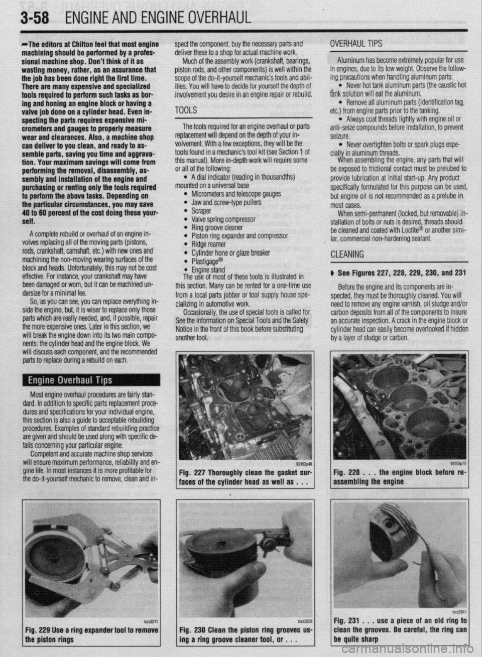
) See Figures 227, 228, 229, 230, and 231
Before the engine and its components are in-
spected, they must be thoroughly cleaned. You will
need to remove anv enaine varnish, oil sludoe and/or
c arbon deposits from ail of the componentsio insure
a In accurate inspection. A crack in the engine block or
c :ylinder head can easily become overlooked if hidden
t ry a layer of sludge or carbon.
Most engine overhaul procedures are fairly stan-
dard. In addition to specific parts replacement proce-
dures and specifications for your individual engine,
this section is also a guide to acceptable rebuilding
procedures. Examples of standard rebuilding practice
are given and should be used along with specific de-
tails concerning your particular engine.
Competent and accurate machine shop services
will ensure maximum performance, reliability and en-
gine life. In most instances it is more profitable for
the do-it-yourself mechanic to remove, clean and in- Fig. 227 Thoroughly clean the gasket sur-
faces of the cylinder head as well as . . .
Fig. 229 Use a ring expander tool to remove
the piston rings
fccs3911 ::“,z s,rpuse,a piece of fn old ring to 1
clean the grooves Be careful the ring can
230 Clean the piston ring grooves us-
ing a ring groove cleaner tool, or . . .
Page 124 of 408
ENGINEANDENGINEOVERHAUL 3-63
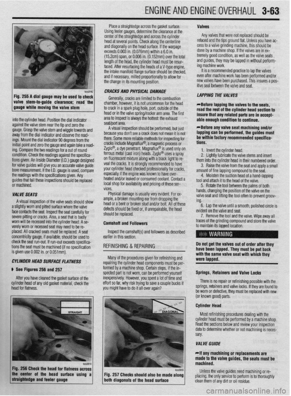
Place a straightedge across the gasket surface. Valves
Using feeler gauges, determine the clearance at the
center of the straightedge and across the cylinder Any valves that were not replaced should be
head at several points. Check along the centerline refaced and the tips ground flat. Unless you have ac-
and diagonally on the head surface. If the warpage cess to a valve grinding machine, this should be
exceeds 0.003 in. (0.076mm) within a 6.0 in. done by a machine shop. If the valves are in ex-
(152cm) span, or 0.006 in. (0.152mm) over the total tremely good condition, as well as the valve seats
length of the head, the cylinder head must be resur- and guides, they may be lapped in without petform-
,
I mg macnme worK.
4
It is a recnmmended practice to lap the valves faced. After resurfacing the heads of a V-type engine
the intake manifold flange surface should be checker,
and if necessary, milled proportionally to allow for
the change in its mounting position. _ - _ _ _ .- - - _
even after machine work has been p&formed and/or
new valves have been purchased. This insures a pos-
itive seal between the valve and seat.
-guide clearance; the 1
read
. .
into the cylinder head. Position the dial indicator
against the valve stem near the tie and zero the
gauge. Grasp the valve stem and’wiggle towards and
away from the dial indicator and observe the read-
ings. Mount the dial indicator 90 degrees from the
initial point and zero the gauge and again take a read-
ing. Compare the two readings for a out of round
condition. Check the readings against the specifica-
tions given. An Inside Diameter (I.D.) gauge designed
for valve guides will give you an accurate valve guide
bore measurement. If the I.D. gauge is used, compare
the readings with the specifications given. Any CRACKS AND PHYSICAL DAMAGE
Generally, cracks are limited to the combustion
chamber, hbwever, it is not uncommon for the head
to crack in a spark plug hole, port, outside of the
head or in the valve spring/rocker arm area. The first
area to inspect is always the hottest: the exhaust
.I *
seawpon area.
8 I .,“““I llly”Lv”l~ .ml”“l” - plr”llll”“, ““I ,“a’
because you don’t see a crack does not mean it is not
there. Some more reliable methods for inspecting for
cracks include Magnaflux? a magn$i,c process or
Zyglo? a dye penetrant. Ma{ -’
InatluxW IS used only on
ferrous metal (cast iron) heat Is. Zyglo@ uses a spray
on fluorescent mixture along with a black light to re-
veal the cracks. It is strongly recommended to have
your cylinder head checked professionally for cracks,
especially if the engine was known to have over-
I .* I,. ..^.. LAPPING THE VALVES
*Before iaoaino the valves to the seats,
read the rest of the cylinder head section to
insure that any related parts are in accept-
able enough condition to continue.
*Before anv valve seat machining and/or
lapping can be performed, the guides must
be within factory recommended specifica-
tions.
1. Invert the cylinder head.
2. Linhtlv Iuhrir;rB the valve stems and insert
-. _ ~ . . . . . .--.._-._
them into the cylinder head in their numbered order.
3. Raise the valve from the seat and apply a small
amount of fine lanninn compound to the seat.
4.
i guides that fail these inspections should be replaced nearea analor ieaKea or consumea coolant. Contact a Moisten the suction head of a hand-lapping
tool and attach it to the head of the valve.
i or machined. local shop for availability and pricing of these ser-
5. Rotate the tool between the palms of both
I vices.
I
VALVE SEATS Physical damage is usually very evident. For ex- hands, changing the position of the valve on the
valve seat and lifting the tool often to prevent groov-
A visual inspection of the valve seats should show
amnb P hrnbn mntlntinn ear from dropping the I and/or bolt. All of these ing.
.a,... . 6. Lap the valve until a smooth, polished circle is
a slightly worn and pitted surface where the valve
face contacts the seat. Inspect the seat carefully for
severe pitting or cracks. Also, a seat that is badly
worn will be recessed into the cylinder head. A se-
verely worn or recessed seat may need to be re- uetecIs SIIOUIO oe nxea or, IT unrepairaole, me neaa
should be replaced.
Camshaft and Followers evid
7
traces of the grinding corn
to maintain its lapped loca lent on the valve and seat.
‘. Remove the tool and the valve. Wipe away all
pound and store the valve
placed: All cracked seats must be replaced. A seat
concentricity gauge, if available, should be used to
check the seat run-out. If run-out exceeds specifica-
tions the seat must be machined (if no soecification
is given use 0.002 in. or O.O51mt$. Inspect the camshaft(s) and followers as described
earlier in this section.
REFINISHING & REPAIRING Do not get the valves out of order after they
have been lapped. They must be put back
: ..^^ I... --I:^:-L!-- --A
Many of the procedures gIveI
WI WIIIIISIIIIIIJ ~IIU repairing the cylinder head components must be per-
formed by a machine shop. Certain steps, if the in-
spected part is not worn, can be performed yourself
inexpensively. However, you spent a lot of time and
effort so far, why risk trying to save a couple bucks if
you might have to do it all over again?
I- with the same valve seat with which they
were lapped.
Springs, Retainers and Valve locks
There is no repair or refinishing possible with the
springs, retainers and valve locks. If they are found to
be worn or defective, they must be replaced with new
lor known nnod narts CYLtNDEt? HEAD SURFACE FLATNESS
) See Figures 256 and 257
After you have cleaned the gasket surface of the
cylinder head of any old gasket material, check the
head for flatness.
\- - a---r r- .-.
Cylinder Head
Most refinishing procedures dealing with the
VALVE GWDE
elf any machining or replacements are
e valve guides, the seats must be
Fig. 257 Checks should also be made along Unless the valve guides need machining or re-
placing, the only service to perform is to thoroughly‘
clean them of any dirt or oil residue.
Page 144 of 408
EMISSION CONTROLS 4-2
CRANKCASEVENTILATIONSYSTEM 4-2
OPERATION 4-2
COMPONENTTESTING 4-2
REMOVAL &INSTALLATION 4-2
EVAPORATIVEEMISSIONCONTROLS 4-2
OPERATION 4-2
COMPONENTTESTING 4-3
REMOVAL&INSTALLATION 4-4
EXHAUSTGASRECIRCULATION
SYSTEM 4-5
OPERATION 4-5
COMPONENTTESTING 4-5
REMOVAL&INSTALLATION 4-6
ELECTRONIC ENGINE CONTROLS 4-7
ENGlNECONTROLUNIT/POWERTRAIN
CONTROLMODULE(ECU/PCM) 4-7
OPERATION 4-7
REMOVAL&INSTALLATION 4-7
OXYGENSENSOR 4-8
OPERATION 4-8
TESTING 4-8
REMOVAL&INSTALLATION 4-8
IDLEAIRCONTROLMOTOR 4-9
OPERATION 4-9
TESTING 4-9
REMOVAL&INSTALLATION 4-9
ENGINECOOLANTTEMPERATURE
SENSOR 4-10
OPERATION 4-10
TESTING 4-10
REMOVAL&INSTALLATION 4-10
INTAKEAIRTEMPERATURESENSOR 4-10
OPERATION 4-10
TESTING 4-11
REMOVAL&INSTALLATION 4-11
MASSAIRFLOWSENSOR 4-11
OPERATION 4-11
TESTING 4-11
REMOVAL&INSTALLATION 4-11
MANIFOLDABSOLUTEPRESSURE
SENSOR 4-12
OPERATION 4-12
TESTING 4-12
REMOVAL&INSTALLATION 4-13
THROTTLEPOSITIONSENSOR 4-13
OPERATION 4-13
TESTING 4-13
REMOVAL&INSTALLATION 4-13
CAMSHAFT POSITIONSENSOR 4-14
OPERATION 4-14
TESTING 4-14
REMOVAL&INSTALLATION 4-14
CRANKSHAFTPOSlTlONSENSOR/CRANK
ANGLE SENSOR 4-14
OPERATION 4-14 I
TESTING 4-15 REMOVAL&INSTALLATION 4-15
COMPONENT LOCATIONS 4-16
OBD-1 TROUBLE CODES 4-26
GENERALINFORMATION 4-26
CHECKENGINVMALFUNCTION
INDICATOR LIGHT 4-26
SERVICEPRECAUTIONS 4-26
READING CODES 4-26
WITHASCANTOOL 4-26
WITHOUTASCANTOOL 4-27
CLEARINGCODES 4-27
DIAGNOSTICTROUBLECODES 4-27
OBD-II TROUBLE CODES 4-27
GENERALINFORMATION 4-27
READING CODES 4-27
WITHASCANTOOL 4-27
WITHOUTASCANTOOL 4-27
CLEARINGCODES 4-28
WITHASCANTOOL 4-28
WITHOUTASCANTOOL 4-28
DIAGNOSTICTROUBLECODES 4-28
FLASH OUTCODELIST 4-32
VACUUM DIAGRAMS 4-36
Page 169 of 408
4-26 DRIVEABILITYAND EMISSIONS CONTROLS
The Powertrain Control Module (PCM) monitors
the signals of input and output sensors, some all the
time and others at certain times and processes each
signal. When the PCM notices that an irregularity has
continued for a specified time or longer from when
the irregular signal was initially monitored, the PCM
judges that a malfunction has occurred and will
memorize the malfunction code. The code is then
stored in the memory of the PCM and is accessible
through the data link (diagnostic connector) with the
use of an electronic scan tool or a voltmeter.
CHECK ENGINE/MALFUNCTION
INDICATOR LIGHT
Among the on-board diagnostic items, a check
engine/malfunction indicator light comes on to notify
the driver of a emission control component irregular-
ity. If the irregularity detected returns to normal or the
PCM judges that the component has returned to nor-
mal, the check engine/malfunction indicator light will
be turned off Moreover, if the ignition is turned OFF
and then the engine is restarted, the check
engine/malfunction indicator light will not be turned
on unttl a malfunction is detected.
The check engine/malfunction indicator light will
come on immediately after the ignition switch is
turned ON. The light should stay lit for 5 seconds
and then will go off. This Indicates that the check en-
gine/malfunction indicator lamp is operating nor-
mally. This does not signify a problem with the sys-
tem.
*The check engine/malfunction indicator
lamp will come on when the terminal for the
ignition timing adjustment is shorted to
ground. Therefore, it is not abnormal that the
light comes on even when the terminal for ig-
nition timing is shorted at time of ignition
timing adjustment.
To test the light, perform the following:
1. Turn the ignition switch ON. Inspect the check
engine/malfunction indicator lamp for Illumination.
2. The light should be lit for 5 seconds and then
should go out.
3. If the lamp does not illuminate, check for open
circuit In the harness, blown fuse or blown bulb.
SERVICE PRECAUTIONS
l Before attachrng or detaching the PCM harness
connectors, make sure the ignition switch is OFF and
the negative battery cable is disconnected to avoid
the possibility of damage to the PCM.
l When performing PCM input/output signal di-
agnosis, remove the pin terminal retainer from the
connectors to make it easier to insert tester probes
into the connector.
l When attaching or detaching pin connectors ,
from the PCM, take care not to bend or break any pin
terminals. Check that there are no bends or breaks on
PCM pin terminals before attempting any connec-
tions.
l Before replacing any PCM, perform the PCM
input/output signal diagnosis to make sure the PCM
is functioning properly.
l When measuring supply voltage of PCM-con-
trolled components with a circuit tester, separate 1
tester probe from another. If the 2 tester probes acci-
dentally make contact with each other during mea-
surement, a short circuit WIII result and damage the
PCM.
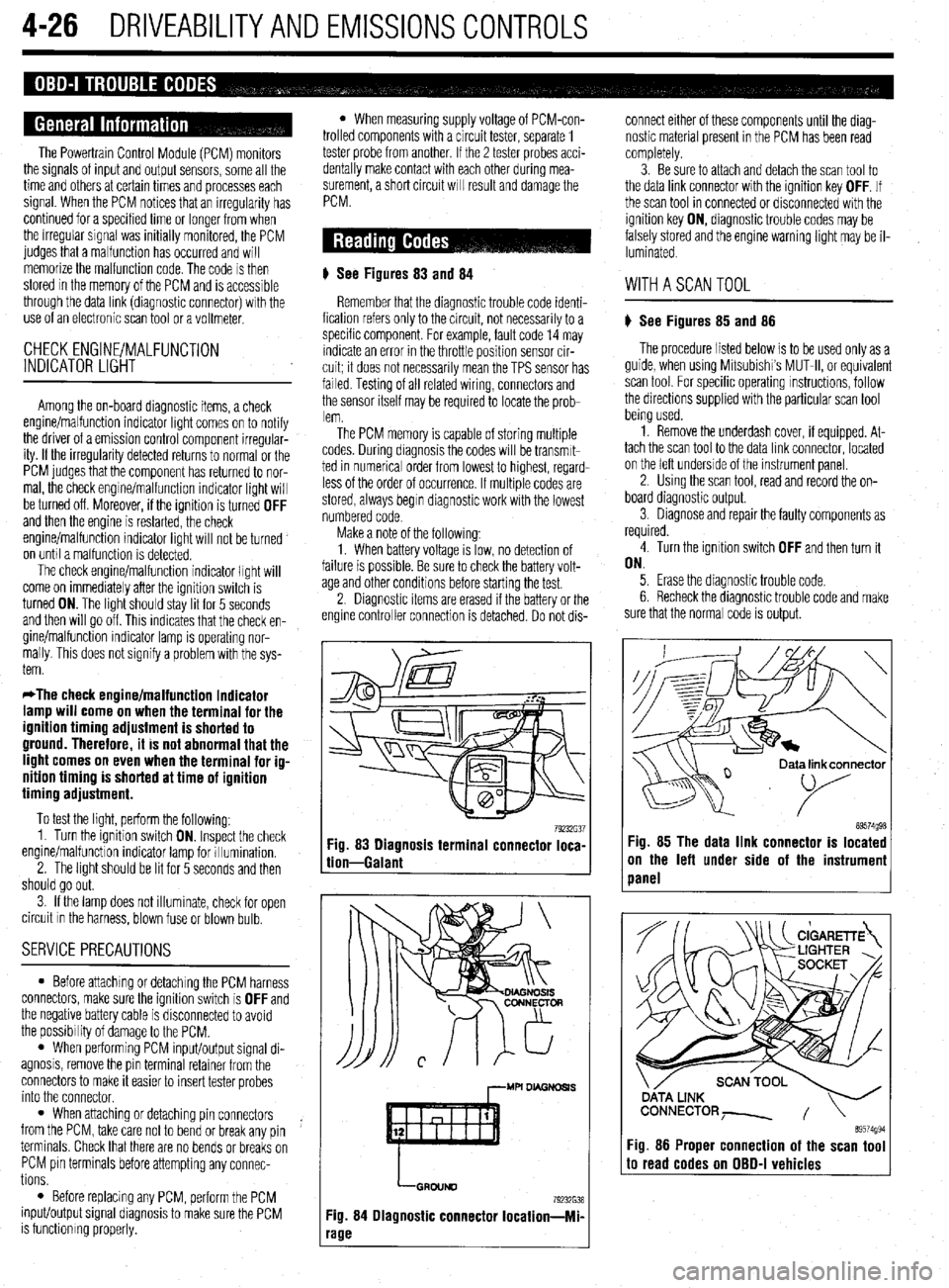
# See Figures 83
and 84
Remember that the diagnostic trouble code identi-
fication refers only to the circuit, not necessarily to a
specific component. For example, fault code 14 may
indicate an error in the throttle position sensor cir-
cuit; it does not necessarily mean the TPS sensor has
failed Testing of all related wiring, connectors and
the sensor itself may be required to locate the prob-
lem.
The PCM memory is capable of storing multiple
codes. During diagnosis the codes will be transmlt-
ted in numerical order from lowest to highest, regard-
less of the order of occurrence. If multiple codes are
stored, always begin diagnostic work with the lowest
numbered code
Make a note of the following:
1. When battery voltage IS low, no detection of
failure is possible. Be sure to check the battery volt-
age and other conditions before starting the test.
2. Diagnostic items are erased if the battery or the
engine controller connection is detached. Do not dis- connect either of these components until the diag-
nostic material present in the PCM has been read
completely.
3. Be sure to attach and detach the scan tool to
the data link connector with the ignition key OFF. If
the scan tool in connected or disconnected with the
ignition key ON, diagnostic trouble codes may be
falsely stored and the engine warning light may be il-
luminated. WITHASCANTOOL
) See Figures 85 and 86
The procedure listed below is to be used only as a
guide, when using Mitsubishi’s MUT-II, or equivalent
scan tool. For specific operating instructions, follow
the directions supplied with the particular scan tool
bemg used.
1. Remove the underdash cover, if equipped. At-
tach the scan tool to the data link connector, located
on the left underside of the instrument panel.
2. Using the scan tool, read and record the on-
board diagnostic output.
3. Diagnose and repair the faulty components as
required
4. Turn the ignition switch OFF and then turn it
ON.
5. Erase the diagnostic trouble code.
6 Recheck the diaanostic trouble code and make
sure that the normal &de is output.
79232G37 89574g98 Fig. 83 Diagnosis terminal connector loca-
tion-Galant Fig. 85 The data link connector is located
on the left under side of the instrumeni
panel
,--MU DL4GNDSl.S
LGRDIJND
79232638
Fig. 84 Diagnostic connector Iocation-Mi-
‘age
ata link connector
89574994 Fig. 86 Proper connection of the scan tool to read codes on OBD-I vehicles
Page 310 of 408
SUSPENSION AND STEERING 845
144-188 ft. Ibs. (200-260 Nm). Rotate the hub ing knuckle and install a new nut. Tighten to 52 ft. 3. Remove the cotter pin, halfshaft nut and
to seat the bearing.
Ibs. (72 Nm). washer.
e. Mount the knuckle assembly in a vise.
12. Install the halfshaft into the hub/knuckle as- 4. If equipped with ABS, remove the Vehicle
Check the hub assembly turning torque and end- sembly.
Speed Sensor (VSS).
play as follows: 13. Install the two front strut lower mounting bolts
5. Remove the caliper and brake pads. Support
l Using a torque wrench and socket
and tighten to 80-94 ft. Ibs. (110-130 Nm) on Mirage
the caliper out of the way using wire.
MB990998 or equivalent, turn the hub in the or 65-76 ft. Ibs. (90-105 Nm) on Diamante models. 6. Remove the brake rotor from the hub assembly.
knuckle assembly. Note the reading on the torque
14. Install the tie rod end and tighten the nut to 7. Disconnect the upper ball joint from the
wrench and compare to the desired reading of 16
25 ft. lbs. (34 Nm) for Mirage and 21 ft. Ibs. (29 Nm) steering knuckle and pull the knuckle outward.
inch Ibs. (1.8 Nm) or less. This is known as the ‘on Diamante models
8. From the back of the knuckle, remove the
breakaway torque.
15. Install the brake disc and caliper assembly. ‘four bolts securing the hub to the knuckle.
l Check for roughness when turning the
16. If equipped with Active-ECS, connect the
9. Remove the hub and bearing assembly from
bearing.
height sensor and tighten the mounting bolt to 15 ft.
the knuckle.
0 Mount a dial indicator on the hub so the
Ibs. (20 Nm).
pointer contacts the machined surface on the hub.
17. Install the front speed sensor, if removed.
*The hub assembly is not serviceable and
l Check the end-play.
18. Install the washer and new locknut to the end should not be disassembled.
l Compare the reading to the limit of 0.002
in. (0.05mm). of the halfshaft. Tighten the locknut snugly to To install: 144-188 ft. Ibs. (200-260 Nm).
f. If the starting torque or the hub end-play
19. Install the tire and wheel assembly onto the 10. Install the hub to the steering knuckle and
are not within specifications while the nut is tighten the mounting bolts to 65 ft. Ibs. (88 Nm).
vehicle.
11.
tightened to 144-188 ft. Ibs. (200-260 Nm), the
Lower the vehicle to the ground. Connect the upper ball joint to the steering
20.
bearing, hub or knuckle have probably not been ‘knuckle and tighten the self-locking nut to 21 ft. Ibs.
(28 Nm).
installed correctly. Repeat the disassembly and 1994-98 Galant 12.
‘assembly procedure and recheck starting torque Install the axle washer and nut. Tighten the
and end-play. nut to 145-188 ft. Ibs. (200-260 Nm).
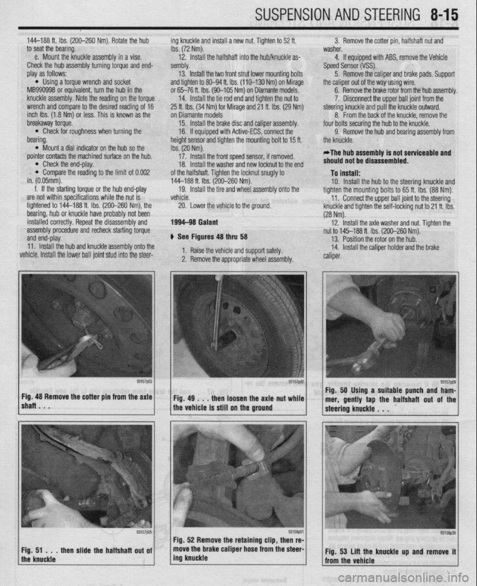
+ See Figures 48 thru 58 13. Position the rotor on the hub.
11. Install the hub and knuckle assembly onto the
vehicle. Install the lower ball joint stud into the steer- 1. Raise the vehicle and support safely. 14. Install the caliper holder and the brake
2. Remove the appropriate wheel assembly. ” caliper.
lshaRBmV * “57pa3~ ~Fig.4g~..thenloosehtheaxlattut~~;.~ Fig. 48 Remove the cotter pm from the axle Fig. 50 Using a suitable punch and ham-
mer, gently tap the halfshaft out of the
the vehicle is still on the ground
Page 320 of 408
SUSPENSION AND STEERING 8-25
1994-00 Galant and 1997-00 Diamante
4. Remove the retainer bolts and the stabilizer
..- 8, Loosely in”,“,, +I?,, r+&,il;7nr kn- h.~r.l,,d” -..
1. Raise and safely support the vehicle securely he bushing.
the vehicle.
on jackstands.
7er hnr with FI wmnph Remnun (1 Alinn th
2. Remove the wheel and tire assembly.
3. Support the rear axle using a jack or other
suitable device.
4. Remove the trailing arm-to-knuckle connec-
tion,
5. Remove the trailing arm-to-body mounting
n~~““yll-““!~ (1II” fWll”“C LllG llcllllll$j a,,,,. To install:
6. Install the trailing arm and install the trailing
arm-to-body mounting through-bolt. Tighten the bolt
to 99-114 ft. Ibs. (137-157 Nm).
7. Install the trailing arm-to-knuckle connection. Dar brackets. Hemove t
5. Hold the stabilL_. __. . . _ . .._..“... ..I . .._._
the self-locking nut.
6. Once the stabilizer bar nut is removed, re-
move the joint cups and stabilizer rubber bushing.
7. Hold the stabilizer link with a wrench and re-
move the self-locking nuts. Remove the stabilizer
link.
8. Lower the jack supporting the rear axle
in a slight gap between the rear sus-
? body of the vehicle.
! the stabilizer bar.
IL_ L__ I__ _)----- .-- .-J JAI.... slightly. Mainta
pension and thf
9. Remow
10. Inspect LIIB uar 101 uamage, wear ana aereno-
ration and replace as required.
-Fe c--a-...
1 IIIJMII UK 3La”III‘w “ill “lduKm “II
“. , ,,LY,, ,,ie side locating markings on the stabi-
lizer bar, so that the marking on the bar extends ap-
proximately 0.39 inches (1Omm) from the outer edge
of the mounting bracket, on both sides.
10. With the stabilizer bar properly aligned,
tighten the mounting bracket bolts to 28 ft. Ibs. (39
Nm).
11. Connect the stabilizer links to the damper fork
andihe stabilizer bar. Tighten the locking nuts to 28
ft. Ibs. (38 Nm).
12. Lower the vehicle and connect the negative
8.. Ia
mery came.
Tighten the bolt to 85-99 ft. Ibs. (118-137 Nm).
nemove me axle suppon
9. Install the wheel and tire
10. Lower the vehicle. aewce.
assembly.
I 0 Insran: 11, Install the stabilizer bar into the vehicle. Raise
the rear axle and suspension into place.
12. Install the stabilizer link into the stabilizer ba
Ir
ADJUSTMENT anfi indc4ll 33 ft. Ibs. (45 Nm).
13. Install the ioint __-_ _.._ __
1. Raise and safely support the vehicle securely the link. Ins’
..I.,
Mlhiln hnlrii, tall a rkW self~locking n
lll~llG llUlulng the stabi” ” ’ ’ ’
wrench, tighten the self,
of the stabilizer link is v
ihe hub and bearing assembly.
5. Support the rear axle using a jack or other
suitable device.
6. Remove the lower shock absorber-to-trailing
arm connection. ocking nut. Tighten the nut to
ClrnC 2nd ?$bilizer rubber to
ut onto the link.
nzer nnK oall studs with a
-locking nut so the protrusion
within 0.354-0.433 in.
I stabilizer bar bushings,
>+nn thn hnk In -I A u (9-llmm).
14. Install the cente
brackets and bolts. Tiqt Mirage
*Never disassemble the rear hub bearing.
The wheel bearing is serviced by replace-
ment of the hub.
1. Raise and safely support the vehicle.
2. Remove the rear wheel.
3. Remove the caliper and brake disc of brake 1992-96 biamante
on IacKsranos.
2. Remove the wheel and tire assembly
3, Remove thn hralm rntnr 4. Remove1
7. Remove the stabilizer bar link-to-trailing arm
connection.
8. Remove the tie rod end-to-trailing arm con-
nection.
9. Remove the lower control arm-to-trailing arm
connection.
10. Remove the trailing arm-to-body mounting
through-bolt and remove the trailing arm. Nm).
15. Install the parking
sensor installation bolt.
, , I oraxe cat * ale ar
member bracket and tighten
i Nm). Tighten the crossmem-
A to 94 ft. Ibs. (130 Nm). 16. Install the cross
the bolt to 61 ft. Ibs. (8!
ber bracket mounting nl
17. Install the rubbe
locking nuts onto the cro:
the nuts to 80-94 fl. Ibs. (
18. Lower the vehicle. id rear speed drum.
4. Remove the dust cab and tighten the flange ll”, *lb+ to 130 ft. Ibs. (180 Nm).
5. Using a dial indicator, measure wheel bear-
!r insulators and new seif-
ismemoer ’ brackets. Tighten
[110-130 Nm). ing end-play. The maximum limit for end-play is
o.oc-- ‘^ -- rzu mcnes (u.usmm).
arol
tanc
sisk 6. Using a spring scale and a rope wrapped
md the bolts, measure the rotary sliding resis-
e of the bearing/hub. The maximum limit for re-
mce is 4 Ibs. (19 N).
7. If any of the readings exceed the specifica-
To install:
11. Install the trailing arm and install the trailina Diamante and 1994-98 Gal&i
t tions, replacement of the hub is required.
8. Install the dust cap.
9. Install the brake disc and caliper, or brake
negative battery ( sble.
;“I,-.
I support the vbhlblG.
stabilizer links by removing
Alizer bar mounting brackets
from the vehicle.
lonents for wear or damage,
ded. drum.
10. Install the rear wheel assembly and lower the
vehicle to the floor.
*
1990-93 Galant
*Vehicles equipped with rear disc brakes
use a sealed hub and bearing assembly,
which requires no adjustment. Drum brake
models are
adjusted using the following pro- arm-to-body mounting through-bolt. Tighten the bolt
to 101-116 ft. Ibs. (140-160 Nm). ) See Figure 72
12. Install the trailing arm-to-lower control arm
1. Disconnect the I
connection. Tighten the bolt to 101-116 ft. Ibs.
(140-160 Nm). 2. Raise and safely
13. Install the tie rod end-to-trailing arm connec- 3. Disconnect the I
tion. Tighten the nut to 21 ft. Ibs. (29 Nm). the self-locking nuts.
14. Install the stabilizer bar link-to-trailing arm 4. Remove the stat
connection. Tighten the nut to 29 ft. Ibs. (40 Nm). and bushings.
15. Install the lower shock absorber-to-trailing
5. Remove the bar
arm connection. Tighten the bolt to 65 ft. Ibs. (90 6. Inspect all comr
. and replace parts as nee
Nrn).
16. Remove the axle support device.
17. Install the hub and bkaring assembly,
18. Install the brake rotor.
19. Install the wheel and tire assembly.
20. Lower the vehicle.
REMOVALANDINSTALLATION
1990-93 Gaiant
1. Raise and support the vehicle safely.
2. Place a jack under the rear axle and suspen- To install:
7 InstA the dnhili cedure. ._._ . . .._ -.--.. lzer bar into the vehicle.
1. Raise the vehicle and support it safely.
2. Remove the wheel and tire assemblies.
3. If equipped with rear disc brakes, remove the
caliper assembly.
4. Remove the grease cap and the hub nut.
5. Tighten the wheel bearing nut to 20 ft. Ibs. (27
Nm) while rotatir ” ”
6. Back off th
load and then tighten it to 7 ft. Ibs. (10 Nm).
7. Install the nut lock and a new cotter pin.
8. If brake caliper was removed, reinstall.
9. Install the wheel and lower the vehicle.
Diamante and lQQ44 Galant 10 tne mum/hub.
ie adjusting nut to remove the pre-
Sian assembly.
3. Remove the self-locking nuts and crossmem-
ber bracket.
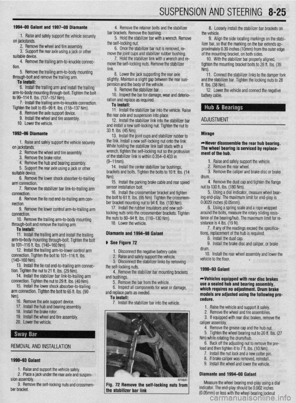
93158P61 Fig. 72 Remove the self-locking nuts from Measure the wheel bearing end-play using a dial
the stabilizer bar link indicator. The end-play should be 0.002 inches
a (0.05mm) or less with the wheel bearing locknut
Page 322 of 408
8-26 SUSPENSION AND STEERING
torqued to specifications. The wheel bearings are
sealed units and are not adjustable. If defective, re-
placement is the only option.
REMOVAL &INSTALLATION
Mirage
7996-92 MODELS
1. Raise the vehicle and support safely.
2. Remove the tire and wheel assembly.
3. If equipped with rear disc brakes, remove the
caliper from the disc and remove the brake disc.
4. Remove the dust cap and bearing nut. Do not
use an air gun to remove the nut.
5. Remove the outer wheel bearing.
6. Remove the drum and/or axle hub with the
inner wheel bearing and the grease seal.
7. Remove the grease seal and remove the inner
bearing.
To install: 8. Lubricate the inner bearing and install to the
drum or hub.
9. Install a new grease seal.
10. To determine if the self-locking nut is
reusable:
a. Screw in the self-locking nut until about
0.07-0.11 in. (2-3mm) of thread is visible under
the nut.
b. Measure the torque required to turn the
self-locking nut counterclockwise.
c. The lowest allowable torque is 48 inch Ibs.
(6 Nm). If the measured torque is less than the
specification, replace the nut.
11. Install the drum and/or hub to the vehicle.
12. Lubricate and install the outer wheel bearing
to the spindle.
13. Tighten the self-locking nut to 108-145 ft.
Ibs. (150-200 Nm).
14. Set up a dial indicator and measure the end-
play while moving the hub or drum in and out. If the
endplay exceeds 0.008 in. (0.002mm) retorque the
nut. If still beyond the limit, replace the bearings.
15. Install the grease cap and wheel assembly.
7993-60 MODELS
*Never disassemble the rear hub bearing.
The wheel bearing is serviced by replace-
ment of the hub.
1. If equipped with ABS, remove the wheel
speed sensor.
2. Raise and safely support the vehicle.
3. Remove the rear wheel.
4. Remove the caliper and brake disc or brake
drum.
5. Remove the dust cap and flange nut.
6. Remove the rear hub assembly.
To install: 7. Install the rear hub assembly using a new
flange nut. Tighten the flange nut to 130 ft. Ibs. (180
Nm).
8. install the dust cap.
9. Install the wheel speed sensor if removed.
The air gap should be 0.012-0.035 in. (0.3-0.9mm).
10. Install the brake disc and caliper, or brake
drum.
11. Install the rear wheel assembly and lower the
vehicle to the floor.
1990-93 Galant
DRUM BRAKE VEHICLES
1. Raise the vehicle and support it safely.
2. Remove the wheel and tire assemblies.
3. Remove the grease cap and the hub nut.
4. Remove the brake drum. The outer bearing
will fall out while the drum is coming off. Do not drop
it. Remove the hub and rotor assembly.
5. Pry out and discard the oil seal.
6. Remove the inner bearing.
*Check the bearing races. If any scoring,
heat checking or damage is noted, they
should be replaced. When bearing or races
need replacement, replace them as a set.
7. If the bearings and races are to be replaced,
drive out the race with a brass drift.
To install: 8. Before installing new races, coat them with
wheel bearing grease. Drive into place with proper
size driver. Make sure they are fully seated.
9. Thoroughly pack the bearings and lubricate
the hubs with wheel bearing grease. Install the inner
bearing and coat the lip and rim of the grease seal
with grease. Drive the seal into place with a seal dri-
ver.
10. Install the drum assembly on the axle.
11, Lubricate and install the outer wheel bearing,
washer and nut. To properly adjust the wheel bearing
preload:
a. Tighten the wheel bearing nut to 20 ft. Ibs.
(27 Nm) while rotating the drum.
b. Back off the adjusting nut to remove the
preload, then tighten it to 7 ft. Ibs. (10 Nm).
c. Install the nut lock and a new cotter pin.
12. Install the wheel and lower the vehicle.
O/SC BRAKE VEHICLES
1. Raise the vehicle and support safely.
2. Remove the tire and wheel assembly.
3. Remove the bolt(s) holding the speed sensor
bracket to the knuckle and remove the assembly from
the vehicle.
The speed sensor has a pole piece projecting
from it. This exposed tip must be protected
from impact or scratches. Do not allow the
oole oiece to contact the toothed wheel dur-
in0 removal or installation.
4. Remove the caliper from the brake disc and
suspend with a wire.
5. Remove the brake rotor.
6. Remove the grease cap, locking nut and
tongued washer.
7. Remove the rear hub and bearing assembly.
*The rear hub assembly can not be disas-
sembled. If bearing replacement is required,
replace the assembly as a unit.
8. If replacing the hub assembly, remove the
two bolts securing the speed sensor ring to the hub.
To install: 9. Install the speed sensor to the hub and bear-
ing assembly. Tighten the mounting bolts to 8 ft. Ibs.
(11 Nm). 10. Install the hub and bearing assembly to the
axle shaft.
11, Install the tongued washer and a new locking
nut. Tighten the locknut to 144-188 ft. Ibs. (200-260
Nm). Once the locknut has been properly torqued,
crimp the nut flange over the slot in the spindle, and
install the grease cap.
12. Install the brake caliper and rotor.
13. Install the speed sensor and tighten the
mounting bolt to 8 ft. Ibs. (11 Nm).
14. Install the tire and wheel assembly.
Be sure to pump the brake pedal until it’s
firm, before moving vehicle.
1994-00 Galant
DRUM BRAKE VEHICLES
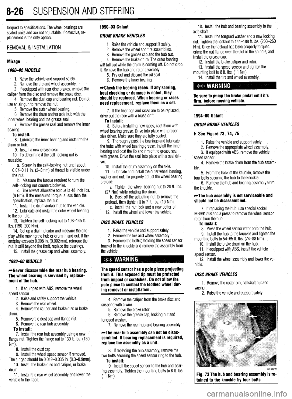
) See Figure 73, 74, 75
1. Raise the vehicle and support safely.
2. Remove the appropriate wheel assembly.
3. If equipped with ABS, remove the vehicle
speed sensor.
4. Remove the brake drum from the hub assem-
bly.
5. From the back of the knuckle, remove the
four bolts securing the hub to the knuckle.
6. Remove the hub and bearing assembly from
the knuckle.
*The hub assembly is not serviceable and
should not be disassembled.
7. If replacing the hub, use special socket
MB991248 and a press to remove the wheel sensor
rotor from the hub.
To install: 8. Press the wheel sensor rotor onto the hub.
9. Install the hub to the knuckle and tighten the
mounting bolts to 54-65 ft. Ibs. (74-88 Nm).
10. Install the brake drum on the hub.
11. If equipped with ABS, install the vehicle
speed sensor.
12. Install the wheel assembly and lower the ve-
hicle.
O/SC BRAKE VEHICLES
1. Remove the cotter pin, halfshaft nut and
washer.
2. Raise the vehicle and support safely.
Fig. 73 The hub and bearing assembly is re-
tained to the knuckle by four bolts