change time MITSUBISHI ECLIPSE 1990 User Guide
[x] Cancel search | Manufacturer: MITSUBISHI, Model Year: 1990, Model line: ECLIPSE, Model: MITSUBISHI ECLIPSE 1990Pages: 391, PDF Size: 15.27 MB
Page 169 of 391
FUEL SYSTEMAir Flow Sensor (AFSI Filter Reset Control
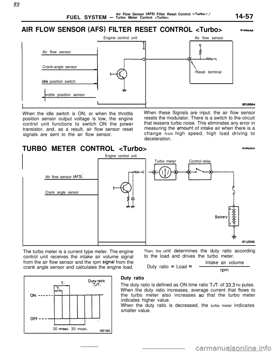
AIR FLOW SENSOR (AFS) FILTER RESET CONTROL
I1Air flow sensor
Crank-angle sensorIdle position switch
Throttle position sensor
4Air flow sensor
//\\ -
\Reset terminal
RllruAs
6FlJo664I11When the idle switch is ON, or when the throttleWhen these Signals are input. the air flow sensor
position sensor output voltage is low, the engineresets the modulator. There is a switch to the circuit
control unit functions to switch ON the powerthat lessens turbo noise. This eliminates any error in
transistor, and, as a result, air flow sensor resetmeasuring the
.amount of intake air when there is a
signals are sent to the air flow sensor.change from high speed, high load driving to
deceleration.
TURBO METER CONTROL
Air flow sensor
(AFSI ’
Crank angle sensorEngine control unit
BT
Rl4QAAATurbo meterControl relay
The turbo meter is a current type meter. The engine
control unit receives the intake air volume signal
from the air flow sensor and the rpm
signal from the
crank angle sensor and calculates the engine load.Then, the unit determines the duty ratio according
to the load and drives the turbo meter.
Intake air volume
Duty ratio
it Load 0:rwDuty ratio
The duty ratio is defined as ON time ratio
TJT, of 33.3 Hz pulse.
When the duty ratio increases, average current that flows to
the turbo meter also increases
so that the turbo meter
indicates higher value.
When the duty ratio is decreased, the turbo meter indicates
smaller value.
cI30
msec. 30 msec.1621cm:
Page 269 of 391
‘4) Once the operation is step (2) is completed, the
hydraulic control device functions by hydraulic
pressure force to change the state of the
clutches and brakes to accomplish the gear
shifting. To minimize the shock that would
otherwise be produced during gear shifting,
hydraulic pressure is controlled during the gear
shifting period by the “duty control” of the
pressure control solenoid valve. The duty control
is explained later.
‘HYDRAULIC PRESSURE CONTROL DURING
SHFIING(1) The hydraulic pressure that functions during
gear shifting to engage the clutches and apply
the brakes is regulated by the pressure control
valve, The hydraulic pressure that works on the
pressure control valve is further regulated by the
pressure control solenoid valve which functions
under the control of the transaxle control unit.
The transaxle control unit controls the solenoid
valve through the duty control, thus providing
appropriate regulation of the hydraulic pressure.
(2)
(3)
(4)The transaxle control unit decides the timing of
the gear shifting period (during which ‘it per-
forms hydraulic pressure control for gear shift-
ing) according to the change in the kickdown
drum rotating speed that it detects. The unit
identifies the time just before the kickdown
brake is applied and uses that as the timing for
initiating control of the hydraulic pressure which
is to be applied to the kickdown brake.
When the transaxle is cold, the fluid viscosity is
high, causing slower oil pressure response. in
such conditions, the transaxle control unit pro-
vides a correction for the oil pressure by
changing the control duty of the pressure control
solenoid valve.
This control is performed when the fluid temper-
atures as indicated by the oil temperature
sensor is lower than
60°C (140°F).After the engine has been started and the
vehicle is inmotion, the transaxle
continues torefine its performance
est possiblegear shifting.control unit
for smooth-
tHFigure B
- Duty(%)
17500661750067
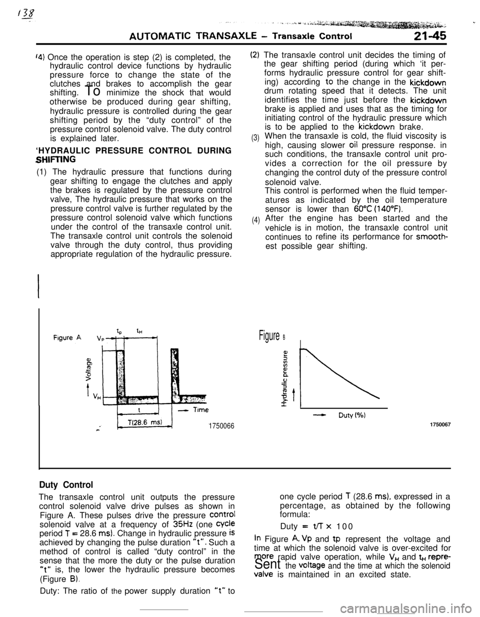
Duty ControlThe transaxle control unit outputs the pressureone cycle period
T (28.6 ms), expressed in a
control solenoid valve drive pulses as shown inpercentage, as obtained by the following
formula:
Figure A. These pulses drive the pressure
COrmIsolenoid valve at a frequency of
35Hz (one Cycleperiod
T = 28.6 ms). Change in hydraulic pressure iSDuty =t/-r x 100
achieved by changing the pulse duration
“t”. Such aIn Figure A, Vp and tp represent the voltage and
method of control is called “duty control” in thetime at which the solenoid valve is over-excited for
sense that the more the duty or the pulse duration
more rapid valve operation, while V,, and t+., repre-
“t” is, the lower the hydraulic pressure becomesSent the v,oltage and the time at which the solenoid(Figure
B).Valve is maintained in an excited state.
Duty: The ratio of the power supply duration
“t” to
Page 291 of 391
/gi--__ .--.-9
Reducingvalve
To kickdown
servo via 1 - 2
shift valveLine pressureAUTOMATIC TRANSAXLE
- Transaxle Control21-69
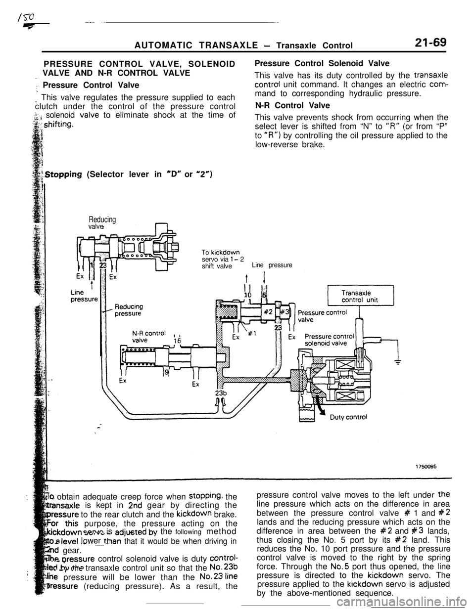
PRESSURE CONTROL VALVE, SOLENOID
-_ VALVE AND N-R CONTROL VALVE
: Pressure Control Valve
: This valve regulates the pressure supplied to each
clutch under the control of the pressure control
j.. solenoid<,A ,valve to eliminate shock at the time ofPressure Control Solenoid Valve
This valve has its duty controlled by the transaxlecontrol unit command. It changes an electric com-
mand to corresponding hydraulic pressure.
N-R Control Valve
This valve prevents shock from occurring when the
select lever is shifted from “N” to
“R” (or from “P”
to
“R”) by controlling the oil pressure applied to the
low-reverse brake..Stopping (Selector lever in
“D” or “2”)
‘r) obtain adequate creep force when stopping, the
is kept in
2nd gear by directing the
to the rear clutch and the kickdown brake.
purpose, the pressure acting on the
=nnm is adjusted by the following method
- .--v.._ _ _ __ --Tan that it would be when driving in
..d gear.
he nrennurecontrol solenoid valve is duty control-
..s,. ..Jtransaxle control unit so that the No.231..a
pressure will be lower than the No.23
fine
bressure (reducing pressure). As a result, the
level lower ttlpressure control valve moves to the left under the
line pressure which acts on the difference in area
between the pressure control valve
# 1 and #2lands and the reducing pressure which acts on the
difference in area between the
#2 and #3 lands,
thus closing the No. 5 port by its
#2 land. This
reduces the No. 10 port pressure and the pressure
control valve is moved to the right by the spring
force. Through the No.5 port thus opened, the line
pressure is directed to the kickdown servo. The
pressure applied to the kickdown servo is adjusted
by the above-mentioned sequence.
-
Page 354 of 391
BODY - Seat Belts23-37COMPONENT PARTS AND FUNCTION
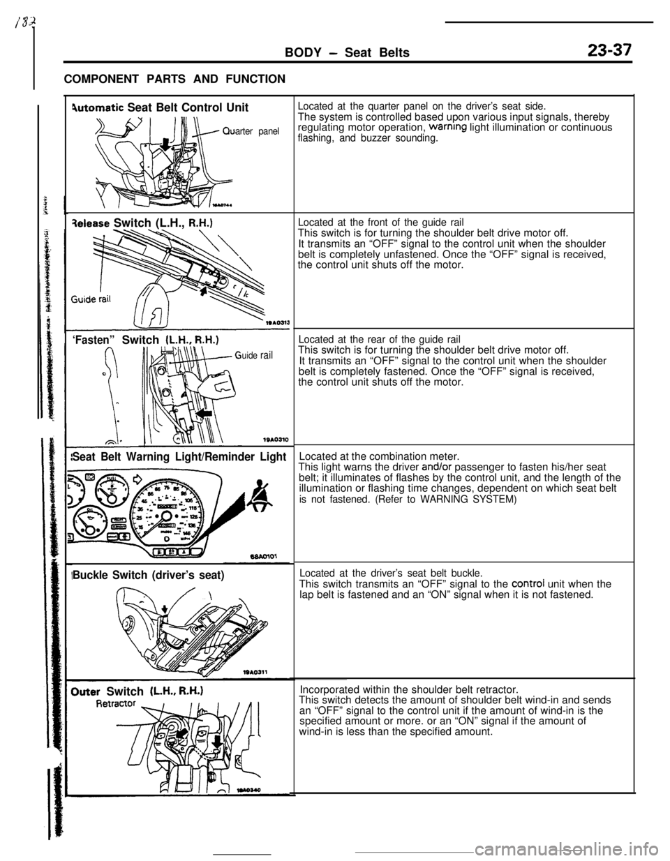
4utomatic Seat Belt Control Unit
arter panel
qelease Switch (L.H., R.H.)
‘Fasten”Switch (L.H., R.H.)
uide rail
1SAO310
Seat Belt Warning Light/Reminder Light
Buckle Switch (driver’s seat)
Outer Switch (LH., R.H.)
Located at the quarter panel on the driver’s seat side.The system is controlled based upon various input signals, thereby
regulating motor operation,
warnrng light illumination or continuousflashing, and buzzer sounding.
Located at the front of the guide railThis switch is for turning the shoulder belt drive motor off.
It transmits an “OFF” signal to the control unit when the shoulder
belt is completely unfastened. Once the “OFF” signal is received,
the control unit shuts off the motor.
Located at the rear of the guide railThis switch is for turning the shoulder belt drive motor off.
It transmits an “OFF” signal to the control unit when the shoulder
belt is completely fastened. Once the “OFF” signal is received,
the control unit shuts off the motor.
Located at the combination meter.
This light warns the driver
and/or passenger to fasten his/her seat
belt; it illuminates of flashes by the control unit, and the length of the
illumination or flashing time changes, dependent on which seat belt
is not fastened. (Refer to WARNING SYSTEM)
Located at the driver’s seat belt buckle.This switch transmits an “OFF” signal to the
control unit when the
lap belt is fastened and an “ON” signal when it is not fastened.
Incorporated within the shoulder belt retractor.
This switch detects the amount of shoulder belt wind-in and sends
an “OFF” signal to the control unit if the amount of wind-in is the
specified amount or more. or an “ON” signal if the amount of
wind-in is less than the specified amount.
Page 360 of 391
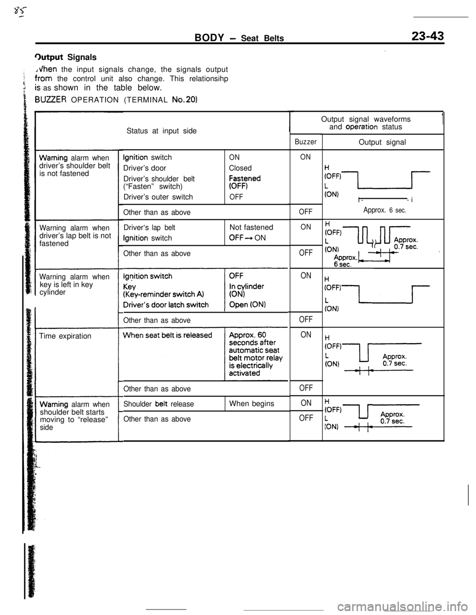
BODY - Seat Belts23-43
9utput SignalsJhen the input signals change, the signals output
rorn the control unit also change. This relationsihp
; as shown in the table below.
IUZZER OPERATION (TERMINAL No.201
Warning alarm whendriver’s shoulder belt
is not fastened
Warning alarm whendriver’s lap belt is not
fastened
Warning alarm whenkey is left in key
cylinder
Time expiration
Warning alarm whenshoulder belt starts
moving to “release”
sideStatus at input sideIgnition switch
Driver’s door
Driver’s
shoulder belt(“Fasten” switch)
Driver’souter switch
Other than as aboveDriver‘s
lap beltIgnition switch
Other than as above
ON
Closed
E-Yned
OFFNot fastenedOFF-+ ON
*
Other than as above
hh
Other than as above
Shoulder beit
release
Other than as aboveWhen beginsOutput signal waveforms
1
Buzzer
ON
OFF
ON
OFF
ON
OFF
ON
OFF
ON
OFFand operation status
Output signal
(ON)I--i
Approx. 6 sec.