change time MITSUBISHI ECLIPSE 1990 Service Manual
[x] Cancel search | Manufacturer: MITSUBISHI, Model Year: 1990, Model line: ECLIPSE, Model: MITSUBISHI ECLIPSE 1990Pages: 391, PDF Size: 15.27 MB
Page 8 of 391
o-4GENERAL - Technical Features
BASIC CONSTRUCTION
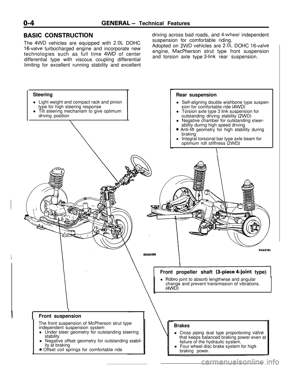
The 4WD vehicles are equipped with
2.OL DOHC
16-valve turbocharged engine and incorporate new
technologies such as full time 4WD of center
differential type with viscous coupling differential
limiting for excellent running stability and excellent
Steering
l Light weight and compact rack and pinion
type for high steering response
l Tilt steering mechanism to give optimum
driving position
\driving across bad roads, and $-wheel independent
suspension for comfortable riding.
Adopted on
2WD vehicles are 2.OL DOHC 16-valveengine, MacPherson strut type front suspension
and torsion axle
typ.e 3-link rear suspension.
Rear suspension
l Self-aligning double wishbone type suspen-
sion for comfortable ride
(4WD)l Torsion axle type 3 link suspension for
outstanding driving stability
(2WD)l Negative chamber for outstanding steer-
ability during high speed driving
0 Anti-lift geometry for high stability duringbraking
lIntegral torsional bar type axle beam for
optimum roll stiffness (2WD)
\Front propeller shaft (3-piece
4-joint type)
lRobro joint to absorb lengthwise and angular
change and prevent transmission of vibrations.
(4WD)
IFront suspension
The front suspension of McPherson strut type
independent suspension system
l Under steer geometry for outstanding steering
stability
l Negative offset geometry for outstanding
stabil-ity at braking
0 Offset coil springs for comfortable ride
Brakes
l Cross piping dual type proportioning valvethat keeps balanced braking power even at
failure of the hydraulic system.
l Four wheel disc brake system for high
braking power.
Page 70 of 391
8-18ELECTRICAL - Lighting
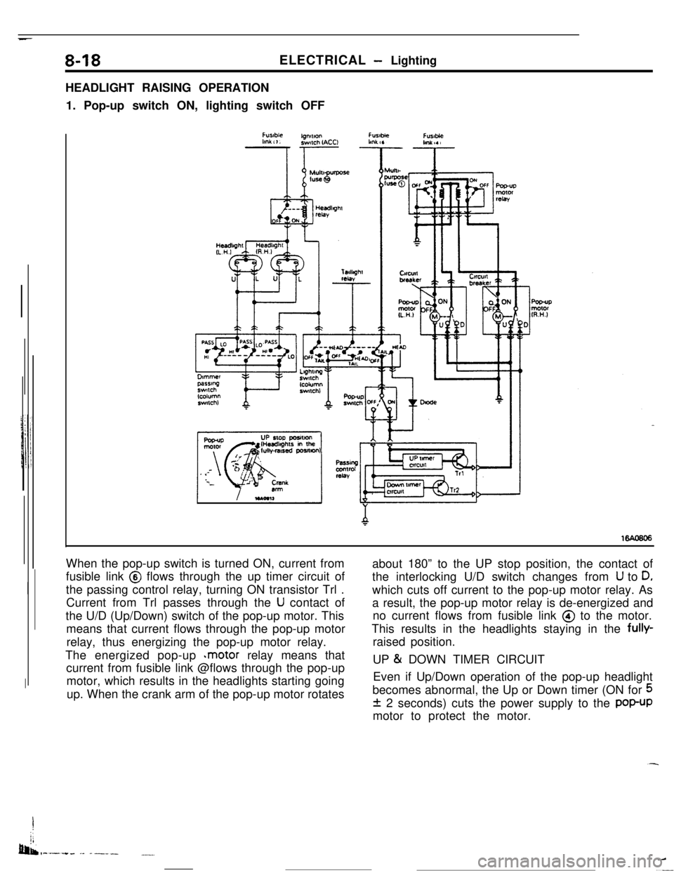
HEADLIGHT RAISING OPERATION
1. Pop-up switch ON, lighting switch OFF
When the pop-up switch is turned ON, current from
fusible link @ flows through the up timer circuit of
the passing control relay, turning ON transistor Trl .
Current from Trl passes through the
U contact of
the U/D (Up/Down) switch of the pop-up motor. This
means that current flows through the pop-up motor
relay, thus energizing the pop-up motor relay.
The energized pop-up
*motor relay means that
current from fusible link @flows through the pop-up
motor, which results in the headlights starting going
up. When the crank arm of the pop-up motor rotatesabout 180” to the UP stop position, the contact of
the interlocking U/D switch changes from
U to D,which cuts off current to the pop-up motor relay. As
a result, the pop-up motor relay is de-energized and
no current flows from fusible link @ to the motor.
This results in the headlights staying in the fully-
raised position.
UP
& DOWN TIMER CIRCUIT
Even if Up/Down operation of the pop-up headlight
becomes abnormal, the Up or Down timer (ON for
5
f 2 seconds) cuts the power supply to the POP-UPmotor to protect the motor.
I
jj
bib,-.-.+. -- ------.__
Page 72 of 391
_ -. _ -.__-ELECTRICAL
- Lighting
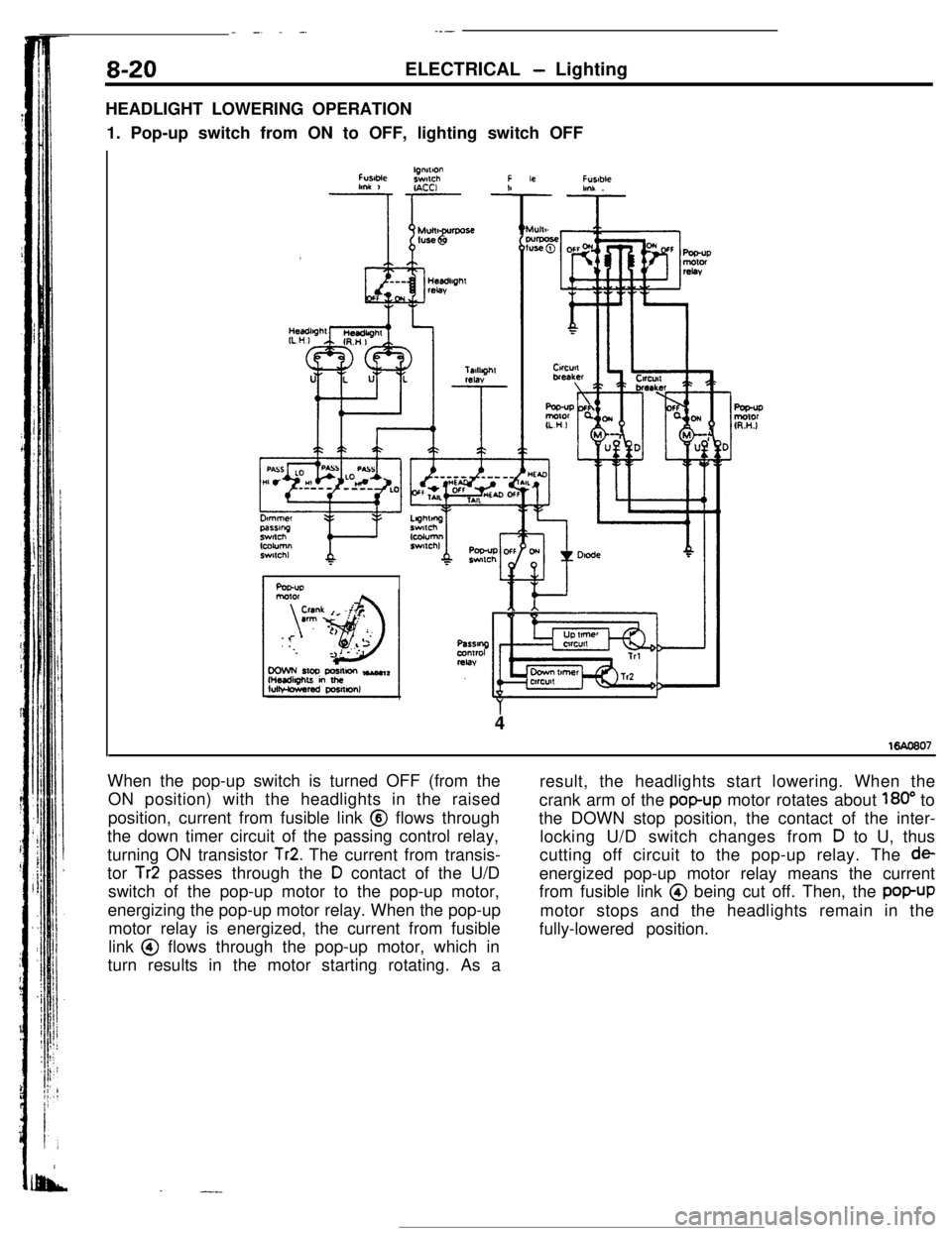
HEADLIGHT LOWERING OPERATION
1. Pop-up switch from ON to OFF, lighting switch OFF
FUslMelgnnlonswlchFlmk 1r- -!IACCI
Ar
Fusablehnk .
4
When the pop-up switch is turned OFF (from the
ON position) with the headlights in the raised
position, current from fusible link @ flows through
the down timer circuit of the passing control relay,
turning ON transistor
Tr2. The current from transis-
tor
Tr2 passes through the D contact of the U/D
switch of the pop-up motor to the pop-up motor,
energizing the pop-up motor relay. When the pop-up
motor relay is energized, the current from fusible
link @ flows through the pop-up motor, which in
turn results in the motor starting rotating. As a
.-.-result, the headlights start lowering. When the
crank arm of the
popup motor rotates about 180” to
the DOWN stop position, the contact of the inter-
locking U/D switch changes from
D to U, thus
cutting off circuit to the pop-up relay. The
deenergized pop-up motor relay means the current
from fusible link @ being cut off. Then, the
popUPmotor stops and the headlights remain in the
fully-lowered position.
Page 83 of 391
Knocking Control for Turbo Engine OnlyEngine coolant tern.Advance mapperarure correctton
value- Barometric pressurecorrectton
DelonaIlon
sensorI
lgnmon codKnockmg correcllonprimary currenr
v
Knock wbral+onKnockmg LevelDelay anglelgnmon tlmtngdetemon- delermonmon - calculallon - derermmatlon
II
Y
FatlureIdeIeclton
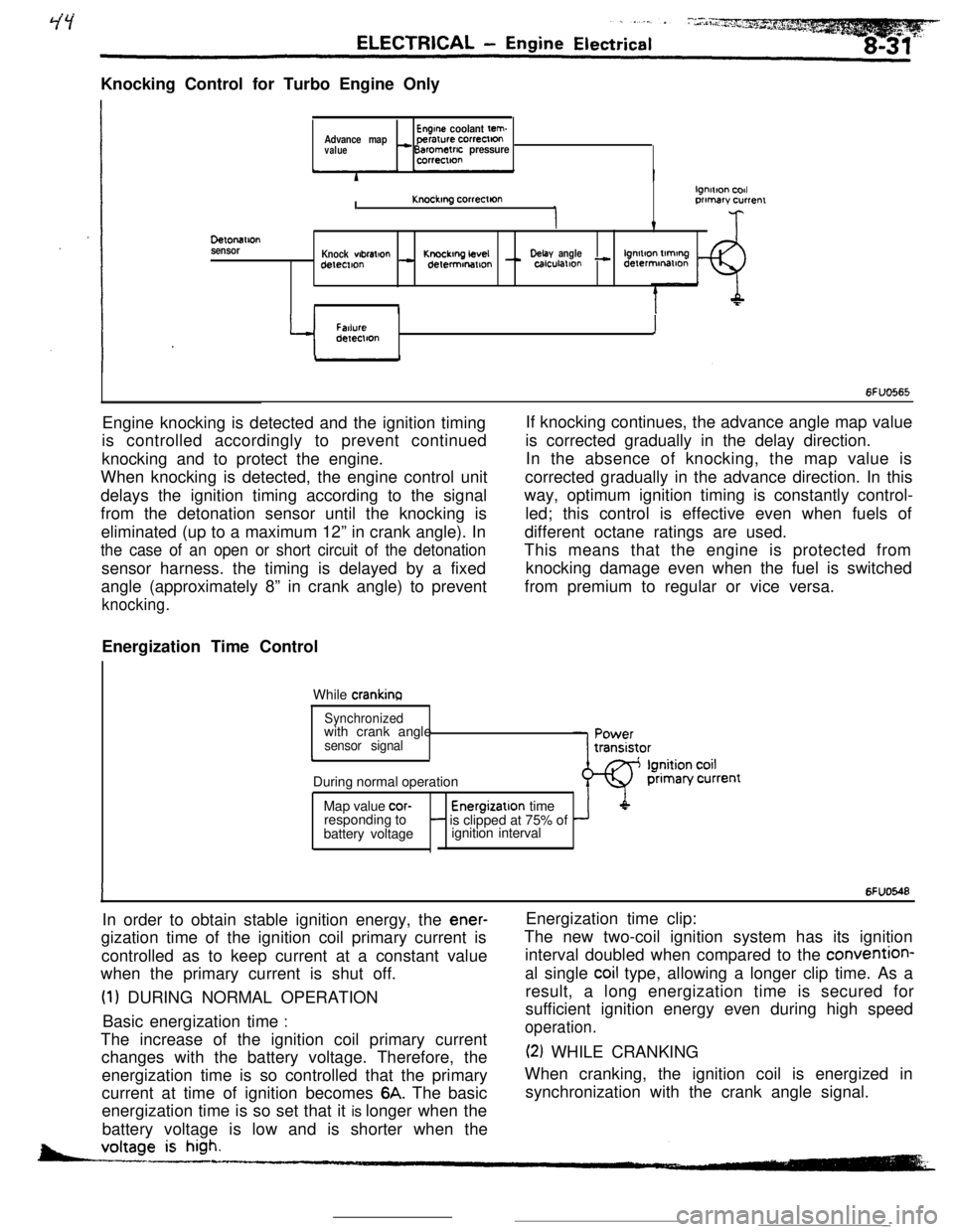
6FUO565Engine knocking is detected and the ignition timing
is controlled accordingly to prevent continued
knocking and to protect the engine.
When knocking is detected, the engine control unit
delays the ignition timing according to the signal
from the detonation sensor until the knocking is
eliminated (up to a maximum 12” in crank angle). In
the case of an open or short circuit of the detonationsensor harness. the timing is delayed by a fixed
angle (approximately 8” in crank angle) to prevent
knocking.Energization Time Control
While
crankinaIf knocking continues, the advance angle map value
is corrected gradually in the delay direction.
In the absence of knocking, the map value is
corrected gradually in the advance direction. In this
way, optimum ignition timing is constantly control-
led; this control is effective even when fuels of
different octane ratings are used.
This means that the engine is protected from
knocking damage even when the fuel is switched
from premium to regular or vice versa.
Synchronizedwith crank angle
sensor signalcDuring normal operation
Map value
cor-Energizatlon time
responding to- is clipped at 75% of
battery voltageignition interval
IIn order to obtain stable ignition energy, the
ener-gization time of the ignition coil primary current is
controlled as to keep current at a constant value
when the primary current is shut off.
(1) DURING NORMAL OPERATION
Basic energization time
:The increase of the ignition coil primary current
changes with the battery voltage. Therefore, the
energization time is so controlled that the primary
current at time of ignition becomes
6A. The basic
energization time is so set that it is longer when the
battery voltage is low and is shorter when the
6FUO548Energization time clip:
The new two-coil ignition system has its ignition
interval doubled when compared to the convention-
al single
coil type, allowing a longer clip time. As a
result, a long energization time is secured for
sufficient ignition energy even during high speed
operation.
(2) WHILE CRANKING
When cranking, the ignition coil is energized in
synchronization with the crank angle signal.
-
Page 128 of 391
14-16FUEL SYSTEM - Sensors
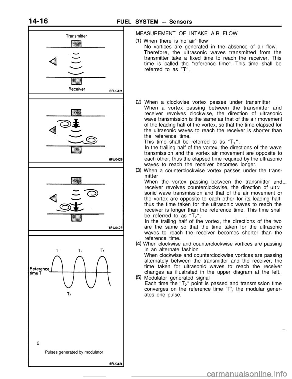
TransmitterMEASUREMENT OF INTAKE AIR FLOW
(1) When there is no air’ flow
No vortices are generated in the absence of air flow.
Therefore, the ultrasonic waves transmitted from the
transmitter take a fixed time to reach the receiver. This
time is called the “reference time”. This time shall be
referred to as
“T”.
Recetver6FUo42!
6FUO426
6f UO42;
TIT1Tl
~tee;ence
9%
T22
Pulses generated by modulator
(2) When a clockwise vortex passes under transmitter
When a vortex passing between the transmitter and
receiver revolves clockwise, the direction of ultrasonic
wave transmission is the same as that of the air movement
of the leading half of the vortex, so that the time elapsed for
the ultrasonic waves to reach the receiver is shorter than
the reference time.
This time shall be referred to as
“T, “.
In the trailing half of the vortex, the directions of the wave
transmission and the vortex air movement are opposite to
each other, thus the elapsed time required by the ultrasonic
waves to reach the receiver becomes longer.
(3) When a counterclockwise vortex passes under the trans-
mitter
When the vortex passing between the transmitter
and-.receiver revolves counterclockwise, the direction of ultr:
sonic wave transmission and that of the air movement
OTthe vortex are opposite to each other for its leading half,
thus the time taken for the ultrasonic waves to reach the
receiver is longer than the reference time. This time shall
be referred to as
“Tz”.In the trailing half of the vortex, the directions of the two
are the same so that the time taken for the ultrasonic
waves to reach the receiver becomes shorter than the
reference time.
(4) When clockwise and counterclockwise vortices are passing
in an alternate fashion
When clockwise and counterclockwise vortices are passing
alternately between the transmitter and the receiver, the
time taken for ultrasonic waves to reach the receiver
changes as illustrated in the upper diagram at the left.
(5) Modulator generated signal
Each time the “T2” point is passed and transmission time
converges on the reference time “T”, the modular gener-
ates one pulse.
-
Page 133 of 391
FUEL SYSTEM - Sensors14-21When exposed to light, the photo diode conducts
urrent in a direction opposite to an ordinary diode.
.s a result, current flows in the direction indicated
by the arrow and dotted line and a voltage (5 volts) isapplied to the comparator of the sensor unit so that
the terminal voltage of the engine control unit
becomes 5 volts. When the disc rotates further andthe slit moves beyond the space between the
LED/photo diode pair, the light can no longer reach
the photo diode, thus the current indicated by the
dotted line ceases to flow and the terminal voltage
of the engine control unit becomes 0 volt.
tn this
way, pulse signals are sent to the engine control
unit from the sensor unit.
OXYGEN SENSOR
k
1 ~~~~t13ate~ousingCoverLead wiresConnectorHeater
Enginecontrol unit6FUlOO5
- Oxygen‘-serisor
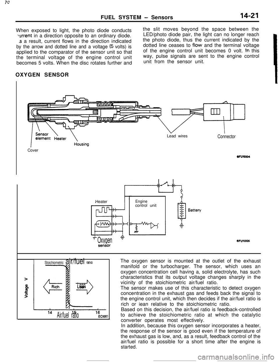
The oxygen sensor is mounted at the outlet of the exhaust
manifold or the turbocharger. The sensor, which uses an
oxygen concentration cell having a, solid electrolyte, has such
characteristics that its output voltage changes sharply in the
vicinity of the stoichiometric air/fuel ratio.
The sensor makes use of this characteristic to detect oxygen
concentration in the exhaust gas and feeds back the signal to
the engine control unit, which then decides if the air/fuel ratio is
rich or iean relative to the stoichiometric ratio.
Based on this decision, the air/fuel ratio is feedback-controlled
to achieve the stoichiometric ratio at which the catalytic
converter operates most effectively.
In addition, because this oxygen sensor incorporates a heater,
the response of the sensor is good even if the temperature of
the exhaust gas is low, and, as a result, feedback control of the
air/fuel ratio is possible for a short time after the engine is
started.
Stoichiometric air/fuel ratlo
r3
Lean
Air/fuel ratioEC1007
Page 153 of 391
FUEL SYSTEM -Fuel Injection Control
14-41
During normal operation (including idling), the en-
gine control unit controls the injector activation time
tcThieve the stoichiometric air/fuel ratio, which
e.;res maximum efficiency of the catalytic conver-
ter, on the basis of the oxygen sensor signal.
When the air/fuel mixture is richer than the
stoichiometric ratio, there is less oxygen in the
exhaust gas and thus the oxygen sensor output
voltage is higher; hence a “mixture rich” signal is
input to the engine control unit. Then, the engine
control unit decreases the amount of fuel injected. If
the air/fuel ratio decreases to the point that and the
mixture becomes leaner than the stoichiometric
ratio, the oxygen concentration in the exhaust gas
increases and the oxygen sensor output voltage
becomes lower. Then, a “mixture lean” signal isinput to the engine control unit.
Upon input of this signal, the engine control unit
increases the feedback correction factor, thus caus-
ing more fuel to be injected.
By means of the above-mentioned controls (collec-
tively called “feedback control”), the air-fuel mixture
is maintained at the stoichiometric ratio.
Under the following specific conditions, this feed-
back control is not performed, in order to improve
driveability.
(11
(2)
::I
(5)While cranking the engine
During engine warm-up when engine coolant
temperature is less than
45°C (113°F)During acceleration/deceleration
During high load operation
When oxygen sensor is not functioning
IOPEN LOOP CONTROL
Engine speed rpm6FUO274
II
80(176)
Coolant temperature “C (“Fj6FlJO276
I425(77)
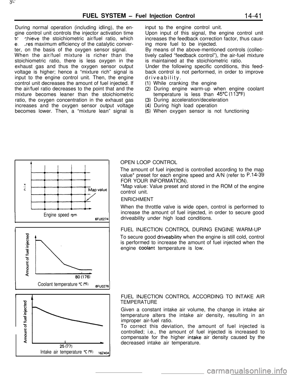
Intake air temperature “C (“F)1~40,0IThe amount of fuel injected is controlled according to the map
value* preset for each engine speed and A/N (refer to
P.l4-39FOR YOUR INFORMATION).
*Map value: Value preset and stored in the ROM of the engine
control unit.
ENRICHMENTWhen the throttle valve is wide open, control is performed to
increase the amount of fuel injected, in order to secure good
driveability under high load conditions.
FUEL INJECTION CONTROL DURING ENGINE WARM-UP
To secure good driveability when the engine is still cold, control
is performed to increase the amount of fuel injected when the
engine
cooiant temperature is low.
FUEL INJECTION CONTROL ACCORDING TO INTAKE AIR
TEMPERATUREGiven a constant intake air volume, the change in intake air
temperature alters the intake air density, resulting in an
improper air-fuel ratio.
To correct this deviation, the amount of fuel injected is
controlled; i.e., the amount of fuel injected is increased to
compensate for the higher
intake air density caused by the
decreased intake air temperature.
Page 154 of 391
14-42
FUEL SYSTEM- Fuel Injection Control
4
Fz.or.c
4:0/
E
{!*760 (301Barometric pressure
mmHg (in.Hg) 6Fuo9z
c
Timet
6FUO279Drivecurrent
0: bri
F2JJ’ ipe; II
I+-JValve opening timi16240:
E‘C
F
.-
is
3
3:\Battery voltage
V162406
80 (176)Coolant temperature
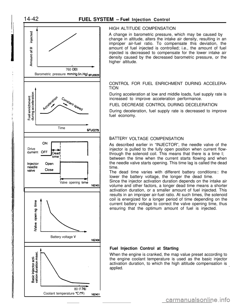
“C (“F)162401HIGH ALTITUDE COMPENSATION
A change in barometric pressure, which may be caused by
change in altitude, alters the intake air density, resulting in an
improper air-fuel ratio. To compensate this deviation, the
amount of fuel injected is controlled; i.e., the amount of fuel
injected is decreased to compensate for the lower intake air
density caused by the decreased barometric pressure, or the
higher altitude.
CONTROL FOR FUEL ENRICHMENT DURING ACCELERA-
TIONDuring acceleration at low and middle loads, fuel supply rate is
increased to improve acceleration performance.
FUEL DECREASE CONTROL DURING DECELERATION
During deceleration, fuel supply rate is decreased to improve
fuel economy.
BATTERY VOLTAGE COMPENSATION
As described earlier in “INJECTOR”, the needle valve of the
injector is pulled to the fully open position when current flow-
through the solenoid coil. This means that there is a time I;
between the time when the current starts flowing and when
the needle valve starts opening. This time lag is called the dead
time.
The dead time varies with different battery conditions:: the
lower the battery voltage, the longer the dead time.
Since the injector activation duration depends on the intake air
volume and other factors, a longer dead time means a shorter
activation duration, or a smaller amount of fuel injected. This
results in an improper air-fuel ratio. At such times, the solenoid
coil is energized for a longer period of time depending on the
current battery voltage to correct the valve opening time, thus
ensuring that the optimum amount of fuel is injected.
Fuel Injection Control at Starting
When the engine is cranked, the map value preset according to
the engine coolant temperature is used as the basic injector
activation duration, to which the high altitude compensation is
applied..
Page 155 of 391
FUEL SYSTEM - Fuel Injection Control14-43
Time
6FUO26
Engine has started.
El.-*STime ’6fFuel Injection Control during Acceleration
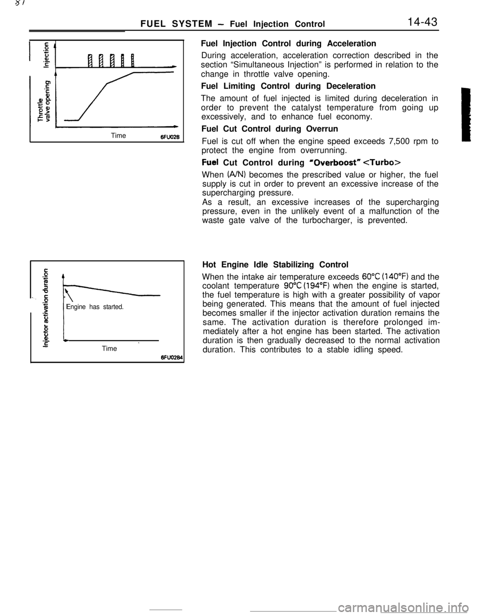
During acceleration, acceleration correction described in the
section “Simultaneous Injection” is performed in relation to the
change in throttle valve opening.
Fuel Limiting Control during Deceleration
The amount of fuel injected is limited during deceleration in
order to prevent the catalyst temperature from going up
excessively, and to enhance fuel economy.
Fuel Cut Control during Overrun
Fuel is cut off when the engine speed exceeds 7,500 rpm to
protect the engine from overrunning.
Fuel Cut Control during ‘Overboost”
(A/N) becomes the prescribed value or higher, the fuel
supply is cut in order to prevent an excessive increase of the
supercharging pressure.
As a result, an excessive increases of the supercharging
pressure, even in the unlikely event of a malfunction of the
waste gate valve of the turbocharger, is prevented.
Hot Engine Idle Stabilizing Control
When the intake air temperature exceeds
60°C (140°F) and the
coolant temperature
90°C (194°F) when the engine is started,
the fuel temperature is high with a greater possibility of vapor
being generated. This means that the amount of fuel injected
becomes smaller if the injector activation duration remains the
same. The activation duration is therefore prolonged im-
mediately after a hot engine has been started. The activation
duration is then gradually decreased to the normal activation
duration. This contributes to a stable idling speed.
Page 161 of 391
FUEL SYSTEM -Idle Speed Control14-49
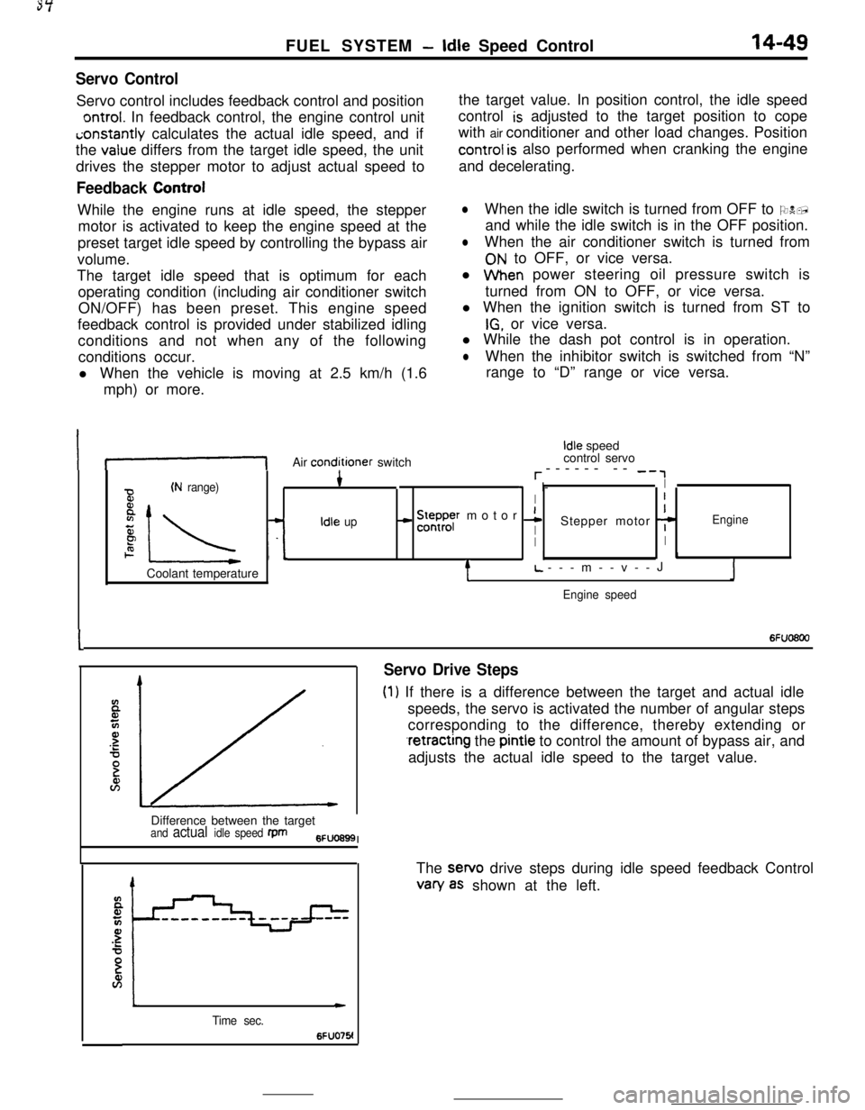
Servo ControlServo control includes feedback control and position
ontrol. In feedback control, the engine control uniti;onstantly calculates the actual idle speed, and if
the
value differs from the target idle speed, the unit
drives the stepper motor to adjust actual speed to
Feedback ControlWhile the engine runs at idle speed, the stepper
motor is activated to keep the engine speed at the
preset target idle speed by controlling the bypass air
volume.
The target idle speed that is optimum for each
operating condition (including air conditioner switch
ON/OFF) has been preset. This engine speed
feedback control is provided under stabilized idling
conditions and not when any of the following
conditions occur.
l When the vehicle is moving at 2.5 km/h (1.6
mph) or more.the target value. In position control, the idle speed
control
is adjusted to the target position to cope
with air conditioner and other load changes. Position
control is also performed when cranking the engine
and decelerating.
lWhen the idle switch is turned from OFF to ON,
and while the idle switch is in the OFF position.
lWhen the air conditioner switch is turned from
ON to OFF, or vice versa.
l When power steering oil pressure switch is
turned from ON to OFF, or vice versa.
l When the ignition switch is turned from ST to
IG, or vice versa.
l While the dash pot control is in operation.
lWhen the inhibitor switch is switched from “N”
range to “D” range or vice versa.
If-1Air conditioner switch
Idle speed
control servo
r------ -- -‘,
(N range)4* I-I
BI
8
IL -L
- !5ysr motor 1I
zIdle upIStepper motor 7Engine
PII2. I.1Coolant temperature
tL.---m--v--JJ
Engine speed
I6Fuo6oo
Servo Drive Steps
(1) If there is a difference between the target and actual idle
speeds, the servo is activated the number of angular steps
corresponding to the difference, thereby extending or
.retracting the pintle to control the amount of bypass air, and
adjusts the actual idle speed to the target value.
Difference between the target
and actual idle speed fpm6FUO699I
Time sec.
c
6FUO76!The sewo drive steps during idle speed feedback Control
van/ as shown at the left.