suspension MITSUBISHI ECLIPSE 1990 User Guide
[x] Cancel search | Manufacturer: MITSUBISHI, Model Year: 1990, Model line: ECLIPSE, Model: MITSUBISHI ECLIPSE 1990Pages: 391, PDF Size: 15.27 MB
Page 29 of 391
-.-...- ..v:T
3-2REAR AXLE- General Information
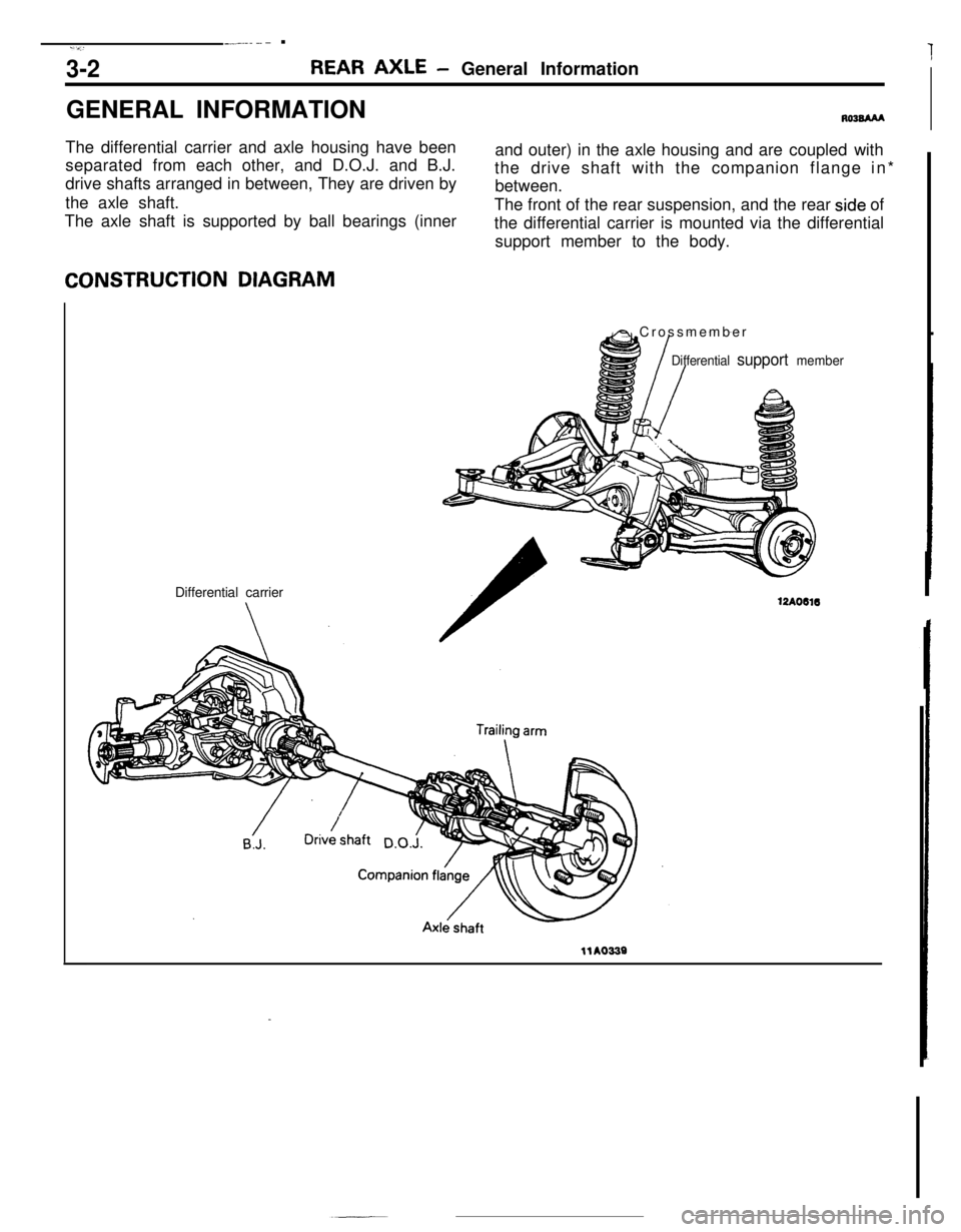
GENERAL INFORMATION
RO3BAAAThe differential carrier and axle housing have been
separated from each other, and D.O.J. and B.J.
drive shafts arranged in between, They are driven by
the axle shaft.
The axle shaft is supported by ball bearings (innerand outer) in the axle housing and are coupled with
the drive shaft with the companion flange in*
between.
The front of the rear suspension, and the rear
side of
the differential carrier is mounted via the differential
support member to the body.CONSTRUCTION DIAGRAM
Differential carrier
A Crossmember
Differential support member
12AO616
llA0339
Page 31 of 391
3-4REAR AXLE - Axle Shaft / Drive Shaft
AXLE SHAFT
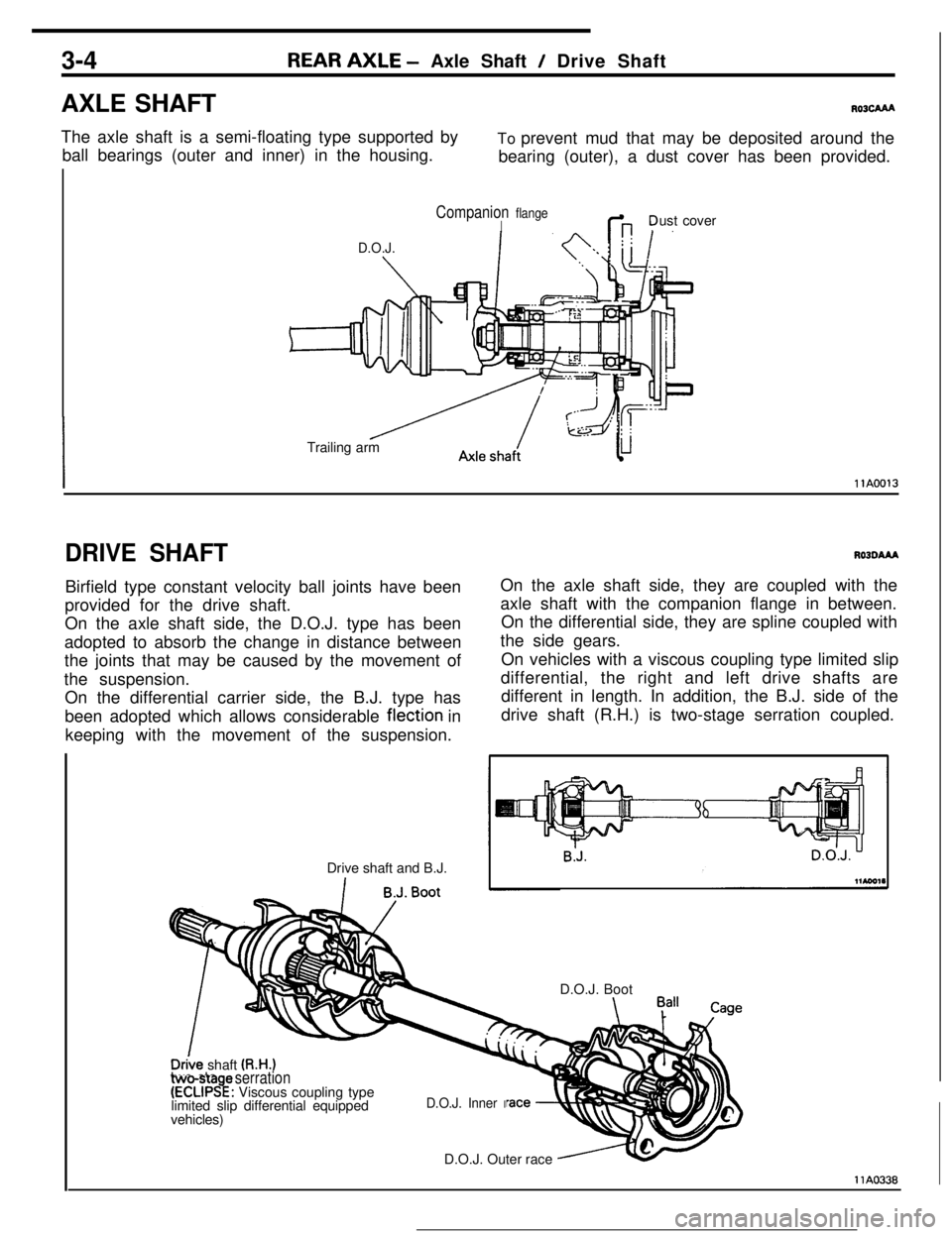
R03cAAAThe axle shaft is a semi-floating type supported by
ball bearings (outer and inner) in the housing.To prevent mud that may be deposited around the
bearing (outer), a dust cover has been provided.
D.O.J.
Companion flangeIG ?ust cover
Trailing arm
IllA0013
DRIVE SHAFTBirfield type constant velocity ball joints have been
provided for the drive shaft.
On the axle shaft side, the D.O.J. type has been
adopted to absorb the change in distance between
the joints that may be caused by the movement of
the suspension.
On the differential carrier side, the B.J. type has
been adopted which allows considerable flection in
keeping with the movement of the suspension.
Drive shaft and B.J.RO3OAAAOn the axle shaft side, they are coupled with the
axle shaft with the companion flange in between.
On the differential side, they are spline coupled with
the side gears.
On vehicles with a viscous coupling type limited slip
differential, the right and left drive shafts are
different in length. In addition, the B.J. side of the
drive shaft (R.H.) is two-stage serration coupled.
D.O.J. Boot
_vehicles)
D.O.J. Outer race
D&e shaft (R.H.)two-sta e serration(ECLIPS!: Viscous coupling type
limited slip differential equipped
D.O.J. Inner I
llA0338
Page 197 of 391
- ._ ____.-.-- -.._ -.-.- - ..__-
17-4 REAR SUSPENSION tZWD>- Wheel Alignment / Anti-lift Geometry
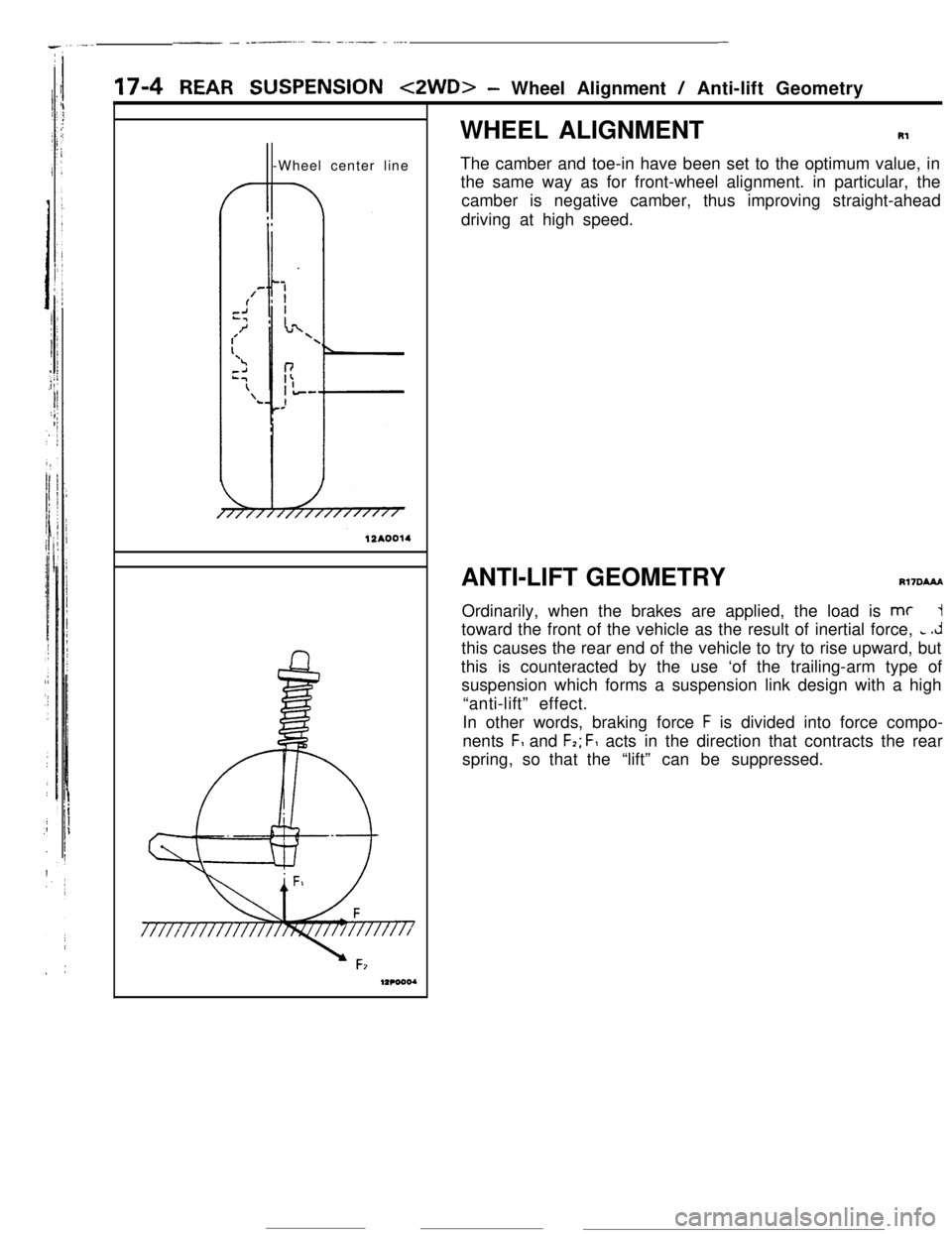
-Wheel center lineWHEEL ALIGNMENTRl
The camber and toe-in have been set to the optimum value, in
the same way as for front-wheel alignment. in particular, the
camber is negative camber, thus improving straight-ahead
driving at high speed.
ANTI-LIFT GEOMETRY
Rl7DAAAOrdinarily, when the brakes are applied, the load is
mc1toward the front of the vehicle as the result of inertial force,
c .Jthis causes the rear end of the vehicle to try to rise upward, but
this is counteracted by the use ‘of the trailing-arm type of
suspension which forms a suspension link design with a high
“anti-lift” effect.
In other words, braking force
F is divided into force compo-
nents
F, and F,; F, acts in the direction that contracts the rear
spring, so that the“lift” can be suppressed.
Page 198 of 391
---_REAR SUSPENSION
<2WD> - Three-link Suspension17-5
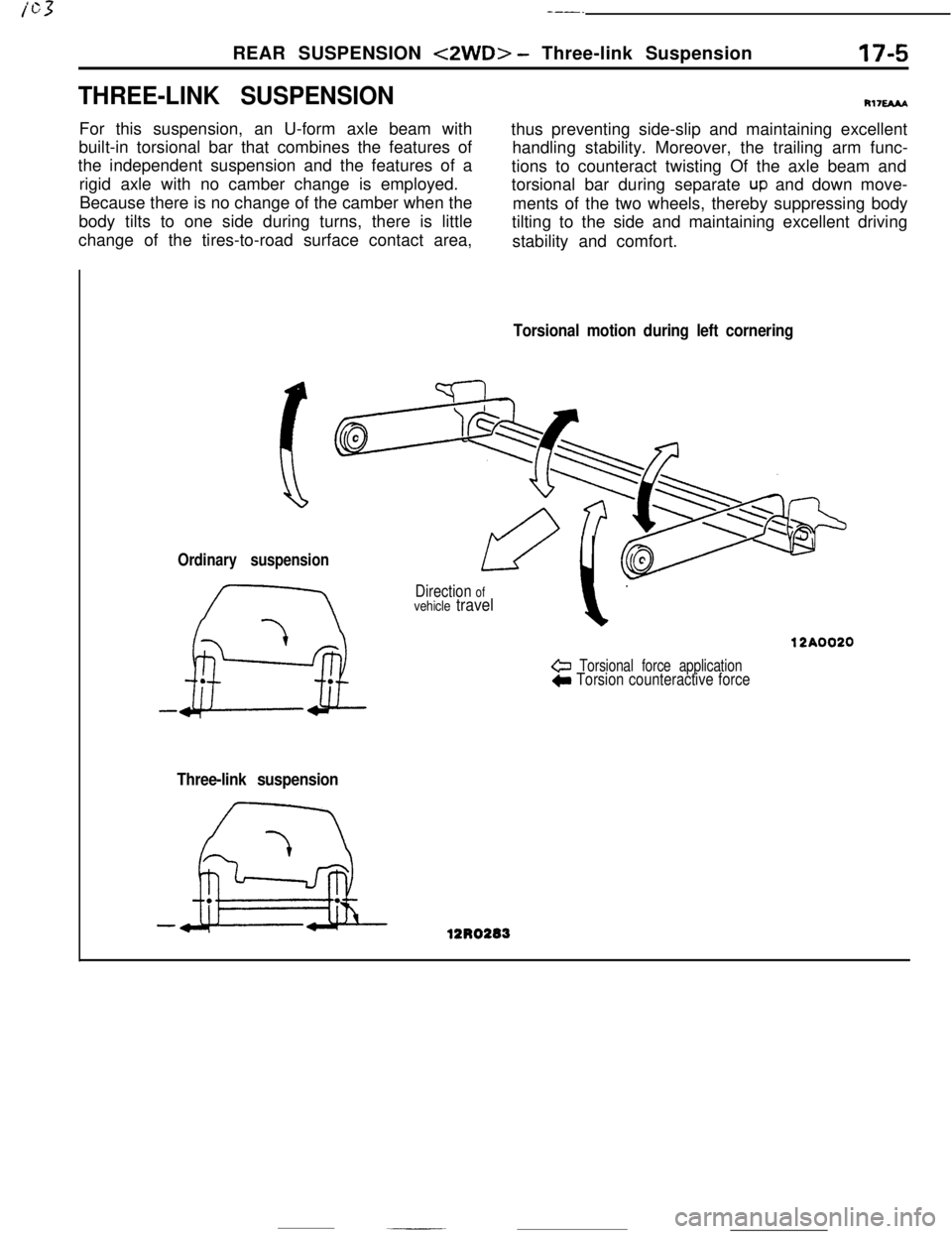
THREE-LINK SUSPENSIONFor this suspension, an U-form axle beam with
built-in torsional bar that combines the features of
the independent suspension and the features of a
rigid axle with no camber change is employed.
Because there is no change of the camber when the
body tilts to one side during turns, there is little
change of the tires-to-road surface contact area,
R1naAAthus preventing side-slip and maintaining excellent
handling stability. Moreover, the trailing arm func-
tions to counteract twisting Of the axle beam and
torsional bar during separate
UP and down move-
ments of the two wheels, thereby suppressing body
tilting to the side and maintaining excellent driving
stability and comfort.
Torsional motion during left cornering
Ordinary suspension
Direction ofvehicle travel
& Torsional force applicationC Torsion counteractive force
Three-link suspension
Page 199 of 391
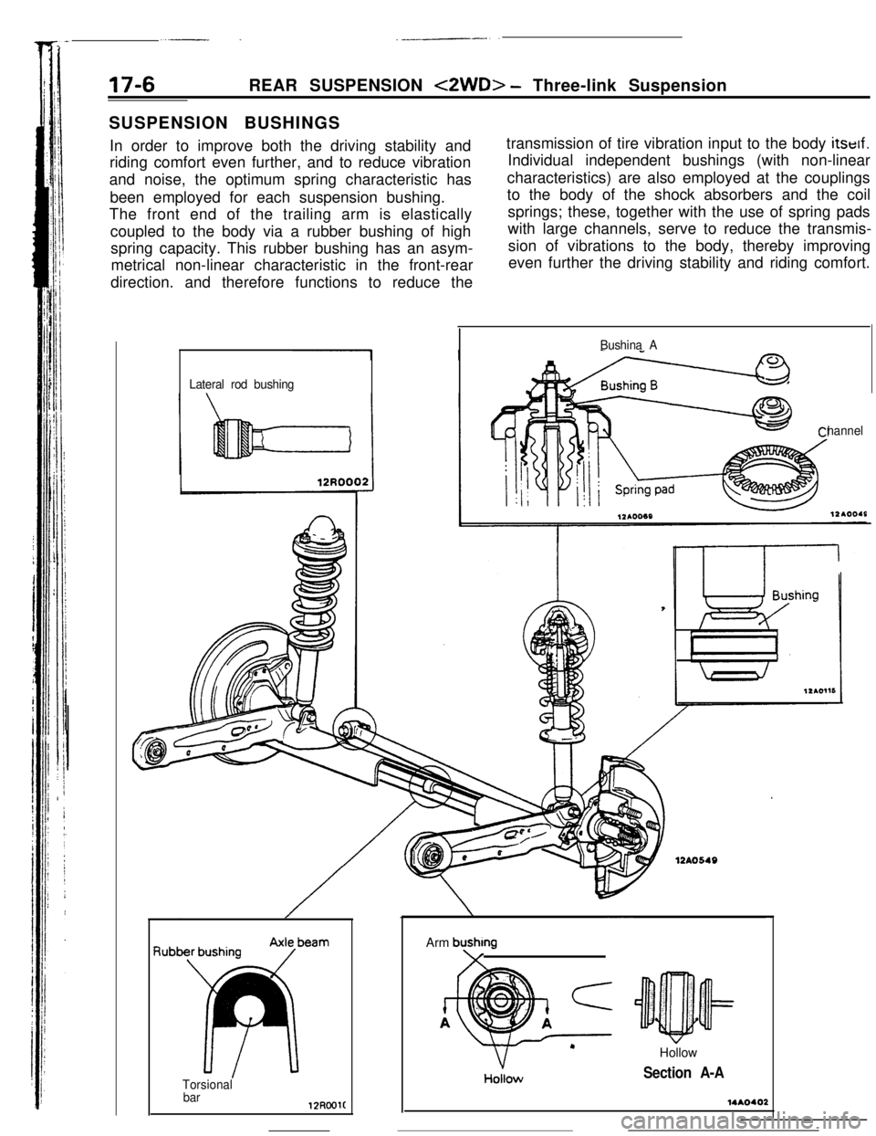
17-6REAR SUSPENSION <2WD> - Three-link Suspension
SUSPENSION BUSHINGS
In order to improve both the driving stability and
riding comfort even further, and to reduce vibration
and noise, the optimum spring characteristic has
been employed for each suspension bushing.
The front end of the trailing arm is elastically
coupled to the body via a rubber bushing of high
spring capacity. This rubber bushing has an asym-
metrical non-linear characteristic in the front-rear
direction. and therefore functions to reduce thetransmission of tire vibration input to the body itself.
Individual independent bushings (with non-linear
characteristics) are also employed at the couplings
to the body of the shock absorbers and the coil
springs; these, together with the use of spring pads
with large channels, serve to reduce the transmis-
sion of vibrations to the body, thereby improving
even further the driving stability and riding comfort.
Lateral rod bushingBushina A
hannel
f3ub
Torsional
barArm
bushmg\/HollowHoilow
Section A-A
Page 200 of 391
/cY
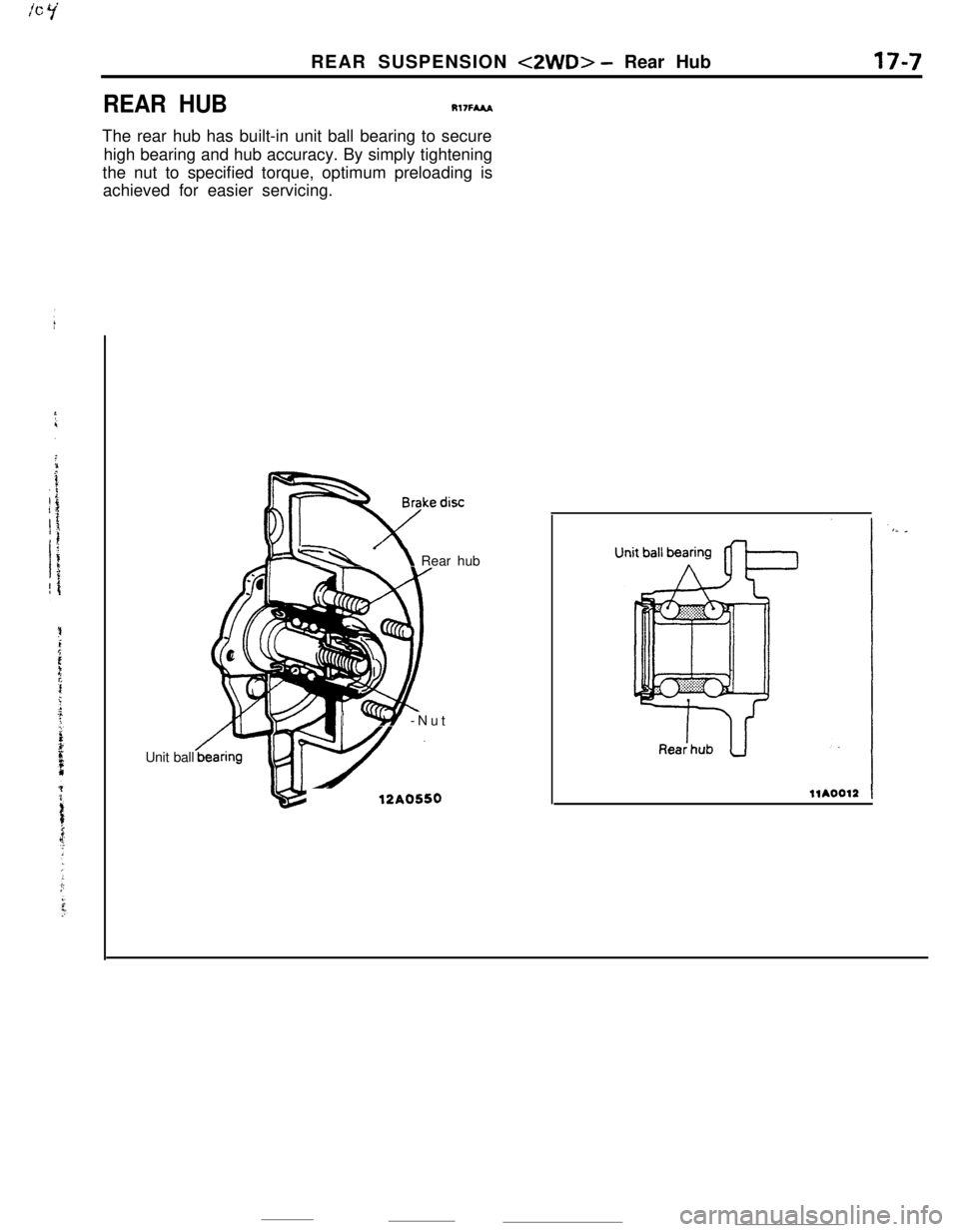
REAR HUBREAR SUSPENSION
<2WD> - Rear Hub
Rl7FMA
17-7The rear hub has built-in unit ball bearing to secure
high bearing and hub accuracy. By simply tightening
the nut to specified torque, optimum preloading is
achieved for easier servicing.
Unit ball
a -\ Rear hub
/‘YLLY -Nut
12A0550
Page 201 of 391
.-_. -
17-8REAR SUSPENSION <4WD> - Geneal information
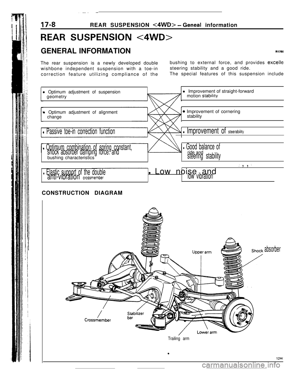
REAR SUSPENSION <4WD>GENERAL INFORMATION
Rl7BEThe rear suspension is a newly developed double
wishbone independent suspension with a toe-in
correction feature utilizing compliance of thebushing to external force, and provides
excellesteering stability and a good ride.
The special features of this suspension include
l Optimum adjustment of suspensiongeometry
l Optimum adjustment of alignment
change
0 Passive toe-in correction function
l Optimum combination of spring constant,
shock absorber damping force. andbushing characteristics
l Elastic support of the doubleanti-vibration croSsmemberl Improvement of straight-forward
motion stability
0 Improvement of cornering
stability
l Improvement of steerability
l Good balance ofride andsteering stability
( , , :l Low noise and
low vibrationCONSTRUCTION DIAGRAM
absorber
Trailing arm
.
12AC
Page 202 of 391
_ -. ..__ .-
REAR SUSPENSION
<4WD> - Geneal (nformation
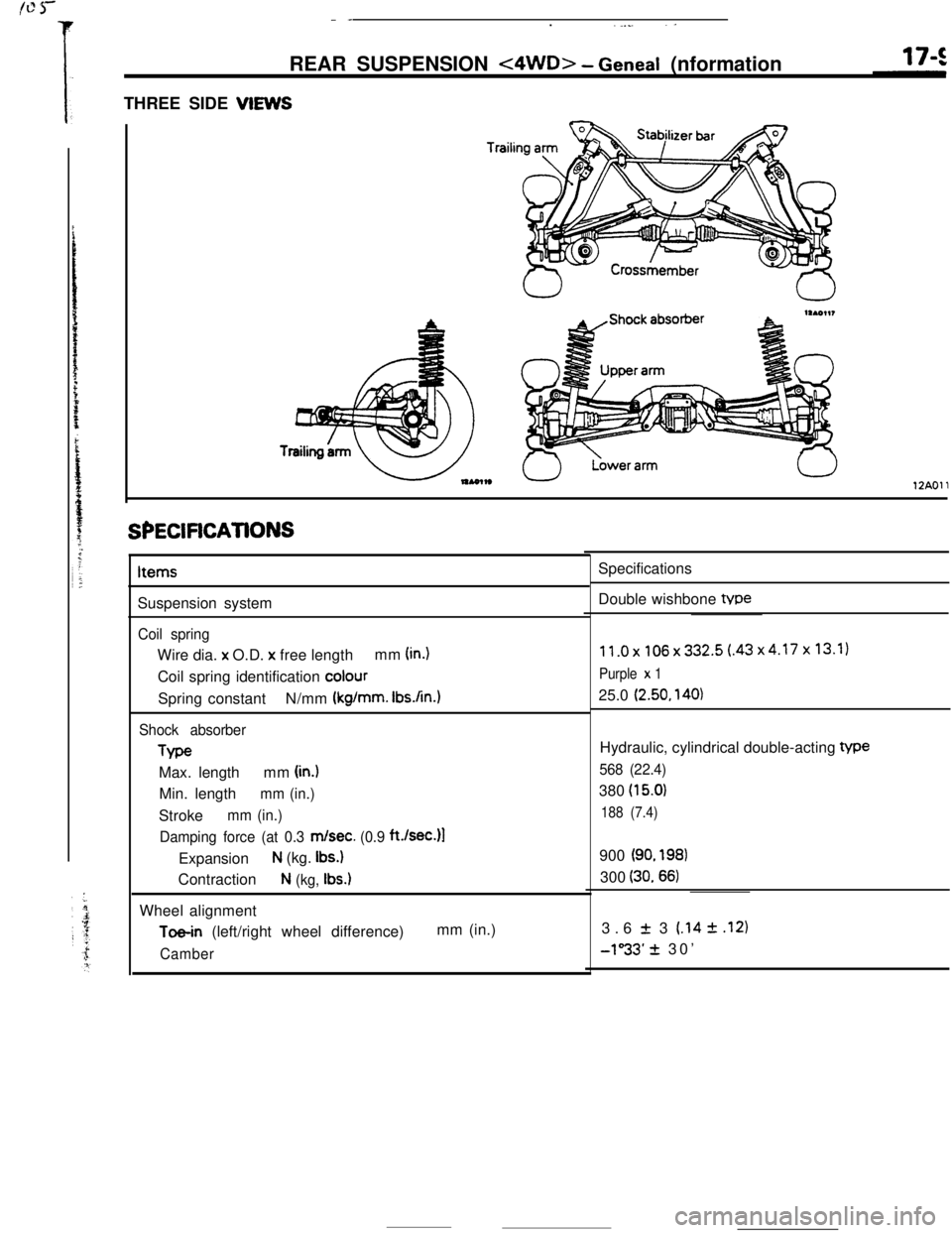
THREE SIDE VIEWS
Trailil
12AOll
SPECiFiCATiONSItems
Suspension system
Coil springWire dia. x O.D.
x free lengthmm (in.)Coil spring identification
colourSpring constantN/mm
(kg/mm. Ibs.An.1
Shock absorberType
Max. lengthmm
(in.)Min. length
mm (in.)Stroke
mm (in.)
Damping force (at 0.3
m/set. (0.9 ft./sec.)l
Expansion
N (kg. Ibs.)Contraction
N (kg, Ibs.)Wheel alignment
Toe-in (left/right wheel difference)mm (in.)
CamberSpecifications
Double wishbone tvpe
11.0x106x332.5(.43x4.17x13.1)
Purple x 125.0
(2.50, 140)Hydraulic, cylindrical double-acting
We
568 (22.4)380
(15.0)
188 (7.4)900
(90. 198)300
(30.66)3.6
f 3 (.14 2 .I21
-1”33’ + 30’
Page 203 of 391
REAR SUSPENSION <4WD> - Wheel Alignment
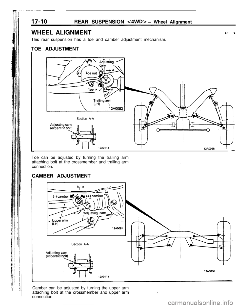
WHEEL ALIGNMENT
This rear suspension has a toe and camber adjustment mechanism.
TOE ADJUSTMENT
Section A-A
Iv’ ‘PI I
12AOllOI12AOO58I-Toe can be adjusted by turning the trailing arm
attaching bolt at the crossmember and trailing arm
connection.
,CAMBER ADJUSTMENT
I
(-1 cam&r @L Y i+) camber 7\\
__cc \
----7--w
’ --
12AcoEl
e /Adjusting cam&\\Adjusting
(eccentric
Section A-ACamber can be adjusted by turning the upper arm
attaching bolt at the crossmember and upper arm
connection..
Page 204 of 391
. -.-REAR SUSPENSION
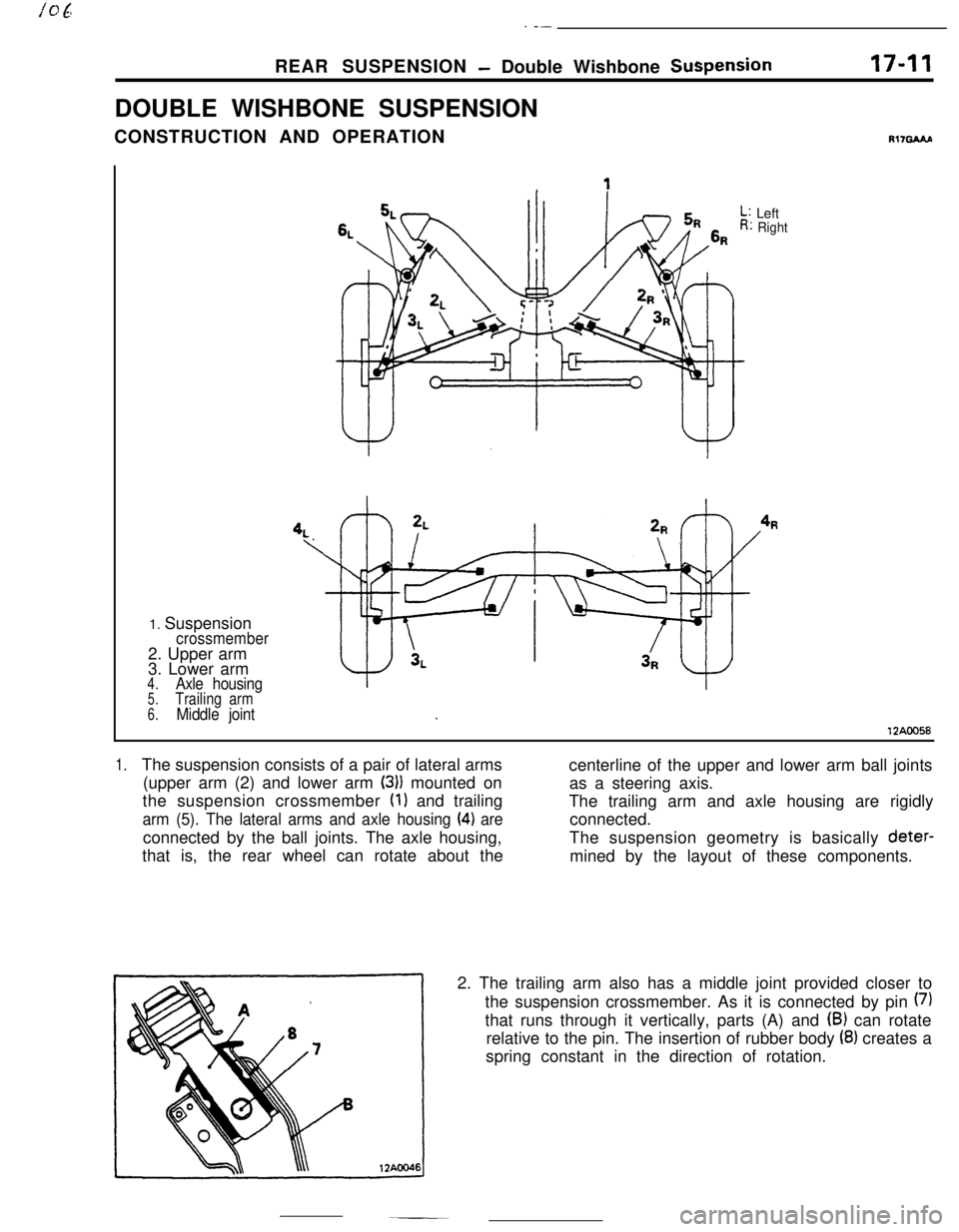
- Double Wishbone SuspensionDOUBLE WISHBONE SUSPENSION
CONSTRUCTION AND OPERATION17-11
R17GAAP1. Suspension
crossmember2. Upper arm
3. Lower arm
4.Axle housing5.Trailing arm
6.Middle jointLeft
Right
12AOO58
1.The suspension consists of a pair of lateral arms
centerline of the upper and lower arm ball joints
(upper arm (2) and lower arm
(3)) mounted on
as a steering axis.
the suspension crossmember
(1) and trailing
The trailing arm and axle housing are rigidly
arm (5). The lateral arms and axle housing (4) areconnected.
connected by the ball joints. The axle housing,The suspension geometry is basically deter-
that is, the rear wheel can rotate about the
mined by the layout of these components.
2. The trailing arm also has a middle joint provided closer to
the suspension crossmember. As it is connected by pin
(7)that runs through it vertically, parts (A) and
(B) can rotate
relative to the pin. The insertion of rubber body
(8) creates a
spring constant in the direction of rotation.