diagram MITSUBISHI ECLIPSE 1990 Owner's Manual
[x] Cancel search | Manufacturer: MITSUBISHI, Model Year: 1990, Model line: ECLIPSE, Model: MITSUBISHI ECLIPSE 1990Pages: 391, PDF Size: 15.27 MB
Page 206 of 391
-
REAR SUSPENSION -Double Wishbone Suspension17-13
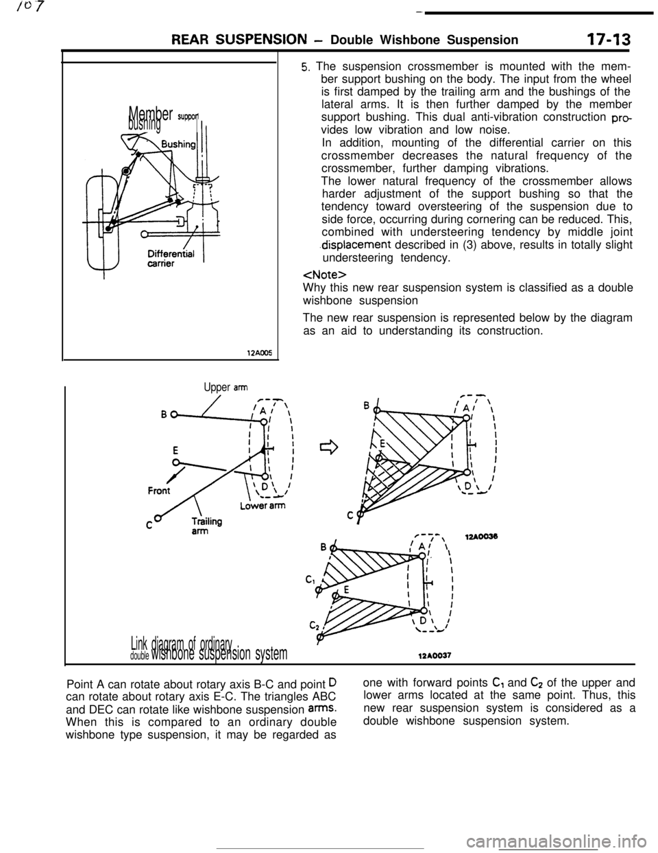
Member supponbushingI
12AOO5
Upper arm
Link diagram of ordinarydouble wishbone suspension system
5. The suspension crossmember is mounted with the mem-
ber support bushing on the body. The input from the wheel
is first damped by the trailing arm and the bushings of the
lateral arms. It is then further damped by the member
support bushing. This dual anti-vibration construction
provides low vibration and low noise.
In addition, mounting of the differential carrier on this
crossmember decreases the natural frequency of the
crossmember, further damping vibrations.
The lower natural frequency of the crossmember allows
harder adjustment of the support bushing so that the
tendency toward oversteering of the suspension due to
side force, occurring during cornering can be reduced. This,
combined with understeering tendency by middle joint
.displacement described in (3) above, results in totally slight
understeering tendency.
wishbone suspension
The new rear suspension is represented below by the diagram
as an aid to understanding its construction.
F-7-,12AOO33!A/ \
12AOO37Point A can rotate about rotary axis B-C and point
Dcan rotate about rotary axis E-C. The triangles ABC
and DEC can rotate like wishbone suspension
arms.When this is compared to an ordinary double
wishbone type suspension, it may be regarded asone with forward points
C, and C2 of the upper and
lower arms located at the same point. Thus, this
new rear suspension system is considered as a
double wishbone suspension system.
Page 266 of 391
21-42AUTOMATIC TRANSAXLE - Transaxle Control
ELECTRONIC CONTROL DEVICE
DAMPER CLUTCH CONTROL
The damper clutch is engaged or disengaged
according to the “map” stored in the transaxle
control unit.
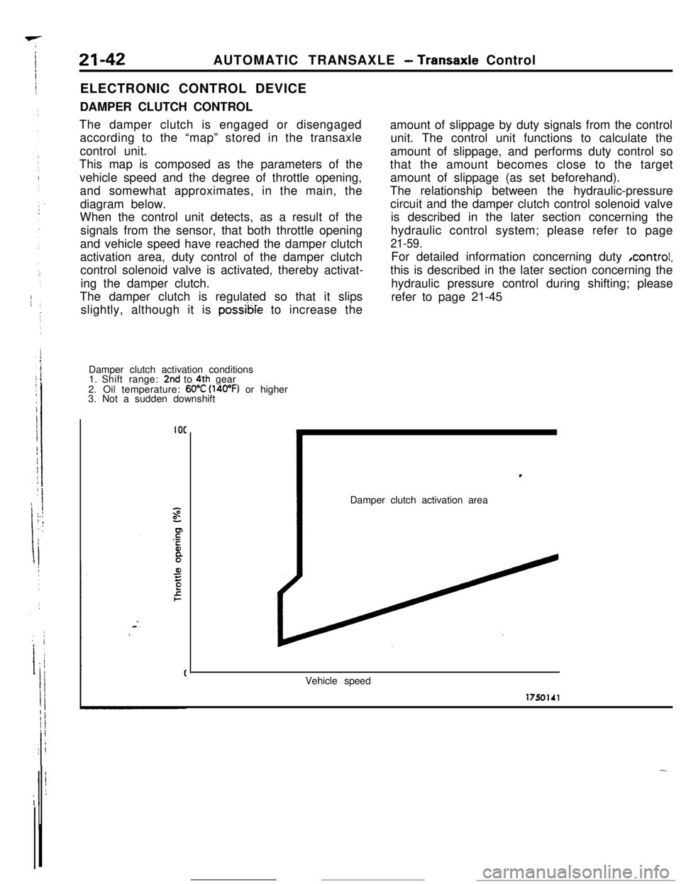
This map is composed as the parameters of the
vehicle speed and the degree of throttle opening,
and somewhat approximates, in the main, the
diagram below.
When the control unit detects, as a result of the
signals from the sensor, that both throttle opening
and vehicle speed have reached the damper clutch
activation area, duty control of the damper clutch
control solenoid valve is activated, thereby activat-
ing the damper clutch.
The damper clutch is regulated so that it slips
slightly, although it is
possible to increase the
Damper clutch activation conditions
1. Shift range:
2nd to 4th gear
2. Oil temperature: 60°C (l4oOF) or higher
3. Not a sudden downshift
IOCamount of slippage by duty signals from the control
unit. The control unit functions to calculate the
amount of slippage, and performs duty control so
that the amount becomes close to the target
amount of slippage (as set beforehand).
The relationship between the hydraulic-pressure
circuit and the damper clutch control solenoid valve
is described in the later section concerning the
hydraulic control system; please refer to page
21-59.For detailed information concerning duty ,control,
this is described in the later section concerning the
hydraulic pressure control during shifting; please
refer to page 21-45,
Damper clutch activation area
Vehicle speed
Page 318 of 391
--
,
; ’I :j:.
i
-21-96AUTOMATIC TRANSAXLE
- Transaxle Control
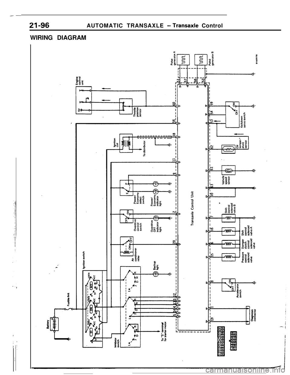
WIRING DIAGRAMDD<
D
C
C
22C
2
5v0,‘ii2t6c
C
C
C
C
C
C
Page 339 of 391
23-22BODY - Power Windows
POWER WINDOWS
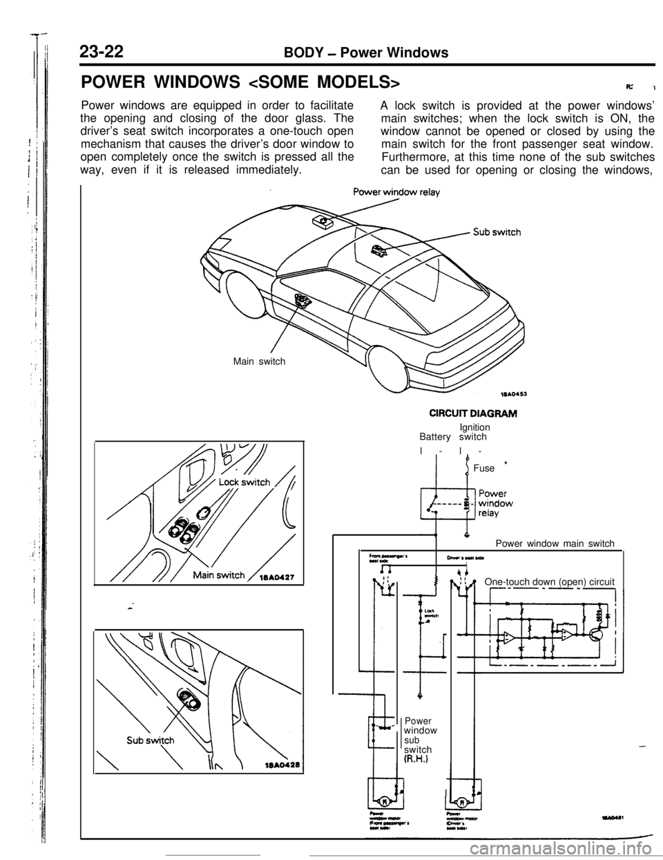
R’1Power windows are equipped in order to facilitate
A lock switch is provided at the power windows’
the opening and closing of the door glass. The
main switches; when the lock switch is ON, the
driver’s seat switch incorporates a one-touch open
mechanism that causes the driver’s door window towindow cannot be opened or closed by using the
main switch for the front passenger seat window.
open completely once the switch is pressed all the
way, even if it is released immediately.Furthermore, at this time none of the sub switches
can be used for opening or closing the windows,
Main switch
CIRCUIT DIAGRAMIgnition
Battery switch
l-l-
’ 1Fuse ’
Z*,“““”CrPower window main switch
-*W(WlI. _;:
r-
L
--e.
.
I
ELnA
I
Powerwindow
subswitch
(R.H.)
I IOne-touch down (open) circuit
--P’-‘-,
-
Page 353 of 391
23-36BODY -Seat Belts
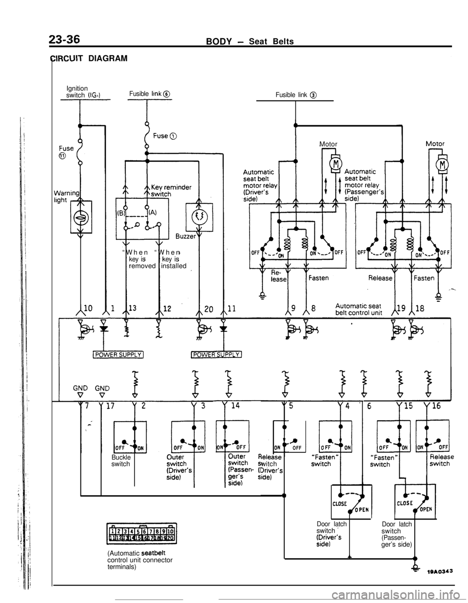
IRCUIT DIAGRAM
Ignition
switch
(IGIlFusible llnk @
-T- --T-
A10“When “When
key iskey isremoved installed
Fusible link @
Buckleswitch
(Automatic seatbelt
control unit connector
terminals)leiease
witch
?r$r’s
0Motor
c,OFF
6
Door latchswitch ’fDr:r’s
Door latchswitch
(Passen-ger’s side)
A?
-f&19*0343
Page 367 of 391
L.
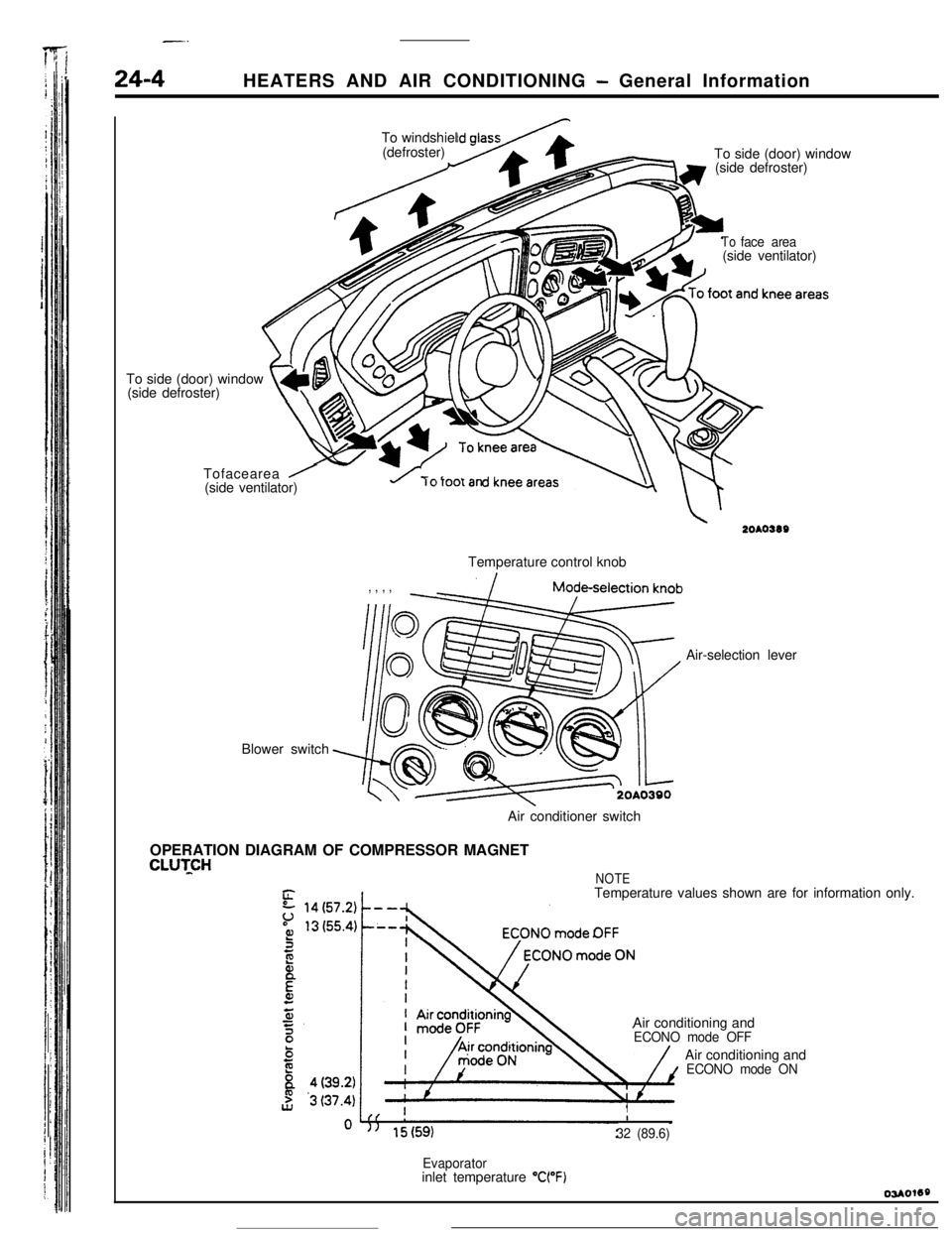
24-4HEATERS AND AIR CONDITIONING - General Information
’ /To side (door) window
(side defroster)
t4L\ m\vTofacearea
/(side ventilator)To windshiel
(defroster)
To side (door) window
(side defroster)
Blower switch
Toface area(side ventilator)
u rorootanTemperature control knob
, , , ,Air-selection lever
Air conditioner switch
OPERATION DIAGRAM OF COMPRESSOR MAGNET
CLUTCHNOTETemperature values shown are for information only.
Air conditioning and
ECONO mode OFFAir conditioning and
ECONO mode ON
II
32 (89.6)
Evaporatorinlet temperature “WF)