rod MITSUBISHI ECLIPSE 1990 Owner's Manual
[x] Cancel search | Manufacturer: MITSUBISHI, Model Year: 1990, Model line: ECLIPSE, Model: MITSUBISHI ECLIPSE 1990Pages: 391, PDF Size: 15.27 MB
Page 335 of 391
23-18BODY -Body Color Code / Body Color Code Interpretation / Solid
izsiii
Noofl -ENGINE -TNANS I
coLm %F
-T-iI/IBody color code0010163BODY COLOR CODE
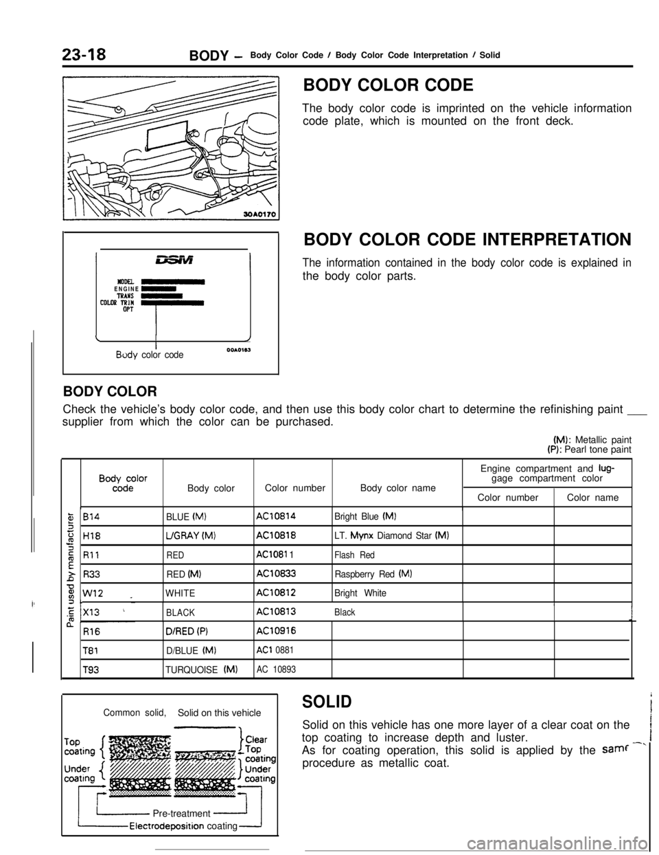
The body color code is imprinted on the vehicle information
code plate, which is mounted on the front deck.
BODY COLOR CODE INTERPRETATION
The information contained in the body color code is explained inthe body color parts.
BODY COLOR
Check the vehicle’s body color code, and then use this body color chart to determine the refinishing paint ___
supplier from which the color can be purchased.(M): Metallic paint
(P): Pearl tone paint
B”%d:‘orBody colorColor numberBody color nameEngine compartment and
lug-gage compartment color
Color numberColor name
,814
H18
Rll
R33
w12 _c
BLUE (MI
UGRAY (Mvt)
RED
RED (MI
WHITE
AC10814
AC10818
AC1081 1
AC10833
AC10812Bright Blue
(MI
LT. Mynx
Diamond Star (MI
Flash Red
Raspberry Red (MI
Bright White
BLACKAC10813Black
n R16
T81
T93
D/RED (PIAC10916
D/BLUE (Ml
AC1 0881
TURQUOISE (MIAC 10893
SOLID
i
Common solid,Solid on this vehicleISolid on this vehicle has one more layer of a clear coat on the
Itop coating to increase depth and luster.
IAs for coating operation, this solid is applied by the samf
-”procedure as metallic coat.
I Pre-treatmentElectrodeposition coating
Page 344 of 391
BODY- Door Mirrors .23-27
DOOR MIRRORSIPIKhAC
.i~e large-size Talbot mirrors are attached on the
front doors that smoothly blend into the body
styling. They also contribute to the reduced aerody-
namic drag.
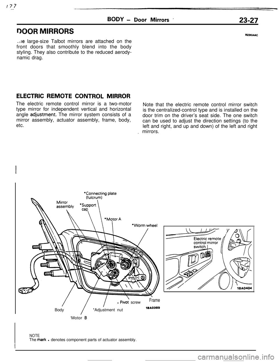
ELECTRIC REMOTE CONTROL MIRRORThe electric remote control mirror is a two-motor
type mirror for independent vertical and horizontalNote that the electric remote control mirror switch
angle
adjustment The mirror system consists of ais the centralized-control type and is installed on the
mirror assembly, actuator assembly, frame, body,door trim on the driver’s seat side. The one switch
etc.can be used to adjust the direction settings (to the
left and right, and up and down) of the left and right
_ mirrors.
/
/
l Pivo; screwFrameBody*Adjustment nutleAo398
‘Motor
B
NOTE
IThe &ark l denotes component parts of actuator assembly.
I
Page 349 of 391
23-32BODY - Seat Belts
OPERATION OF AUTOMATIC SEAT BELTS
The operation of the Automatic Seat Belts is as follows.
(1) The belts fasten itself around the occupant when the front
door is closed with the ignition switch in the “ON” position.
(2) The belts release itself from the occupant when the front
door is opened with the ignition switch in the
*“ON” or
“LOCK” or “ACC” position.
(3) The belts cease to fasten itself around the occupant if the
ignition switch is turned to “LOCK” or “ACC” or when the
front door is opened during the belt motion.
(4) The belts for the driver’s and front passenger’s seats
operate independently of each other.
Lever springStopper, Rod A
Sub paw1
Gear B
Rod B19po37:
Sub’pawlIWO374
IStopperGear AI
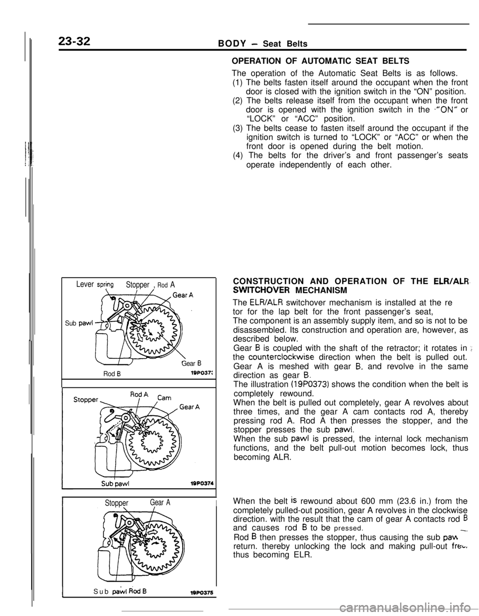
ISub pai.4 dodB1980376CONSTRUCTION AND OPERATION OF THE
ELR/ALR,
SWITCHOVER MECHANISM
The
ELR/ALR switchover mechanism is installed at the re
tor for the lap belt for the front passenger’s seat,
The component is an assembly supply item, and so is not to be
disassembled. Its construction and operation are, however, as
described below.
Gear
B is coupled with the shaft of the retractor; it rotates in ::the counterclockwise direction when the belt is pulled out.
Gear A is meshed with gear
B, and revolve in the same
direction as gear
B.The illustration
(19PO373) shows the condition when the belt is
completely rewound.
When the belt is pulled out completely, gear A revolves about
three times, and the gear A cam contacts rod A, thereby
pressing rod A. Rod A then presses the stopper, and the
stopper presses the sub
pawl.When the sub pawl is pressed, the internal lock mechanism
functions, and the belt pull-out motion becomes lock, thus
becoming ALR.
When the belt
is rewound about 600 mm (23.6 in.) from the
completely pulled-out position, gear A revolves in the clockwise
direction. with the result that the cam of gear A contacts rod
6and causes rod
B to be pressed.
Rod
B then presses the stopper, thus causing the sub pan -return. thereby unlocking the lock and making pull-out
freti.thus becoming ELR.
Page 370 of 391

HEATERS AND AIR CONDITIONING - Heater Construction24-7
IKnob posltionDamper position and air flow direction
Air outflow locations
Outside air
Recircu-lation air
2010246
Recircu-iation airDEF
2OAO247Temperature Control Knob
IKnob positionDamper position and air ‘flow directionOperation
When the temperature control knob or
the heater control is rotated fully
counterclockwise toward the cool air
position, the upper side of the heater
core will be blocked up by the blend
air damper A. whereas the lower side
of the heater core
will be blocked up by
the blend air damper 8. As a result.
all the air from the blower motor does
not pass through the heater core but
directly flows out as cool air.
Blend air damper CBlend air damper A
x!= cY?l-nY-/
-1 From
To air Voutflowopenings*blower
motor
Hester ‘OreOUO,,O
Blend air damper CBlend air damper A,//7When the temperature control knob of
the heater control is rotated fully
ctockwise toward the warm air position.the blend air dampers A and Bwill block the cool air paths.
The cool air from the blower motor
passes through the heater core for
maximum heating..
Tooutflow
openings
Blend al’r damper B
When the temperature control knob of
the heater control is rotated to the
mid position, the blend air dampers A
and B will split the air stream intotwo branches, one passing through the
heater core and one not passing through
the heater core. The blend damper air
Cintroduces cool air from the heater core
top into the heater unit chamber. Air
conditioning is provided by mixing this
cool air with hot air heated by the
heater cores.
Blend air damper CBlend/ air damper AL
2OAO391Blend air damoer B
--.-__.__ ,_ .
Page 374 of 391
25-2EMISSION CONTROL SYSTEMS - General Information
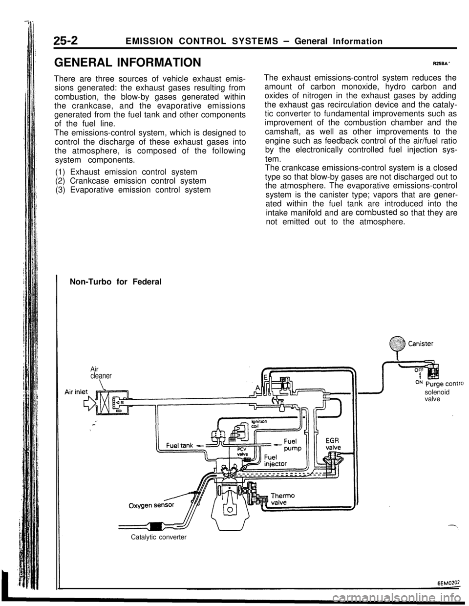
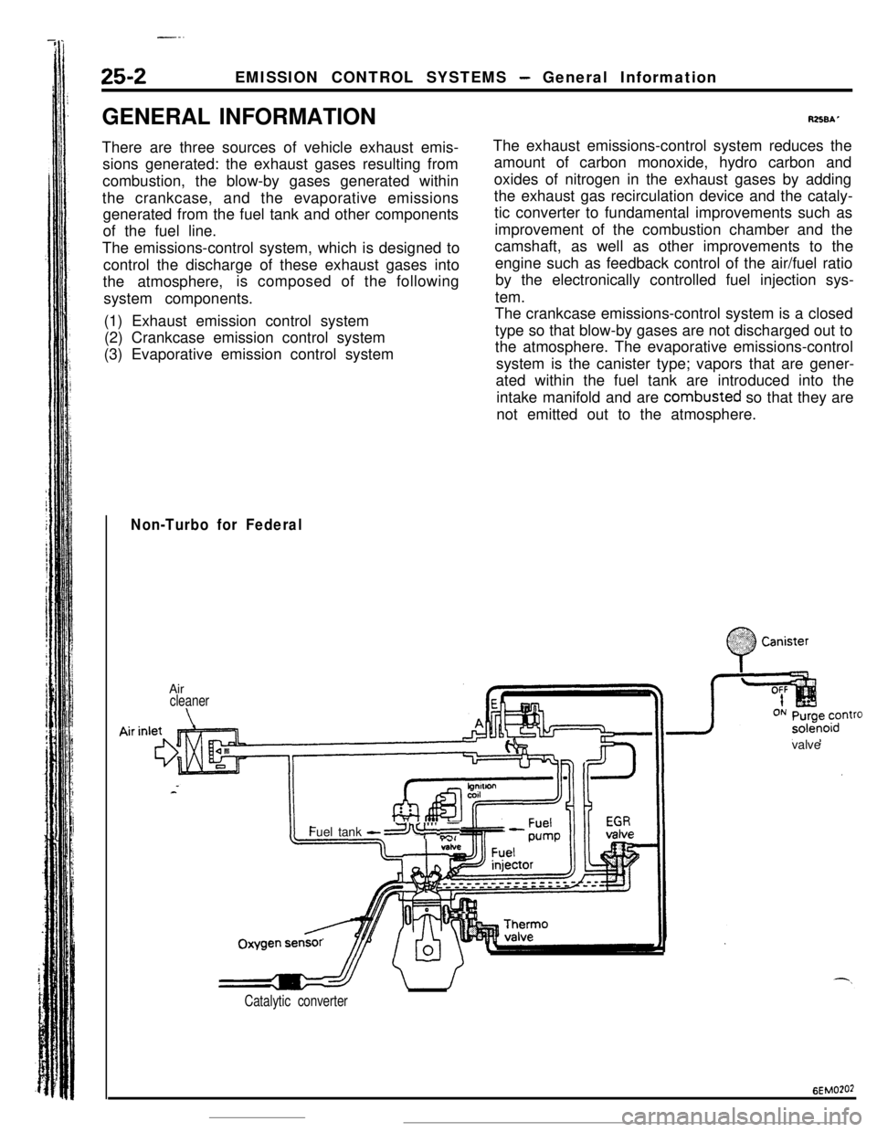
GENERAL INFORMATION
There are three sources of vehicle exhaust emis-
sions generated: the exhaust gases resulting from
combustion, the blow-by gases generated within
the crankcase, and the evaporative emissions
generated from the fuel tank and other components
of the fuel line.
The emissions-control system, which is designed to
control the discharge of these exhaust gases into
the atmosphere, is composed of the following
system components.
(1) Exhaust emission control system
(2) Crankcase emission control system
(3) Evaporative emission control system
R258A’The exhaust emissions-control system reduces the
amount of carbon monoxide, hydro carbon and
oxides of nitrogen in the exhaust gases by adding
the exhaust gas recirculation device and the cataly-
tic converter to fundamental improvements such as
improvement of the combustion chamber and the
camshaft, as well as other improvements to the
engine such as feedback control of the air/fuel ratio
by the electronically controlled fuel injection sys-
tem.
The crankcase emissions-control system is a closed
type so that blow-by gases are not discharged out to
the atmosphere. The evaporative emissions-control
system is the canister type; vapors that are gener-
ated within the fuel tank are introduced into the
intake manifold and are combusted so that they are
not emitted out to the atmosphere.
Non-Turbo for Federal
Air
cleaner
\solenoid
valve
Catalytic converter
:
0
$2:) Canister:.:
Page 376 of 391
--.
25-2EMISSION CONTROL SYSTEMS - General Information
GENERAL INFORMATION
There are three sources of vehicle exhaust emis-
sions generated: the exhaust gases resulting from
combustion, the blow-by gases generated within
the crankcase, and the evaporative emissions
generated from the fuel tank and other components
of the fuel line.
The emissions-control system, which is designed to
control the discharge of these exhaust gases into
the atmosphere,is composed of the following
system components.
(1) Exhaust emission control system
(2) Crankcase emission control system
(3) Evaporative emission control system
RZSBAThe exhaust emissions-control system reduces the
amount of carbon monoxide, hydro carbon and
oxides of nitrogen in the exhaust gases by adding
the exhaust gas recirculation device and the cataly-
tic converter to fundamental improvements such as
improvement of the combustion chamber and the
camshaft, as well as other improvements to the
engine such as feedback control of the air/fuel ratio
by the electronically controlled fuel injection sys-
tem.
The crankcase emissions-control system is a closed
type so that blow-by gases are not discharged out to
the atmosphere. The evaporative emissions-control
system is the canister type; vapors that are gener-
ated within the fuel tank are introduced into the
intake manifold and are combusted so that they are
not emitted out to the atmosphere.
Non-Turbo for Federal
.;. :
0
.%??? CanisterAir
cleaner
\valveOxygenFuel tank
-a I”’ ,T
sensr’
Catalytic converter
6EMO?O2
Page 383 of 391
---- .~ _ _EMISSION CONTROL SYSTEMS
- Catalytic Converter I Air-fuel Mixture Ratio Control System25-9
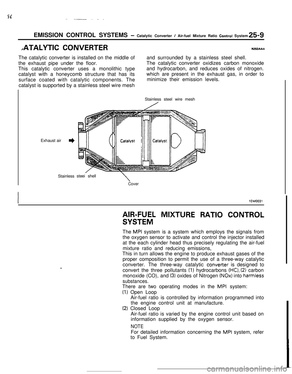
,ATALYTlC CONVERTERRZXIAAAThe catalytic converter is installed on the middle ofand surrounded by a stainless steel shell.
the exhaust pipe under the floor.The catalytic converter oxidizes carbon monoxide
This catalytic converter uses a monolithic type
catalyst with a honeycomb structure that has itsand hydrocarbon, and reduces oxides of nitrogen.
surface coated with catalytic components. Thewhich are present in the exhaust gas, in order to
minimize their emission levels.
catalyst is supported by a stainless steel wire mesh
Exhaust air
3Stainlesssteei shell
\CoverStainless steel wire mesh
lEM0031
AIR-FUEL MIXTURE RATIO CONTROL
SYSTEMThe
MPI system is a system which employs the signals from
the oxygen sensor to activate and control the injector installed
at the each cylinder head thus precisely regulating the air-fuel
mixture ratio and reducing emissions,
This in turn allows the engine to produce exhaust gases of the
proper composition to permit the use of a three-way catalytic
converter. The three-way catalytic converter is designed to
convert the three pollutants
(1) hydrocarbons (HC), (2) carbon
monoxide (CO), and
(3) oxides of Nitrogen (NOx) into harmiess
substances.There are two operating modes in the
MPI system:
(1) Open Loop
Air-fuel ratio is controlled by information programmed into
the engine control unit at manufacture.
(2) Closed Loop
Air-fuel ratio is varied by the engine control unit based on
information supplied by the oxygen sensor.
NOTEFor detailed information concerning the
MPI system, refer
to Fuel System.
Page 387 of 391

EMISSION CONTROL SYSTEMS- Evaporative Emission Control System25-13
IFrom canister1
,To intake air plenum or throttle body
7EMOlPControl
relavPurge control
solenoid valve
Battery
g
6
,zEngine control
unit
From throttle body
4To purge
control
valve
SEMo2laControl relay
3:
1.
Purge control
solenoid valve
zBattery g
Engtne controlunii
bfuo532JPURGE CONTROL SOLENOID VALVE
The purge-control solenoid valve is the ON/OFF control type of
solenoid valve; it functions to control the introduction of purge
air to the intake air plenum from the canister.
PURGE CONTROL SOLENOID VALVE
The purge-control solenoid valve is the ON/OFF control type of
solenoid valve; it functions to control the activation of the
purge-control valve.
ITo throttle body11PURGE CONTROL VALVE
The purge-control valve functions to control the introduction of
purge air to the air-intake hose from the canister.
0 From canister
Page 388 of 391
--.25-14EMISSION CONTROL SYSTEMS
- Evaporative Emisson Control System
Pressure valveTo overfill
’ limiter
40
” Ball
Bail
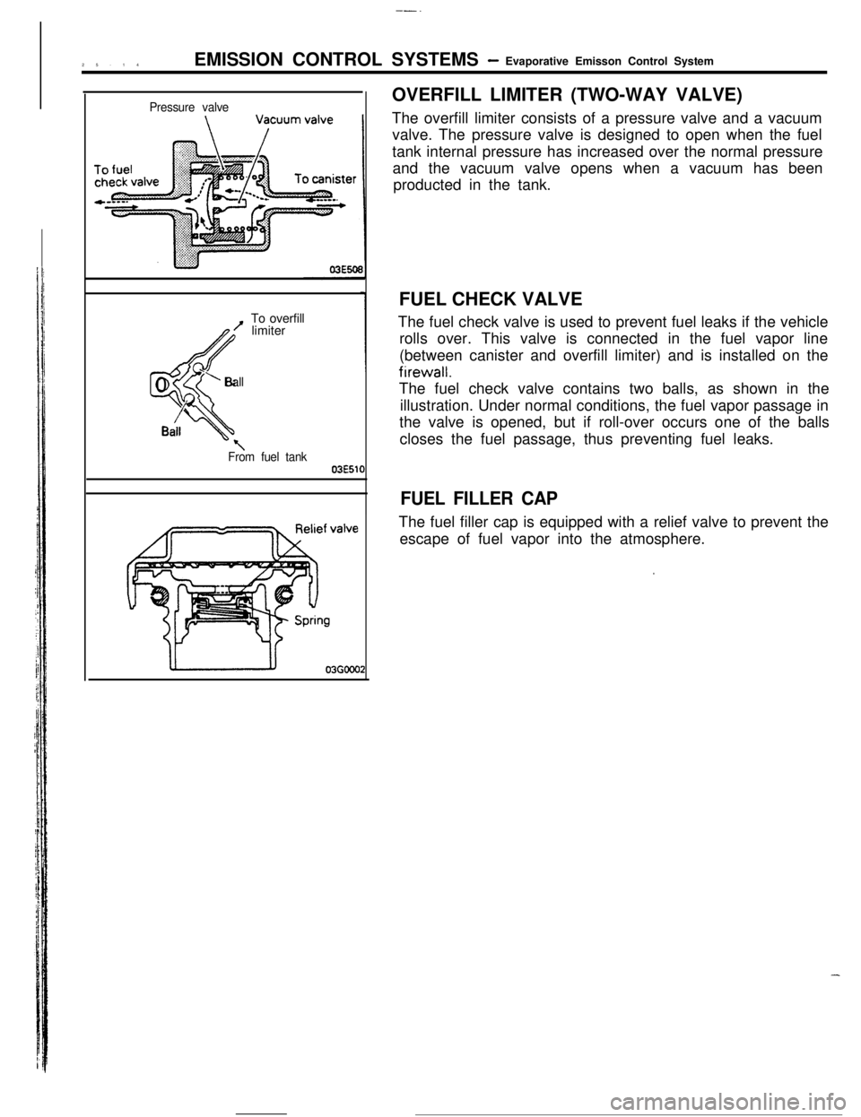
\From fuel tank03E51fOVERFILL LIMITER (TWO-WAY VALVE)
The overfill limiter consists of a pressure valve and a vacuum
valve. The pressure valve is designed to open when the fuel
tank internal pressure has increased over the normal pressure
and the vacuum valve opens when a vacuum has been
producted in the tank.
FUEL CHECK VALVE
The fuel check valve is used to prevent fuel leaks if the vehicle
rolls over. This valve is connected in the fuel vapor line
(between canister and overfill limiter) and is installed on thefirewall.
The fuel check valve contains two balls, as shown in the
illustration. Under normal conditions, the fuel vapor passage in
the valve is opened, but if roll-over occurs one of the balls
closes the fuel passage, thus preventing fuel leaks.
FUEL FILLER CAPThe fuel filler cap is equipped with a relief valve to prevent the
escape of fuel vapor into the atmosphere.
.
-
Page 391 of 391
UNITED STATES
The special service tools referred to herein are required for certain service operations. These special service tools
or their equivalent, if not obtainable through a local source are available through the following outlet.32615 Park Lane, Garden City, Michigan 48135, U.S.A.
TRIANGLE SPECIAL PRODUCTS GROUP
(MILLER SPECIAL TOOLS)
DIVISION OF THE TRIANGLE CORPORATION
CANADA .
b’f CANADA
1, CHRYSLERThe special service tools referred to herein are required for certain service operations. These special
service tools
or their equivalent, if not obtainable through a local source are available through the following outlet.
C 8r D Riley Enterprises Ltd., P.O. Box 243, Amherstburg, Ontario N9V 224INTERNATIONAL
!!!hif INTERNA’IIONAL
1, CHRYSLERThe special service toOk referred to herein are required for certain service operations. These special
service tools
or their equivalent, if not obtainable through a local source are available through the following outlet.
32615 Park Lane, Garden City, Michigan 48135, U.S.A.
TRIANGLE SPECIAL PRODUCTS GROUP
(MILLER SPECIAL TOOLS)
DIVISION OF THE TRIANGLE CORPORATION