ESP MITSUBISHI ECLIPSE 1990 Service Manual
[x] Cancel search | Manufacturer: MITSUBISHI, Model Year: 1990, Model line: ECLIPSE, Model: MITSUBISHI ECLIPSE 1990Pages: 391, PDF Size: 15.27 MB
Page 8 of 391
o-4GENERAL - Technical Features
BASIC CONSTRUCTION
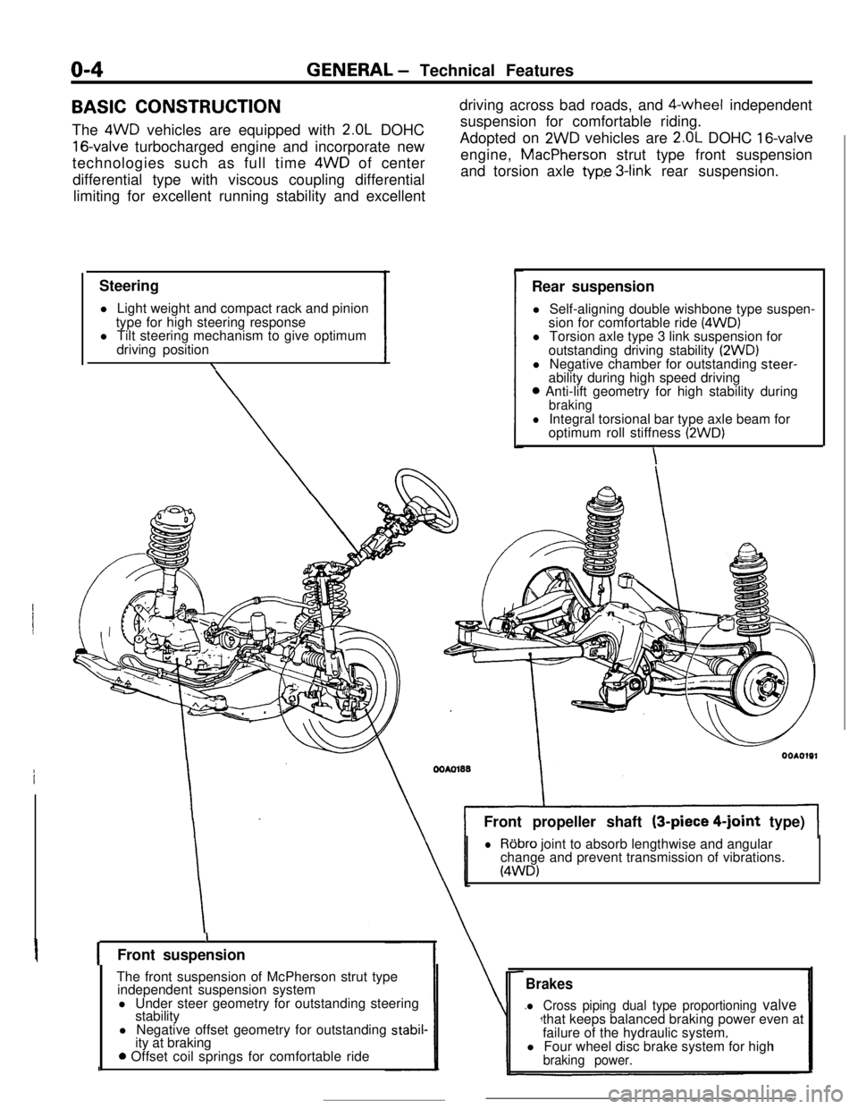
The 4WD vehicles are equipped with
2.OL DOHC
16-valve turbocharged engine and incorporate new
technologies such as full time 4WD of center
differential type with viscous coupling differential
limiting for excellent running stability and excellent
Steering
l Light weight and compact rack and pinion
type for high steering response
l Tilt steering mechanism to give optimum
driving position
\driving across bad roads, and $-wheel independent
suspension for comfortable riding.
Adopted on
2WD vehicles are 2.OL DOHC 16-valveengine, MacPherson strut type front suspension
and torsion axle
typ.e 3-link rear suspension.
Rear suspension
l Self-aligning double wishbone type suspen-
sion for comfortable ride
(4WD)l Torsion axle type 3 link suspension for
outstanding driving stability
(2WD)l Negative chamber for outstanding steer-
ability during high speed driving
0 Anti-lift geometry for high stability duringbraking
lIntegral torsional bar type axle beam for
optimum roll stiffness (2WD)
\Front propeller shaft (3-piece
4-joint type)
lRobro joint to absorb lengthwise and angular
change and prevent transmission of vibrations.
(4WD)
IFront suspension
The front suspension of McPherson strut type
independent suspension system
l Under steer geometry for outstanding steering
stability
l Negative offset geometry for outstanding
stabil-ity at braking
0 Offset coil springs for comfortable ride
Brakes
l Cross piping dual type proportioning valvethat keeps balanced braking power even at
failure of the hydraulic system.
l Four wheel disc brake system for high
braking power.
Page 9 of 391
GENERAL - Technical Featureso-5ENGINE
The engines are the transverse-mounted engine
especially for front-engine/front-wheeldrive orfront-engine/4-wheel drive models, the
2.OL DOHC
16-valve engine with high-performance, silent-
operation,low-vibration,low-noise,low-fuel-
consumption features, an engine that fully displays
the most
up-todate engine technology.
SPECIFICATIONS
Engine model
Displacement
cc (cu.in.1
h$xo$put (SAE net)Max. torque (SAE net)
ft.Ibs./rpm
4G63Non-Turbo1997(122)135/6000125/5000
4663Turbo1997(122)195/6000203/3000
FEATURESHigh performance and low fuel consumption
l The rocker arm reduces the valve-actuation torque as well as fuel consumption.
l Air-intake efficiency improved through the adoption of the optimum air-intake system layout.
l Improved response and fuel consumption has been achieved by electronic control multipoint
fuel injection.
l Water-cooled turbocharger.
Quiet operation
l Noise and vibration have been decreased by the adoption of roller rocker arms.
l Noise generated by the valve mechanism has been decreased by the hydraulic auto lash adjusters.
l Vibrations have been decreased by the adoption of bearing caps with beams which increase the
rigidity of the crankshaft support points.
-Serviceability
l Complete self-diagnosis functions.
l Enhanced reliability through the adoption of gold-plated connector terminals.
l Use of an auto tensioner achieves maintenance-free, automatic adjustment of timing belt
tension.
l Use of the auto lash adjusters achieves maintenance-free, automatic adjustment of valve clearance
.o The 2coil ignition system without a distributor supplies sufficient ignition energy even during
high speed operation.
Page 23 of 391
FRONT SUSPENSION - Anti-dive Geometry / Negative-offset Geometry2-5ANTI-DIVE GEOMETRY
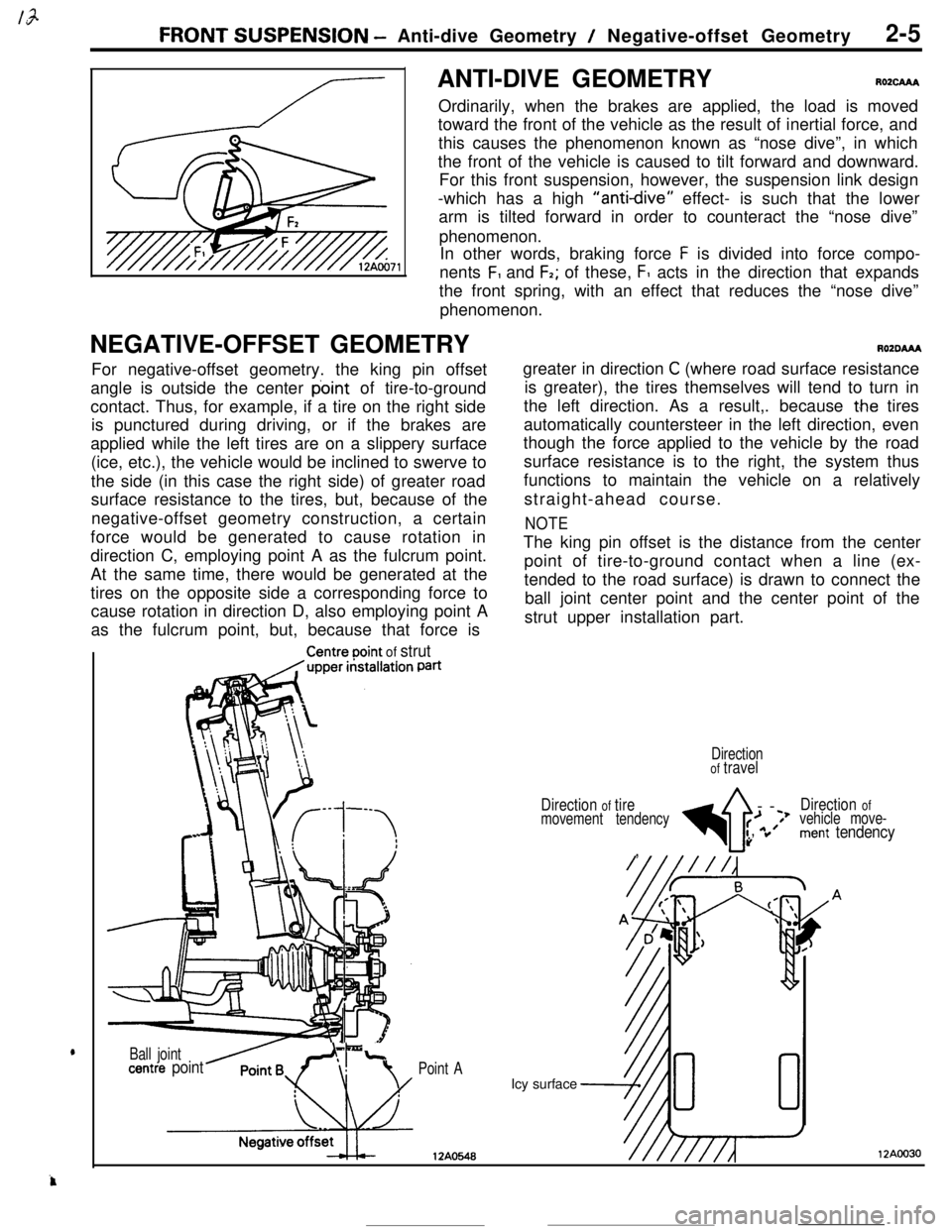
RO2cAAAOrdinarily, when the brakes are applied, the load is moved
toward the front of the vehicle as the result of inertial force, and
this causes the phenomenon known as “nose dive”, in which
the front of the vehicle is caused to tilt forward and downward.
For this front suspension, however, the suspension link design
-which has a high
“anti-dive” effect- is such that the lower
arm is tilted forward in order to counteract the “nose dive”
phenomenon.
In other words, braking force
F is divided into force compo-
nents
F, and F2; of these, F1 acts in the direction that expands
the front spring, with an effect that reduces the “nose dive”
phenomenon.
NEGATIVE-OFFSET GEOMETRY
AOZDAAAFor negative-offset geometry. the king pin offset
angle is outside the center point of tire-to-ground
contact. Thus, for example, if a tire on the right side
is punctured during driving, or if the brakes are
applied while the left tires are on a slippery surface
(ice, etc.), the vehicle would be inclined to swerve to
the side (in this case the right side) of greater road
surface resistance to the tires, but, because of the
negative-offset geometry construction, a certain
force would be generated to cause rotation in
direction C, employing point A as the fulcrum point.
At the same time, there would be generated at the
tires on the opposite side a corresponding force to
cause rotation in direction D, also employing point A
as the fulcrum point, but, because that force is
Centreooint of strutPatigreater in direction
C (where road surface resistance
is greater), the tires themselves will tend to turn in
the left direction. As a result,. because
t.he tires
automatically countersteer in the left direction, even
though the force applied to the vehicle by the road
surface resistance is to the right, the system thus
functions to maintain the vehicle on a relatively
straight-ahead course.
NOTEThe king pin offset is the distance from the center
point of tire-to-ground contact when a line (ex-
tended to the road surface) is drawn to connect the
ball joint center point and the center point of the
strut upper installation part.
Point AIcy surface
12AO548
Ball jointLcentre point
Directionof travel
Direction
of tire
4--
Direction ofmovement tendency>f;’*Jvehicle move-:’
”ment tendency,
12AOO30
Page 32 of 391
REAR AXLE- Viscous Coupling Type Limited Slip Differential3-a
DIFFERENTIALROlEAM
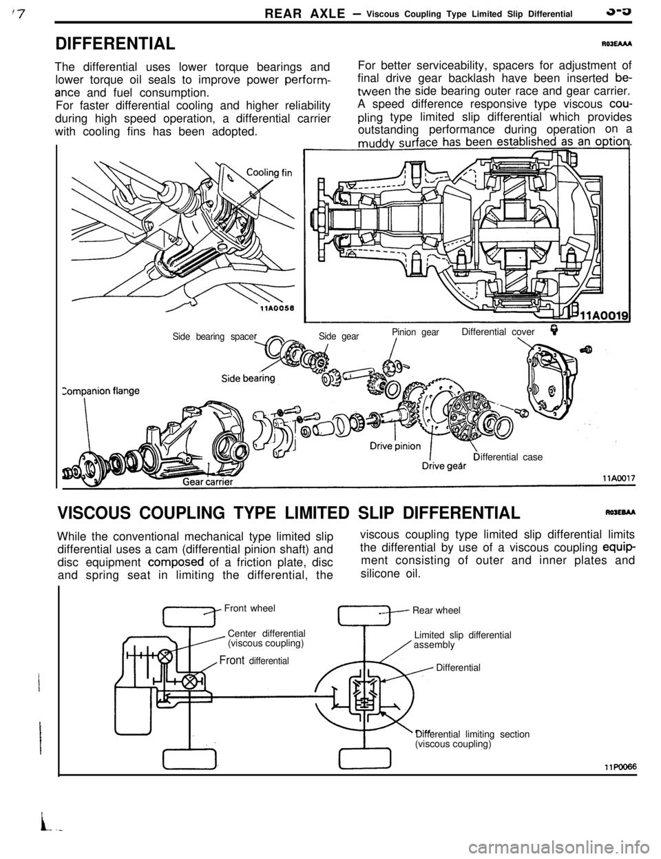
The differential uses lower torque bearings and
lower torque oil seals to improve power perform-
ante and fuel consumption.
For faster differential cooling and higher reliability
during high speed operation, a differential carrier
with cooling fins has been adopted.For better serviceability, spacers for adjustment of
final drive gear backlash have been inserted
be-tween the side bearing outer race and gear carrier.
A speed difference responsive type viscous
cou-
pling type limited slip differential which provides
outstandingperformance during operationon a
Side gearPinion gearDifferential coverQ./\Side bearing spaceifferential case
VISCOUS COUPLING TYPE LIMITED SLIP DIFFERENTIALRWEBAAWhile the conventional mechanical type limited slip
differential uses a cam (differential pinion shaft) and
disc equipment
compo.sed of a friction plate, disc
and spring seat in limiting the differential, theviscous coupling type limited slip differential limits
the differential by use of a viscous coupling equip-
ment consisting of outer and inner plates and
silicone oil.
Front wheel
Center differential
’ (viscous coupling)Rear wheel
Limited slip differential
assembly
Front differential, I
TDifferential
Differential limiting section
(viscous coupling)11KmI66
L.-
Page 33 of 391
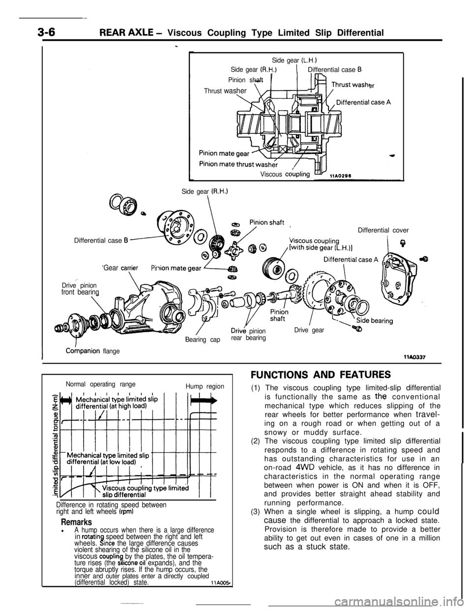
3-6REAR AXLE - Viscous Coupling Type Limited Slip Differential
Is
Side gear (L.H.)
Side gear (R.H.)1Differential case B
Pinion shaft
Thrust
washer
Viscous cokpling
3r
Side gear U3.H.)Differential case
B
, ,,Differential cover
I
‘Gear cagierPir
,Drive pinionfront bearing
Driv& pinionDrive gear
Bearing caprear bearing
ICokpanion flangellAo337
Normal operating range
Hump region
Difference in rotating speed between
right and left wheels (rpm)
RemarkslA hump occurs when there is a large differencein rotatinwheels..!speed between the right and leftlnce the large difference causes
violent shearing of the silicone oil in the
viscous couplin7.by the plates, the oil tempera-
ture rises (the SI Icone 011 expands), and the
torque abruptly rises. If the hump occurs, the
inner and outer plates enter a directly coupled(differential locked) state.llAOO5r
FUNCTIONS AND FEATURES(1) The viscous coupling type limited-slip differential
is functionally the same as
the conventional
mechanical type which reduces slipping of the
rear wheels for better performance when travel-
ing on a rough road or when getting out of a
snowy or muddy surface.
(2) The viscous coupling type limited slip differential
responds to a difference in rotating speed and
has outstanding characteristics for use in an
on-road
4WD vehicle, as it has no difference in
characteristics in the normal operating range
between when power is ON and when it is OFF,
and provides better straight ahead stability and
running performance.
(3) When a single wheel is slipping, a hump could
cause the differential to approach a locked state.
Provision is therefore made to provide a better
ability to get out even in cases of one in a million
such as a stuck state.
Page 77 of 391
IGNITION SYSTEMELECTRICAL - Engine Electrical8-25
I
Sensors
Engine control unitlgnltlon switch
Battery
11 IPower transfstor
hhP 1
Ilgnltion coil
C To tachometerTerminal for engine
speed detectton
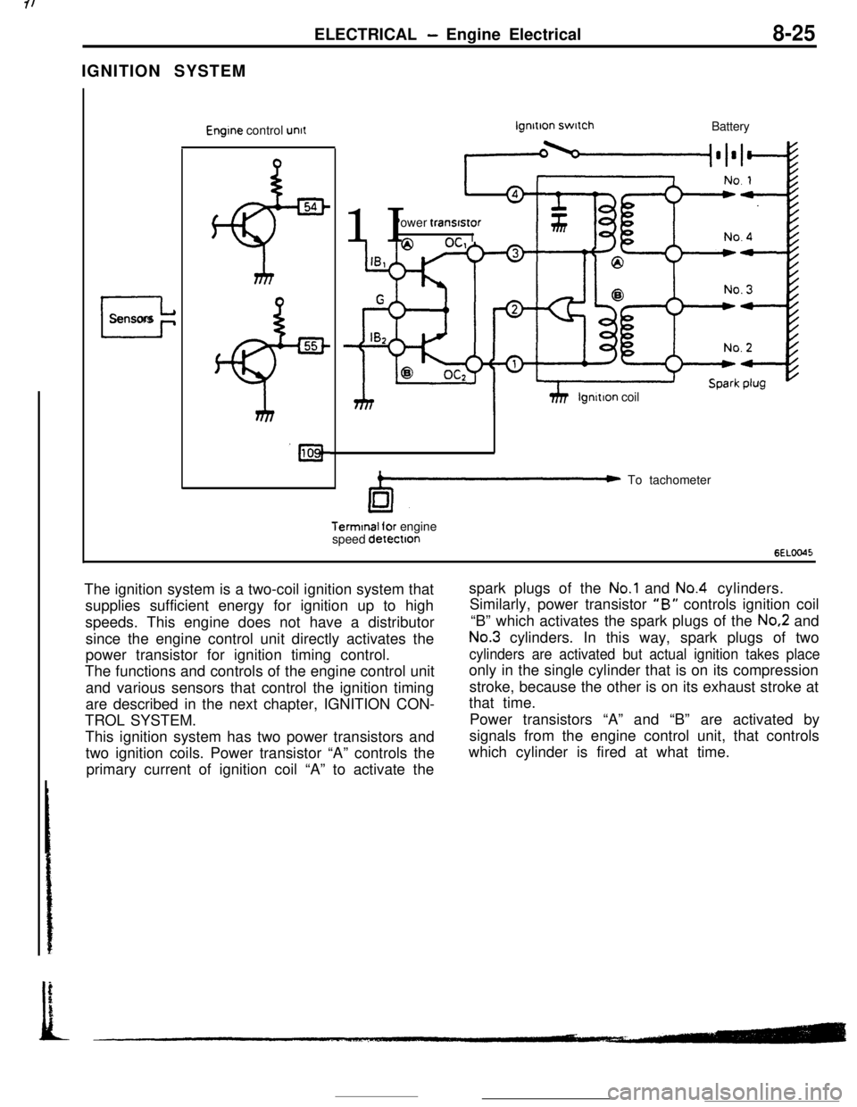
6ELOO45The ignition system is a two-coil ignition system that
supplies sufficient energy for ignition up to high
speeds. This engine does not have a distributor
since the engine control unit directly activates the
power transistor for ignition timing control.
The functions and controls of the engine control unit
and various sensors that control the ignition timing
are described in the next chapter, IGNITION CON-
TROL SYSTEM.
This ignition system has two power transistors and
two ignition coils. Power transistor “A” controls the
primary current of ignition coil “A” to activate thespark plugs of the
No.1 and No.4 cylinders.
Similarly, power transistor
“B” controls ignition coil
“B” which activates the spark plugs of the
No.2 and
No.3 cylinders. In this way, spark plugs of two
cylinders are activated but actual ignition takes placeonly in the single cylinder that is on its compression
stroke, because the other is on its exhaust stroke at
that time.
Power transistors “A” and “B” are activated by
signals from the engine control unit, that controls
which cylinder is fired at what time.
Page 83 of 391
Knocking Control for Turbo Engine OnlyEngine coolant tern.Advance mapperarure correctton
value- Barometric pressurecorrectton
DelonaIlon
sensorI
lgnmon codKnockmg correcllonprimary currenr
v
Knock wbral+onKnockmg LevelDelay anglelgnmon tlmtngdetemon- delermonmon - calculallon - derermmatlon
II
Y
FatlureIdeIeclton
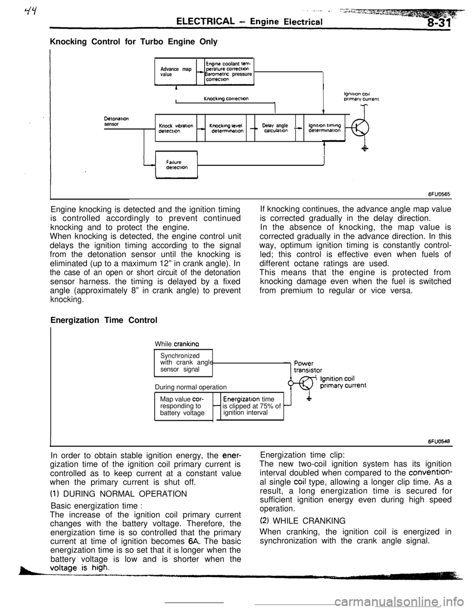
6FUO565Engine knocking is detected and the ignition timing
is controlled accordingly to prevent continued
knocking and to protect the engine.
When knocking is detected, the engine control unit
delays the ignition timing according to the signal
from the detonation sensor until the knocking is
eliminated (up to a maximum 12” in crank angle). In
the case of an open or short circuit of the detonationsensor harness. the timing is delayed by a fixed
angle (approximately 8” in crank angle) to prevent
knocking.Energization Time Control
While
crankinaIf knocking continues, the advance angle map value
is corrected gradually in the delay direction.
In the absence of knocking, the map value is
corrected gradually in the advance direction. In this
way, optimum ignition timing is constantly control-
led; this control is effective even when fuels of
different octane ratings are used.
This means that the engine is protected from
knocking damage even when the fuel is switched
from premium to regular or vice versa.
Synchronizedwith crank angle
sensor signalcDuring normal operation
Map value
cor-Energizatlon time
responding to- is clipped at 75% of
battery voltageignition interval
IIn order to obtain stable ignition energy, the
ener-gization time of the ignition coil primary current is
controlled as to keep current at a constant value
when the primary current is shut off.
(1) DURING NORMAL OPERATION
Basic energization time
:The increase of the ignition coil primary current
changes with the battery voltage. Therefore, the
energization time is so controlled that the primary
current at time of ignition becomes
6A. The basic
energization time is so set that it is longer when the
battery voltage is low and is shorter when the
6FUO548Energization time clip:
The new two-coil ignition system has its ignition
interval doubled when compared to the convention-
al single
coil type, allowing a longer clip time. As a
result, a long energization time is secured for
sufficient ignition energy even during high speed
operation.
(2) WHILE CRANKING
When cranking, the ignition coil is energized in
synchronization with the crank angle signal.
-
Page 98 of 391
ENGINE - Base Engine9-13
VALVE MECHANISM
!
Rocker arm
Exhaustcamshaf
...............
...............
..............................
........................................................
.......................
.......................
.......................
.................................
..........
.........
.........
..........
.........
..........
Exhaust valve
bENOIntake valve6ENOlOOIft
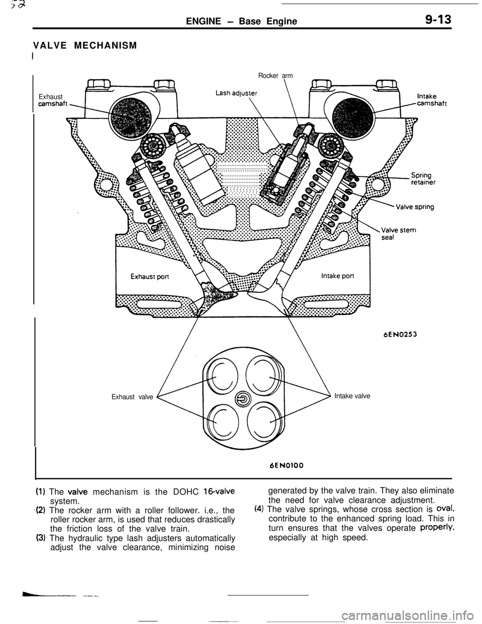
(1) The valve mechanism is the DOHC 16-valvesystem.
.(2) The rocker arm with a roller follower. i.e., the
roller rocker arm, is used that reduces drastically
the friction loss of the valve train.
(3) The hydraulic type lash adjusters automatically
adjust the valve clearance, minimizing noisegenerated by the valve train. They also eliminate
the need for valve clearance adjustment.
(4) The valve springs, whose cross section is oval.contribute to the enhanced spring load. This in
turn ensures that the valves operate properly.
especially at high speed.
- .---..
Page 114 of 391
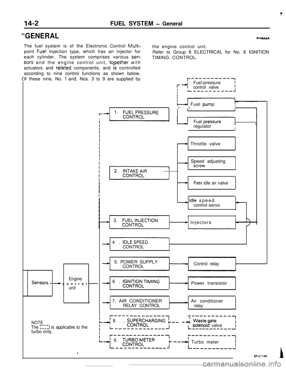
sors and the engine control unit, tooether with
actuators and
related components, and k controlled
according to nine control functions as shown below.
Of these nine, No.
1 and, Nos. 3 to 9 are supplied by
II
EngineSensors - control -unit
r--------‘-1
l--cIFuel-pressureIcontrol valveII
‘4 Fuel DumoI13 I I or-’I
,--c 1. ;;EILT!I;ELSSURE1J
Fuel presJ1regulatorI
- Throttle valve
i
7
_c Speed adjusting
screw
14-2
“GENERALFUEL SYSTEM
- GeneralRl484AB
The fuel system is of the Electronic Control
Multi-point Fuel Injection type, which has an injector forthe engine control unit.
each cylinder. The system comprises various sen-Refer to Group 8 ELECTRICAL for No. 6 IGNITION
TIMING CONTROL.
-Fast idle air valve
- idle speed
control servo-
IrI
- Injectors
- 4. IOLESPEEO
CONTROL
-I5. POWER SUPPLYCONTROLControl relay
-) 6. V$&iRq3NLTIMING- Power transistor
b
-c 7. AIR CONDITIONERRELAY CONTROL- Air conditioner
relay
c-------------Tp----------1
NOTEI
The [‘-,l> is applicable to theI
.-( 8. ZJJ\~RR~LARGING k-- -4 Wastepate
Liturbo only.-----w--------IL solenoid valve--B--------d
Ir-‘---‘---“‘-7c------v--w-1
L’ 9.
-I
‘C;RB;zLETER--A Turbo meterI--------c----J+ L----------a
k’6FU1145
Page 123 of 391
FUEL SYSTEM -Fuel Supply and Fuel Pressure Control
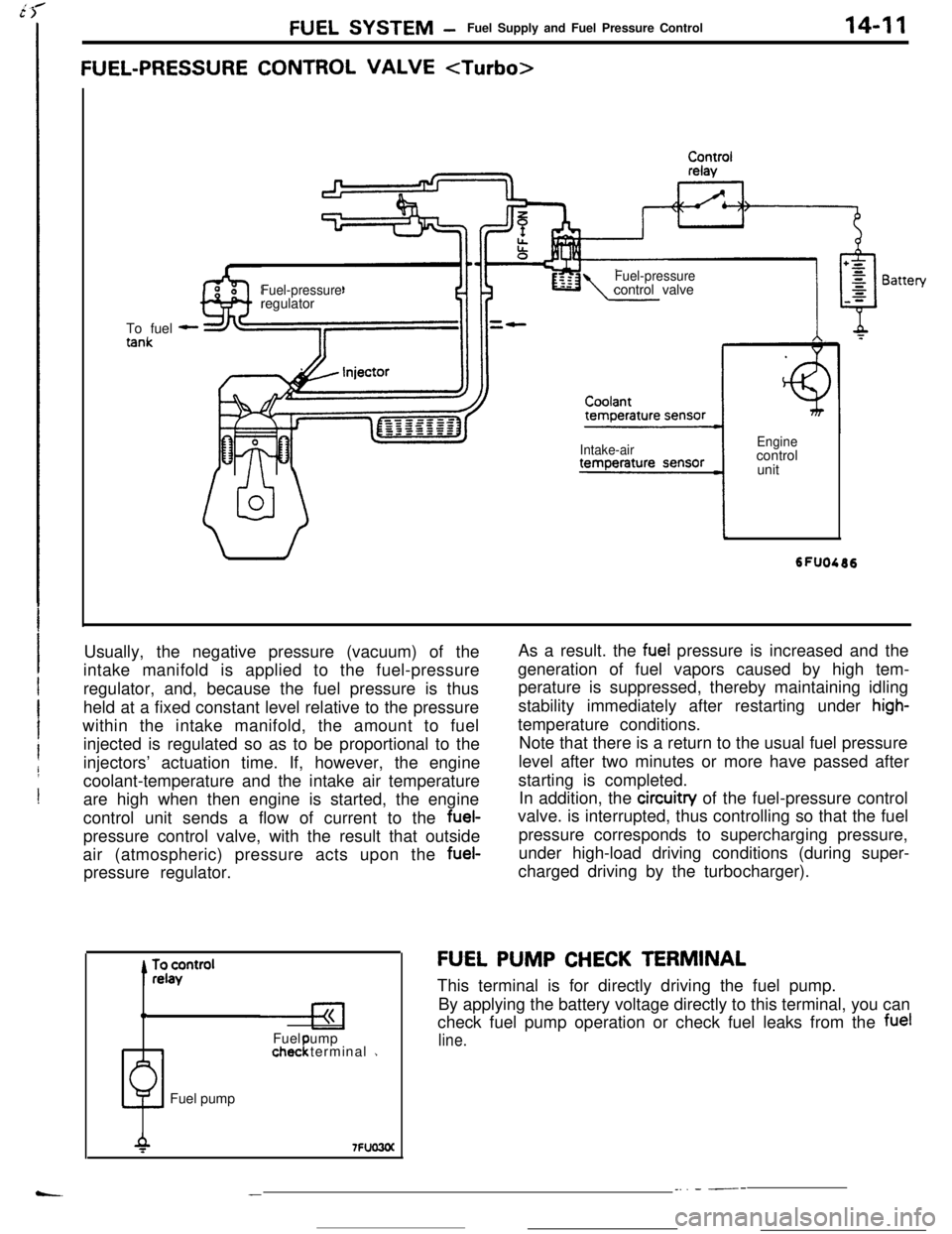
FUEL-PRESSURE CONTROL VALVE
14-11To fuel
-
Fuel-pressureregulatorFuel-pressurecontrol valve
Intake-airEnginecontrol
unit
Usually, the negative pressure (vacuum) of the
intake manifold is applied to the fuel-pressure
regulator, and, because the fuel pressure is thus
held at a fixed constant level relative to the pressure
within the intake manifold, the amount to fuel
injected is regulated so as to be proportional to the
injectors’ actuation time. If, however, the engine
coolant-temperature and the intake air temperature
are high when then engine is started, the engine
control unit sends a flow of current to the fuel-
pressure control valve, with the result that outside
air (atmospheric) pressure acts upon the fuel-
pressure regulator.
0Fuel ump
1chec terminal 1!Fuel pumpAs a result. the
fuel pressure is increased and the
generation of fuel vapors caused by high tem-
perature is suppressed, thereby maintaining idling
stability immediately after restarting under
high-temperature conditions.
Note that there is a return to the usual fuel pressure
level after two minutes or more have passed after
starting is completed.
In addition, the circuitry of the fuel-pressure control
valve. is interrupted, thus controlling so that the fuel
pressure corresponds to supercharging pressure,
under high-load driving conditions (during super-
charged driving by the turbocharger).
FU,EL PUMP CHECK TERMINAL
This terminal is for directly driving the fuel pump.
By applying the battery voltage directly to this terminal, you can
check fuel pump operation or check fuel leaks from the
fuel
line.
__. - ---