rod MITSUBISHI ECLIPSE 1990 User Guide
[x] Cancel search | Manufacturer: MITSUBISHI, Model Year: 1990, Model line: ECLIPSE, Model: MITSUBISHI ECLIPSE 1990Pages: 391, PDF Size: 15.27 MB
Page 240 of 391
_-
21-16AUTOMATIC TRANSAXLE - General InformationAUTOMATIC
TRANSAXLE
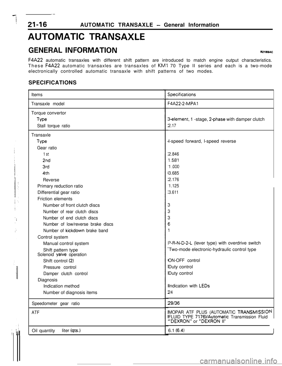
GENERAL INFQRMATIONRzlBBACF4A22 automatic transaxles with different shift pattern are introduced to match engine output characteristics.
These F4A22 automatic transaxles are transaxles of KM1 70 Type II series and each is a two-mode
electronically controlled automatic transaxle with shift patterns of two modes.
SPECIFICATIONS
Items
Transaxle modelTorque convertor
Me
Stall torque ratio
TransaxleType
Gear ratio
1 St
2nd
3rd4th
ReversePrimary reduction ratio
Differential gear ratio
Friction elements
Number of front clutch discs
Number of rear clutch discs
Number of end clutch discs
Number of low/reverse brake discs
Number of
kickdown brake bandControl system
Manual control system
Shift pattern type
Solenoid yalve operationShift control
(2)
Pressure control
Damper clutch controlDiagnosis
Indication method
Number of diagnosis items
Speedometer gear ratio
ATFOil quantityliter
(qts.)
Specifications-4A22-2-MPAl3element, 1 -stage,
2-phase with damper clutch
2.17l-speed forward, l-speed reverse
2.846
1.581
1
.ooo
3.685
2.176
1.125
3.611V&N-D-2-L (lever type) with overdrive switch
Two-mode electronic-hydraulic control type
ON-OFF controlDuty control
Duty control
Indication with
LEDs
24
29136
MOPAR ATF PLUS (AUTOMATIC TRANSMISSIOI
FLUID TYPE 7176VAutomatic Transmission Fluid“DEXRON” or “DEXRON II”
\I6.1
(6.4)J
Page 252 of 391
.-
I
21-28AUTOMATIC TRANSAXLE - Transaxle Mechanism
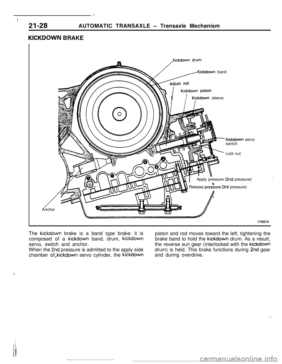
KICKDOWN BRAKE
/Kickdown band
r\\ IKickdown sleeve
- Kickdown servo
switch
;‘- Locknut
Apply pressure
(2nd pressure)
1 Release pre&re (3rd pressure)I,
/ --Anchor
1750219The kickdown brake is a band type brake; it is
piston and rod moves toward the left, tightening the
composed of a kickdown band, drum, kickdownbrake band to hold the kickdown drum. As a result,
servo, switch and anchor.the reverse sun gear (interlocked with the kickdown
When the
2nd pressure is admitted to the apply sidedrum) is held. This brake functions during 2nd gear
chamber of,kickdown servo cylinder, the kickdownand during overdrive.
Page 255 of 391
iAUTOMATIC TRANSAXLE
- Transaxle Mechanism
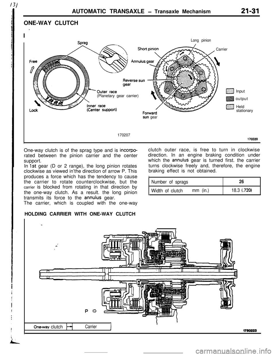
ONE-WAY CLUTCH
I
’
21-31
Long pinion(Planetary gear carrier)
CarrierInput
output
Held
stationary
sun gear
170207170320One-way clutch is of the sprag type and is
incorpo-rated between the pinion carrier and the center
support.
In
1st gear (D or 2 range), the long pinion rotates
clockwise as viewed in’the direction of arrow P. This
produces a force which has the tendency to cause
the carrier to rotate counterclockwise, but the
carrier is blocked from rotating in that direction by
the one-way clutch. As a result. the long pinion
transmits its force to the
annulus gear.
The carrier, which is coupled with the one-wayclutch outer race, is free to turn in clockwise
direction. In an engine braking condition under
which the
annulus gear is turned first. the carrier
turns clockwise freely and, therefore, the engine
braking effect is not obtained.
INumber of sprags26
Width of clutchmm (in.)18.3 (720)HOLDING CARRIER WITH ONE-WAY CLUTCH
P 0
On-y clutchI
\Carrierl7so223
Page 263 of 391
AUTOMATIC TRANSAXLE - Transaxle Mechanism
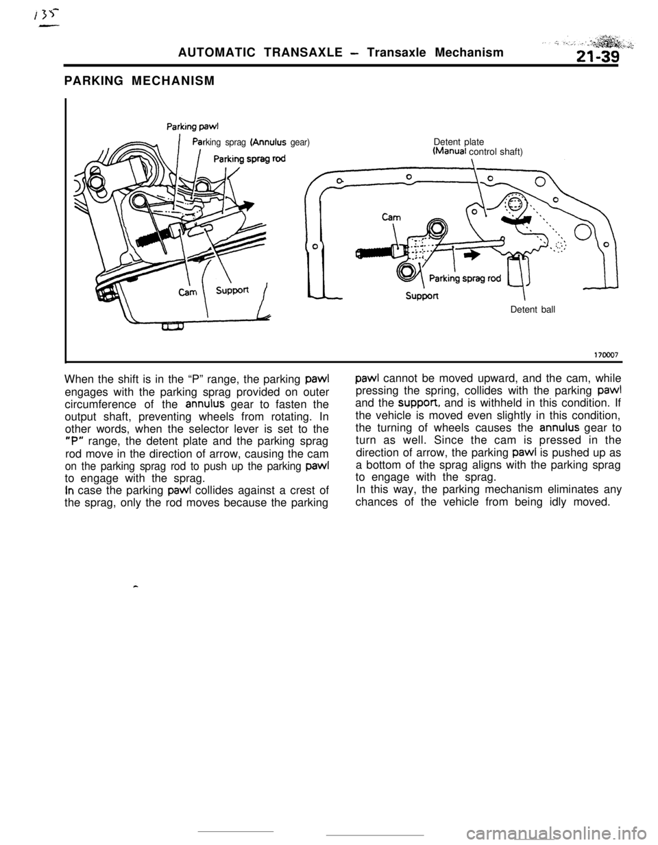
PARKING MECHANISM
rking sprag (Annulus gear)Detent plateWanual control shaft)
Detent ball
17ooo7When the shift is in the “P” range, the parking pawl
paw1 cannot be moved upward, and the cam, while
engages with the parking sprag provided on outerpressing the spring, collides with the parking
paw1circumference of the
annulus gear to fasten theand the suppon, and is withheld in this condition. If
output shaft, preventing wheels from rotating. Inthe vehicle is moved even slightly in this condition,
other words, when the selector lever is set to thethe turning of wheels causes the
annulus gear to
“P” range, the detent plate and the parking spragturn as well. Since the cam is pressed in the
rod move in the direction of arrow, causing the camdirection of arrow, the parking pawl is pushed up as
on the parking sprag rod to push up the parking paw1a bottom of the sprag aligns with the parking sprag
to engage with the sprag.to engage with the sprag.
In case the parking paw1 collides against a crest of
the sprag, only the rod moves because the parkingIn this way, the parking mechanism eliminates any
chances of the vehicle from being idly moved.
Page 269 of 391
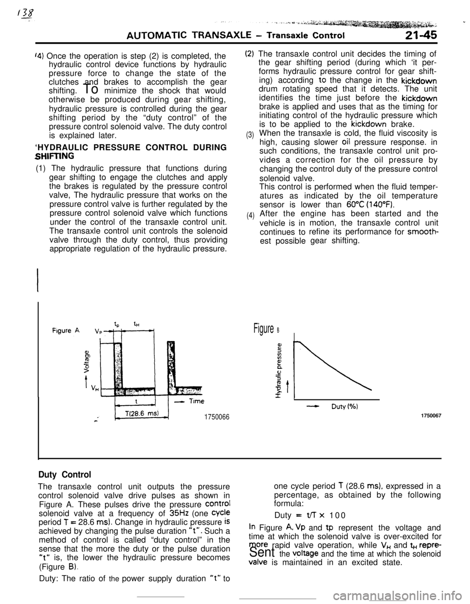
‘4) Once the operation is step (2) is completed, the
hydraulic control device functions by hydraulic
pressure force to change the state of the
clutches and brakes to accomplish the gear
shifting. To minimize the shock that would
otherwise be produced during gear shifting,
hydraulic pressure is controlled during the gear
shifting period by the “duty control” of the
pressure control solenoid valve. The duty control
is explained later.
‘HYDRAULIC PRESSURE CONTROL DURING
SHFIING(1) The hydraulic pressure that functions during
gear shifting to engage the clutches and apply
the brakes is regulated by the pressure control
valve, The hydraulic pressure that works on the
pressure control valve is further regulated by the
pressure control solenoid valve which functions
under the control of the transaxle control unit.
The transaxle control unit controls the solenoid
valve through the duty control, thus providing
appropriate regulation of the hydraulic pressure.
(2)
(3)
(4)The transaxle control unit decides the timing of
the gear shifting period (during which ‘it per-
forms hydraulic pressure control for gear shift-
ing) according to the change in the kickdown
drum rotating speed that it detects. The unit
identifies the time just before the kickdown
brake is applied and uses that as the timing for
initiating control of the hydraulic pressure which
is to be applied to the kickdown brake.
When the transaxle is cold, the fluid viscosity is
high, causing slower oil pressure response. in
such conditions, the transaxle control unit pro-
vides a correction for the oil pressure by
changing the control duty of the pressure control
solenoid valve.
This control is performed when the fluid temper-
atures as indicated by the oil temperature
sensor is lower than
60°C (140°F).After the engine has been started and the
vehicle is inmotion, the transaxle
continues torefine its performance
est possiblegear shifting.control unit
for smooth-
tHFigure B
- Duty(%)
17500661750067
Duty ControlThe transaxle control unit outputs the pressureone cycle period
T (28.6 ms), expressed in a
control solenoid valve drive pulses as shown inpercentage, as obtained by the following
formula:
Figure A. These pulses drive the pressure
COrmIsolenoid valve at a frequency of
35Hz (one Cycleperiod
T = 28.6 ms). Change in hydraulic pressure iSDuty =t/-r x 100
achieved by changing the pulse duration
“t”. Such aIn Figure A, Vp and tp represent the voltage and
method of control is called “duty control” in thetime at which the solenoid valve is over-excited for
sense that the more the duty or the pulse duration
more rapid valve operation, while V,, and t+., repre-
“t” is, the lower the hydraulic pressure becomesSent the v,oltage and the time at which the solenoid(Figure
B).Valve is maintained in an excited state.
Duty: The ratio of the power supply duration
“t” to
Page 271 of 391
AUTOMATIC TRANSAXLE - Transaxle Control21-47
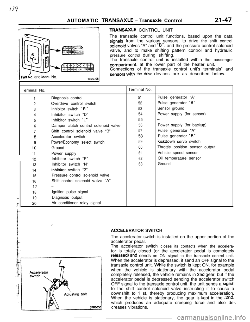
+TFWNSAXLE CONTROL UNIT
Part b!o. and Ident. No.17504The transaxle control unit functions, based upon the data
signals from the various sensors, to drive the shift controlsolenoid valves “A” and
“B”, and the pressure control solenoid
valve, and to make shifting pattern control and hydraulic
pressure control during shifting.
The transaxle control unit is installed within the passengercompartment, at the lower part of the heater unit.
Connections of the transaxle control unit’s terminals” and
sensors with the drive devices are as described below.
Terminal No.Terminal No.
1Diagnosis control51Pulse generator “A”
2Overdrive control switch52Pulse generator “B”
3Inhibitor switch e R U53Sensor ground
4Inhibitor switch “D”
54Power supply (for sensor)
5Inhibitor switch “L”55 -
6Damper clutch control solenoid valve56Power supply (for backup)
7Shift control solenoid valve “B”57Pulse generator “A”
8Accelerator switch58Pulse generator “B”
9Power/Economy select switch59Kickdown servo switch
10Ground60Throttle position sensor output
11Power supply61Vehicle speed sensor
12Inhibitor switch “P”62Oil temperature sensor
13Inhibitor switch “N”63Ground
14inhibitor switch “2”
15Pressure control solenoid valve
16Shift control solenoid valve “A”
17
-
18Ignition pulse signal
19Diagnosis output
20Air conditioner relay signal
rACCELERATOR SWITCH
The accelerator switch is installed on the upper portion of the
accelerator pedal.
The accelerator switch closes its contacts when the accelera-
tor is totally closed (or the accelerator pedal is completelyreieasedj‘and sends on ON signal to the transaxle control unit.
When the accelerator is depressed, it send an OFF signal to the
transaxle control unit. Whiie the switch is kept ON, for example
when the vehicle is stationary with the accelerator pedal
completely released, the vehicle remains in
2nd gear, but if the
accelerator pedal is depressed sending the accelerator switch
OFF signal to the transaxle control unit, the unit sends a signal
to the shift control solenoid valve instructing it to cause a
downshift to 1 st, thereby producing maximum acceleration.
When the vehicle is stationary, the gear is kept in the .2nd,
which produces an adequate creeping force and also de-.
creases vibrations.
Page 284 of 391
21-60AUTOMATIC TRANSAXLE - Transaxle Control
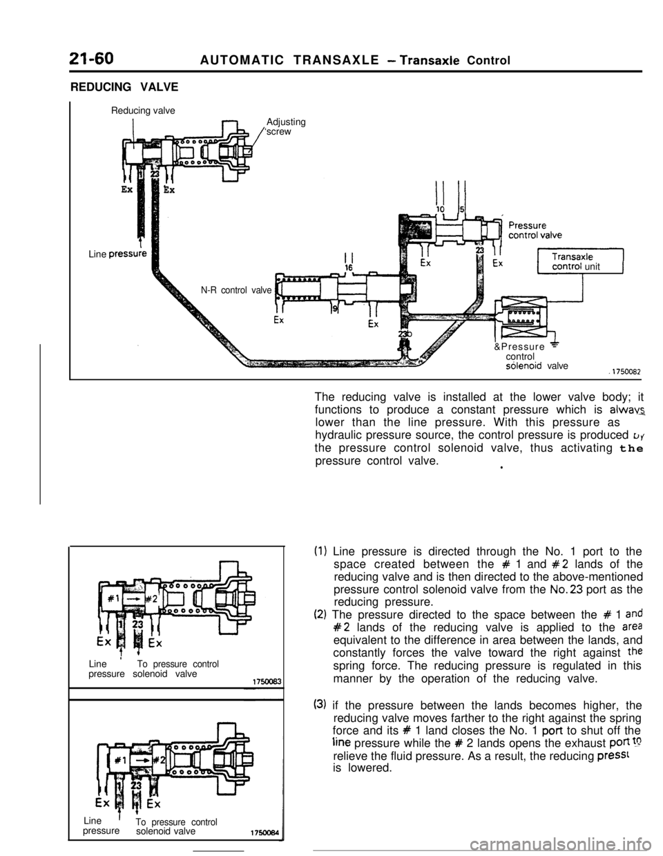
REDUCING VALVE
Reducing valve
ExLine
press1
ExAdjusting
‘screw
N-R control valveunit
J&Pressure
+controlsblenoid valve.1750082
Line
’To pressure controlpressure solenoid valve
Line
’To pressure controlpressure
solenoid valve175ocs4The reducing valve is installed at the lower valve body; it
functions to produce a constant pressure which is
alwav2lower than the line pressure. With this pressure as
hydraulic pressure source, the control pressure is produced
LJYthe pressure control solenoid valve, thus activating the
pressure control valve.
l
(1
(2
) Line pressure is directed through the No. 1 port to the
space created between the
# 1 and #2 lands of the
reducing valve and is then directed to the above-mentioned
pressure control solenoid valve from the No.23 port as the
reducing pressure.
:) The pressure directed to the space between the # 1 and
#2 lands of the reducing valve is applied to the areaequivalent to the difference in area between the lands, and
constantly forces the valve toward the right against
thespring force. The reducing pressure is regulated in this
manner by the operation of the reducing valve.
(3) if the pressure between the lands becomes higher, the
reducing valve moves farther to the right against the spring
force and its
# 1 land closes the No. 1 port to shut off theline pressure while the
# 2 lands opens the exhaust poti !grelieve the fluid pressure. As a result, the reducing
press1is lowered.
Page 294 of 391
21-72AUTOMATIC TRANSAXLE - Transaxle Control
_. --.
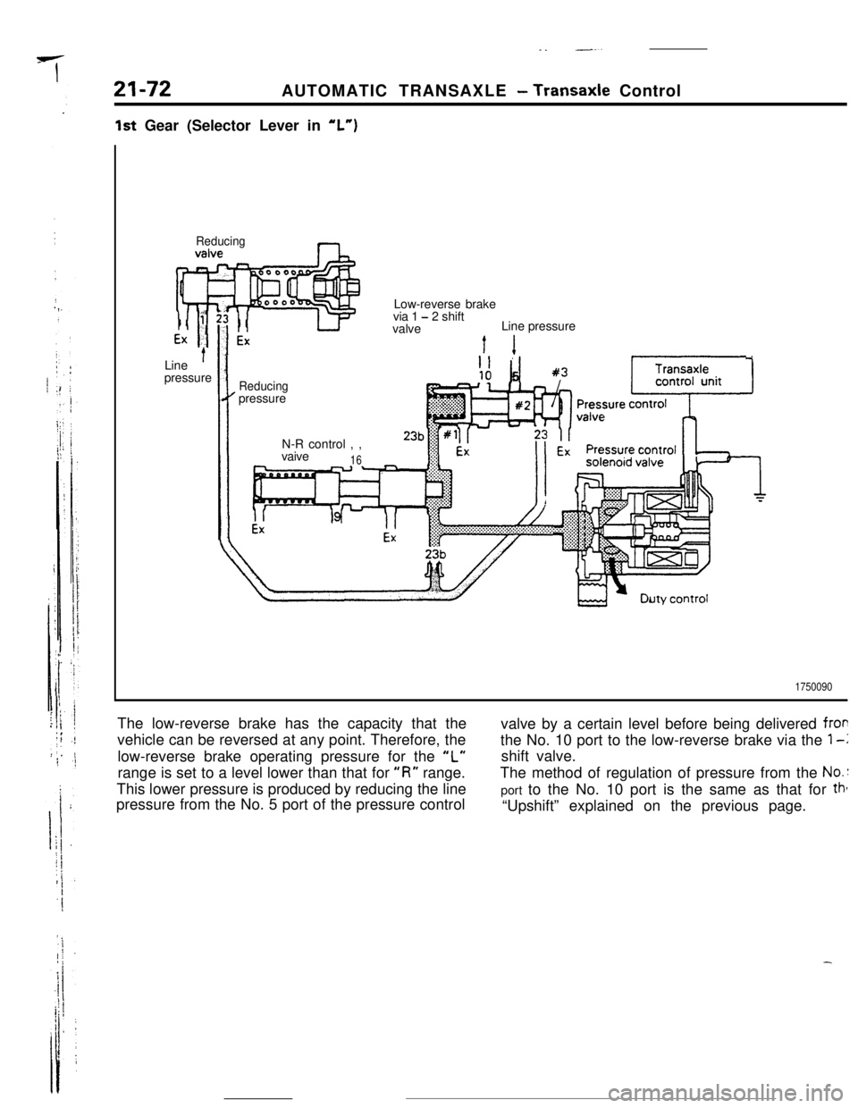
1st Gear (Selector Lever in “L”)
ReducingnLow-reverse brake
via 1
- 2 shift
valveLine pressure
Line
’pressureI1
Reducingpressure
N-R control , ,
vaive
16--.. -
1750090The low-reverse brake has the capacity that the
vehicle can be reversed at any point. Therefore, the
low-reverse brake operating pressure for the
“L”range is set to a level lower than that for
“I?” range.
This lower pressure is produced by reducing the line
pressure from the No. 5 port of the pressure controlvalve by a certain level before being delivered
frorthe No. 10 port to the low-reverse brake via the
1-lshift valve.
The method of regulation of pressure from the
No.:port to the No. 10 port is the same as that for
tht“Upshift” explained on the previous page.
Page 321 of 391
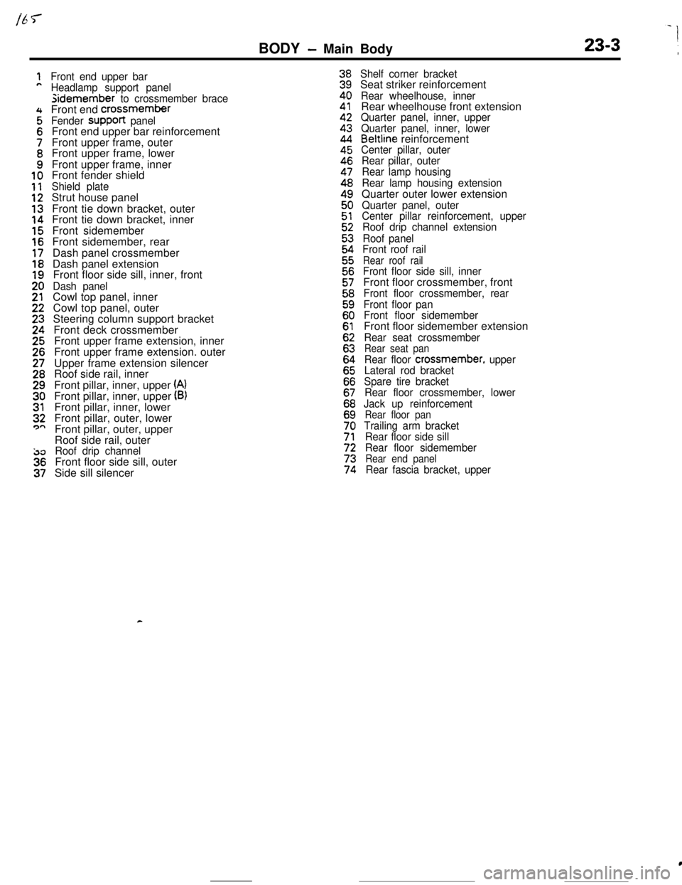
BODY - Main Body23-3 \
Front end upper bar
Headlamp support panelsidemember
to crossmember braceFront end crossmember
Fender suppoR panelFront end upper bar reinforcement
Front upper frame, outer
Front upper frame, lower
Front upper frame, inner
Front fender shield
Shield plateStrut house panel
Front tie down bracket, outer
Front tie down bracket, inner
Front sidemember
Front sidemember, rear
Dash panel crossmember
Dash panel extension
Front floor side sill, inner, front
Dash panelCowl top panel, inner
Cowl top panel, outer
Steering column support bracket
Front deck crossmember
Front upper frame extension, inner
Front upper frame extension. outer
Upper frame extension silencer
Roof side rail, inner
Front pillar, inner, upper
(A)Front pillar, inner, upper (B)Front pillar, inner, lower
Front pillar, outer, lower
Front pillar, outer, upper
Roof side rail, outer
Roof drip channelFront floor side sill, outer
Side sill silencer
Shelf corner bracketSeat striker reinforcement
Rear wheelhouse, innerRear wheelhouse front extension
Quarter panel, inner, upper
Quarter panel, inner, lower
Beltline reinforcementCenter pillar, outer
Rear pillar, outer
Rear lamp housing
Rear lamp housing extensionQuarter outer lower extension
Quarter panel, outer
Center pillar reinforcement, upper
Roof drip channel extension
Roof panel
Front roof rail
Rear roof railFront floor side sill, innerFront floor crossmember, front
Front floor crossmember, rear
Front floor pan
Front floor sidememberFront floor sidemember extension
Rear seat crossmemberRear seat panRear floor crossmember, upper
Lateral rod bracket
Spare tire bracket
Rear floor crossmember, lower
Jack up reinforcement
Rear floor panTrailing arm bracket
Rear floor side sill
Rear floor sidemember
Rear end panelRear fascia bracket, upper
c
c
Page 325 of 391
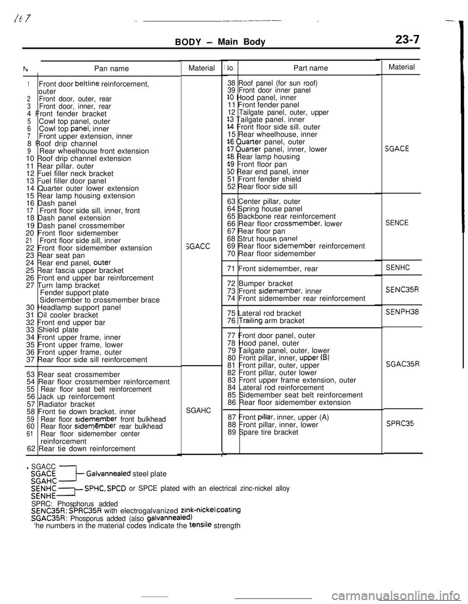
/E 7_.___-__----_BODY
- Main Body23-7Material
IhPan name
1Front door beltline reinforcement,
outer
2Front door, outer, rear3Front door, inner, rear4 Front fender bracket
5Cowl top panel, outer6Cowl top panel. inner7Front upper extension, inner
8 Roof drip channel
9Rear wheelhouse front extension
10 Roof drip channel extension
11 Rear pillar. outer
12 Fuel filler neck bracket
13 Fuel filler door panel
14 Quarter outer lower extension
15 Rear lamp housing extension
16 Dash panel
17Front floor side sill. inner, front
18 Dash panel extension
19 Dash panel crossmember
20 Front floor sidemember
21Front floor side sill, inner
22 Front floor sidemember extension
23 Rear seat pan
24 Rear end panel,
outer25 Rear fascia upper bracket
26 Front end upper bar reinforcement
27 Turn lamp bracket
Fender support plate
Sidemember to crossmember brace
30 Headlamp support panel
31 Oil cooler bracket
32 Front end upper bar
33 Shield plate
34 Front upper frame, inner
35 Front upper frame, lower
36 Front upper frame, outer
37 Rear floor side sill reinforcement
SGACCIO.Part name
38 Roof panel (for sun roof)
39 Front door inner panel
10 Hood panel, inner
11 Front fender panel
12 Tailgate panel, outer, upper13 Tailgate panel. inner14 Front floor side sill. outer
15 Rear wheelhouse, inner
16 Quaner panel, outer17 Quarter panel, inner, lower18 Rear lamp housing
19 Front floor pan50 Rear end panel, inner
51 Front fender shield
52 Rear floor side sill
63 Center pillar, outer
64 Spring house panel
65 Backbone rear reinforcement
66 Rear floor
crossmember. lower
67 Rear floor pan
68 Strut house panel
69 Rear floor sidemember reinforcement
70 Rear floor sidemember
71 Front sidemember, rear
72 Bumper bracket
73 Front
sidemember. inner
74 Front sidemember rear reinforcement
75 Lateral rod bracket
76
ITrailing arm bracket
53 Rear seat crossmember
54 Rear floor crossmember reinforcement
55Rear floor seat belt reinforcement56 Jack up reinforcement
57 Radiator bracket
58 Front tie down bracket. inner
59Rear floor sidemember front bulkhead
60Rear floor sidemember rear bulkhead61Rear floor sidemember centerreinforcement77 Front door panel, outer
78 Hood panel, outer
79 Tailgate panel, outer, lower
80 Front pillar, inner, upper(B)
81 Front pillar, outer, upper
82 Front pillar, outer lower
83 Front upper frame extension, outer
84 Lateral rod reinforcement
85 Sidemember seat belt reinforcement
86 Rear floor sidemember extension
SGAHC87 Front pillar, inner, upper (A)
88 Front pillar, inner, lower
89 Spare tire bracket
62 Rear tie down reinforcement
i
l SGACC%;k; 3 Gaivannealed steel plate
;E;;E I SPHC, SPCD or SPCE plated with an electrical zinc-nickel alloy
SPRC: Phosphorus added
SENC35R: SPRC35R with electrogalvanized zink-nickel CoatingSGAC35R:
Phosporus added (also galvannealed)‘he numbers in the material codes indicate the tensile strengthMaterial
SGACE
SENCE
SENHC
SENC35R
SENPH38
SGAC35R
SPRC35