MITSUBISHI ECLIPSE 1990 Service Manual
ECLIPSE 1990
MITSUBISHI
MITSUBISHI
https://www.carmanualsonline.info/img/19/57103/w960_57103-0.png
MITSUBISHI ECLIPSE 1990 Service Manual
Page 3 of 391
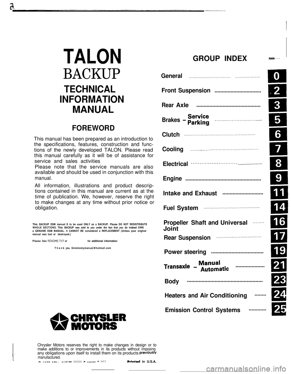
TALON
BACKUP
README.N or for additional information
PreViOUSlVmanufactured.a *-a- .I._..-1-L,.* _____ #Q ^_^__ l L.-Orintul in U.S.A.
GROUP INDEXROSA. - -
General. . . . . . . . . . . . . . . . . . . . . . . . . . . . . .. . . . . . . . . . . . . . . . . .
Front Suspensio n................................
.
Brakes - Eir$rii. . . . . . . . . . . . . . . . . . . . . . . . . . ..s...
Clutch. . . . . . . . . . . . . . . . . . . . . . . . . . . . . . . . . . . . . . . . . . . . . . . . . . . .
Cooling. . . . . . :. . . . .. . . . . . . . . . . . . . . . . . . . . . . . . . . . . . . . . . . .
Electrical. . . . . . . . . . . . . . . . . . . . . . . . . . . ..-..................
Engine....................................................
. . . . . . . . . . . . . . . . . . . . . . . . . . . . . . . . . . . . . . . .
Propeller Shaft and Universal. . . . . . . .
ml
. . . . . . . . . . . . . . . . . . . . . . . . . . . . . . . .
Power steeringCD
ManualTransaxl e - Automatic....................
m
Bodym
Heaters and Air ConditioningRI
A
Emission Control Systems
Page 17 of 391
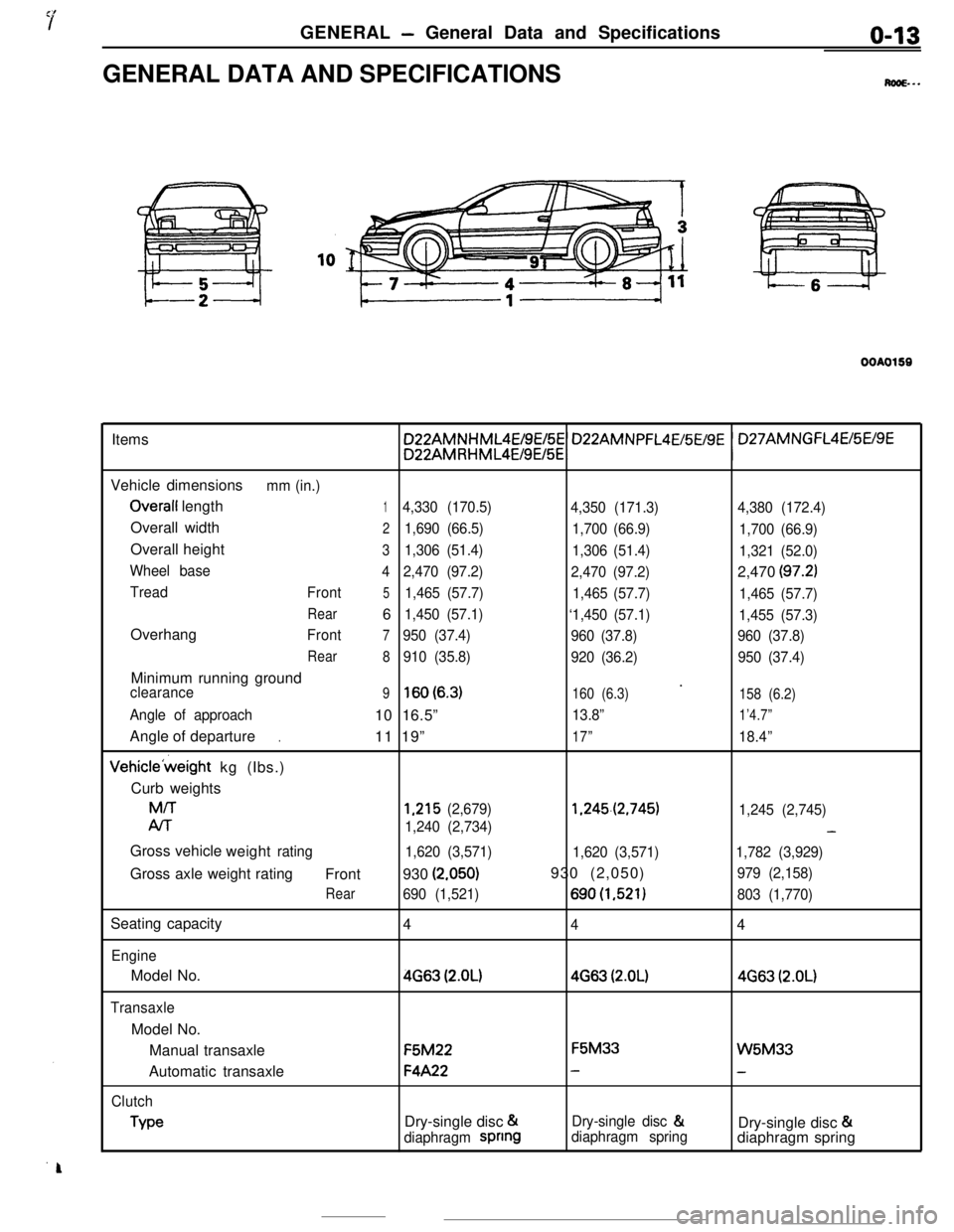
GENERAL - General Data and Specificationso-13GENERAL DATA AND SPECIFICATIONS
M...
OOAO159Items
Vehicle dimensions
mm (in.)
Overall length14,330 (170.5)
4,350 (171.3)4,380 (172.4)Overall width
21,690 (66.5)
1,700 (66.9)
1,700 (66.9)Overall height
31,306 (51.4)
1,306 (51.4)
1,321 (52.0)
Wheel base
42,470 (97.2)
2,470 (97.2)2,470
(97.2)
Tread
Front51,465 (57.7)
1,465 (57.7)
1,465 (57.7)
Rear61,450 (57.1)
‘1,450 (57.1)
1,455 (57.3)Overhang
Front7950 (37.4)
960 (37.8)960 (37.8)
Rear
8910 (35.8)
920 (36.2)950 (37.4)Minimum running ground
’clearance9lsO(6.3)160 (6.3)
158 (6.2)
Angle of approach10 16.5”13.8”1’4.7”Angle of departure
11 19”
17”18.4”.Vehicle’weight kg (Ibs.)
Curb weightsM/T
1,215 (2,679)1.245.(2,745)
1,245 (2,745)
Al-r
1,240 (2,734)-Gross vehicle
weight
rating
1,620 (3,571)
1,620 (3,571)1,782 (3,929)Gross axle weight rating
Front930
(2.050)930 (2,050)979 (2,158)
Rear690 (1,521)690(1,521)803 (1,770)Seating capacity
4
44
EngineModel No.
4663 (2.OL)4663 (2.OL)4663 (2.OL)
TransaxleModel No.
Manual transaxleF5M22F5M33
W5M33Automatic transaxle
F4A22--
Clutch
TypeDry-single disc &Dry-single disc &
Dry-single disc &
diaphragm spnngdiaphragm springdiaphragm spring
Page 44 of 391
Page 45 of 391
.__...e-
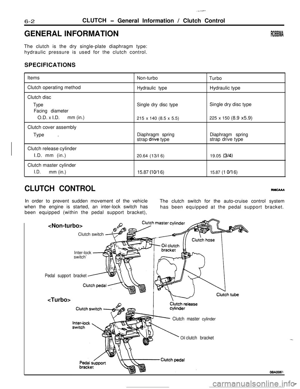
6-2
drove typeDiaphragm spring
(314)
15.87 (10/l 6) 15.87 (1 O/l 6)
CLUTCH CONTROL
Page 46 of 391
-. ..- ,..__ _. I-., . . . . -. . “-Ix.. ...~‘,.;;&;,-*~;
CLUTCH- Clutch Control6-3
-
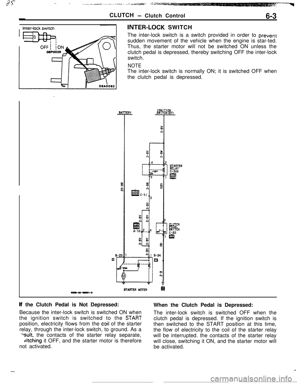
Inter-lock switchINTER-LOCK SWITCH
The inter-lock switch is a switch provided in order to prevent
sudden movement of the vehicle when the engine is star-ted.
BTAFTER YCTER
If the Clutch Pedal is Not Depressed:
Because the inter-lock switch is switched ON when
STABT
position, electricity flows from the cloil of the starter
relay, through the inter-lock switch, to ground. As a
?sult, the contacts of the starter relay separate,
vitching it OFF, and the starter motor is therefore
not activated.
Page 49 of 391
7’
IF---I ’,,,.1:.;: ~&~~Lx.*.*. .Ihcin.*L-..r-‘- --a’ -.-
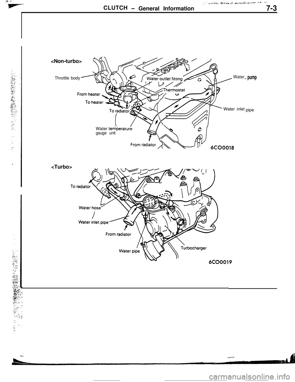
CLUTCH- General Information 7-3
I
Throttle body
tedperat&gauge unit
From raclw6cOO0,8
. pump
Page 56 of 391
_--
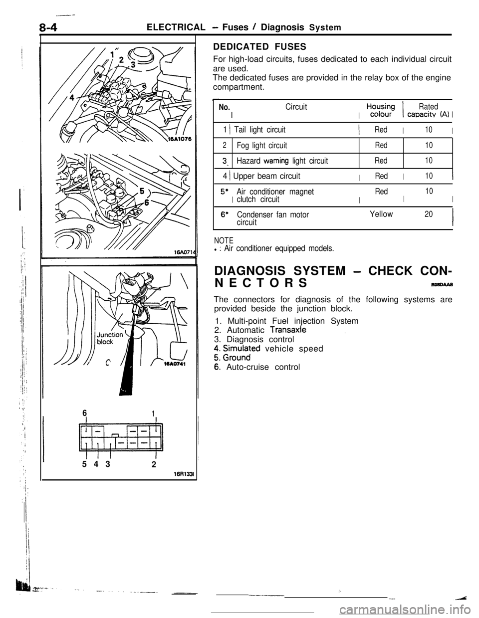
8-4ELECTRICAL - Fuses / Diagnosis System
61543
2
16R133lDEDICATED FUSES
For high-load circuits, fuses dedicated to each individual circuit
are used.
The dedicated fuses are provided in the relay box of the engine
compartment.
No.
I
Circuit
I
H,“d;;-;I
Rated
canacitv (A)I
1 1 Tail light circuitIRedI10I
2Fog light circuitRed10
3,.Hazard warning light circuitRed10
4 ) Upper beam circuitIRedI10I
5’
I
Air conditioner magnet
I
Red
I
10
clutch circuitI
6’Condenser fan motorYellow20
circuitI
NOTEl : Air conditioner equipped models.DIAGNOSIS SYSTEM
- CHECK CON-
NECTORS
nmcwaBThe connectors for diagnosis of the following systems are
provided beside the junction block.
1. Multi-point Fuel injection System
2. Automatic
Transaxle.3. Diagnosis control
z. grm.rlnaFd vehicle speed
6: Auto-cruise control
:..--.-__-.
Page 59 of 391
ELECTRICAL -Relavs, Control Units and Sensors
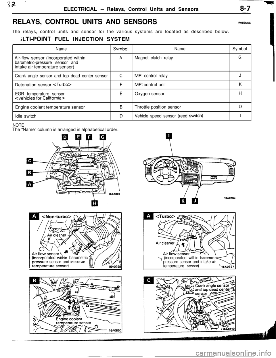
RELAYS, CONTROL UNITS AND SENSORSROBEAACThe relays, control units and sensor for the various systems are located as described below.
.ILTI-POINT FUEL INJECTION SYSTEM
NameSymbolNameSymbolAir-flow sensor (incorporated within
AMagnet clutch relayG
barometric-pressure sensor andintake air temperature sensor)
Crank angle sensor and top dead center sensorCMPI control relayJDetonation sensor
FMPI control unitK
EGR temperature sensorEOxygen sensorH
Engine coolant temperature sensor
BThrottle position sensorDIdle switch
DVehicle speed sensor (reed switch)I
NOTEThe “Name” column is arranged in alphabetical order.
orated within barometric
re sensor and Intake arr7 (incorporated within barometnc kpressure sensor and intake arrtemperature sensor)-4L 1mo721
Page 63 of 391
1ELECTRICAL
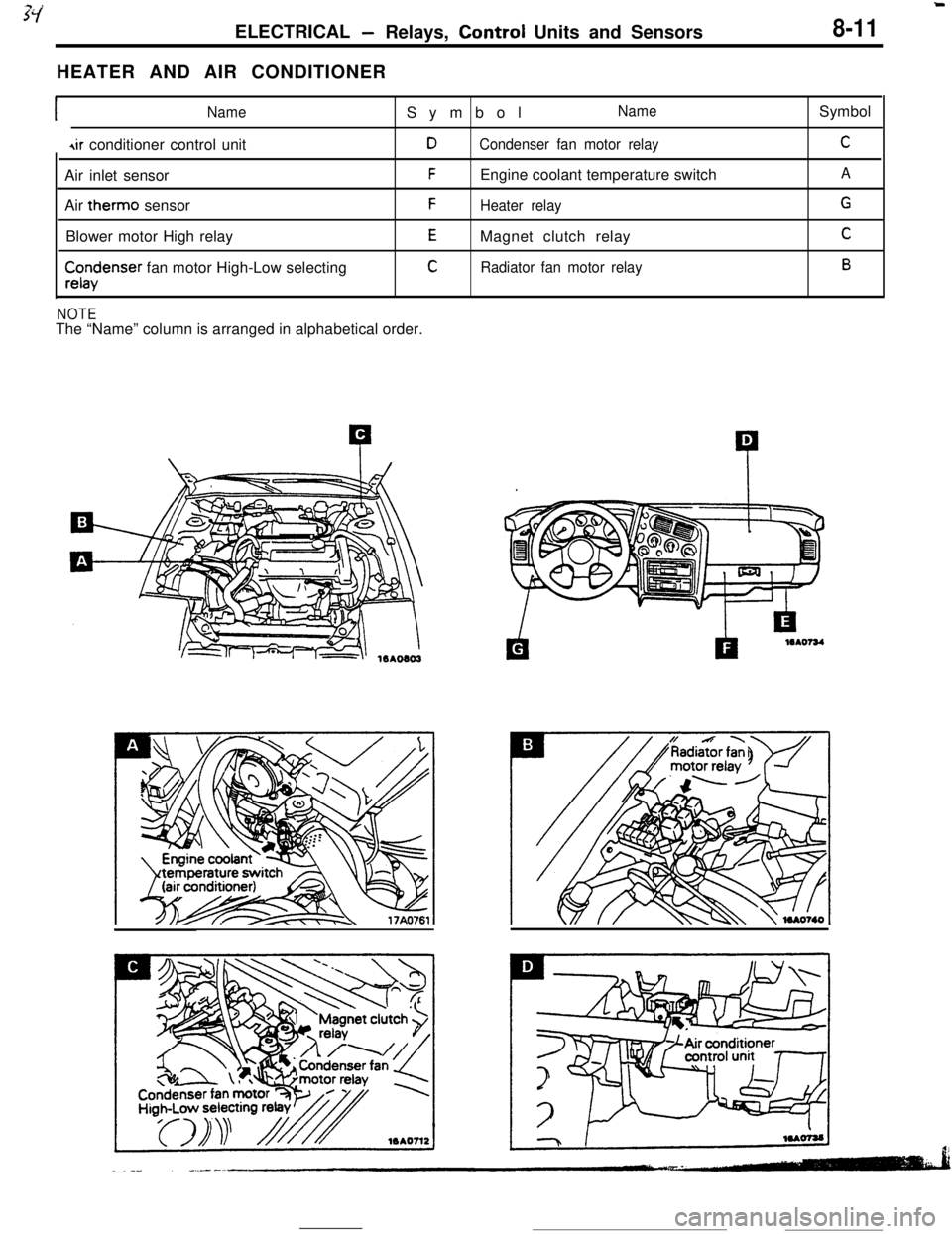
-Relays, Control Units and Sensors8-11HEATER AND AIR CONDITIONER
INameSymbolName
4ir conditioner control unitDCondenser fan motor relayAir inlet sensor
FEngine coolant temperature switch
Air therm0 sensor
FHeater relayBlower motor High relay
EMagnet clutch relay
$x$enser fan motor High-Low selectingCRadiator fan motor relay
NOTEThe “Name” column is arranged in alphabetical order.Symbol
C
A
G
C
B
Page 76 of 391
.-
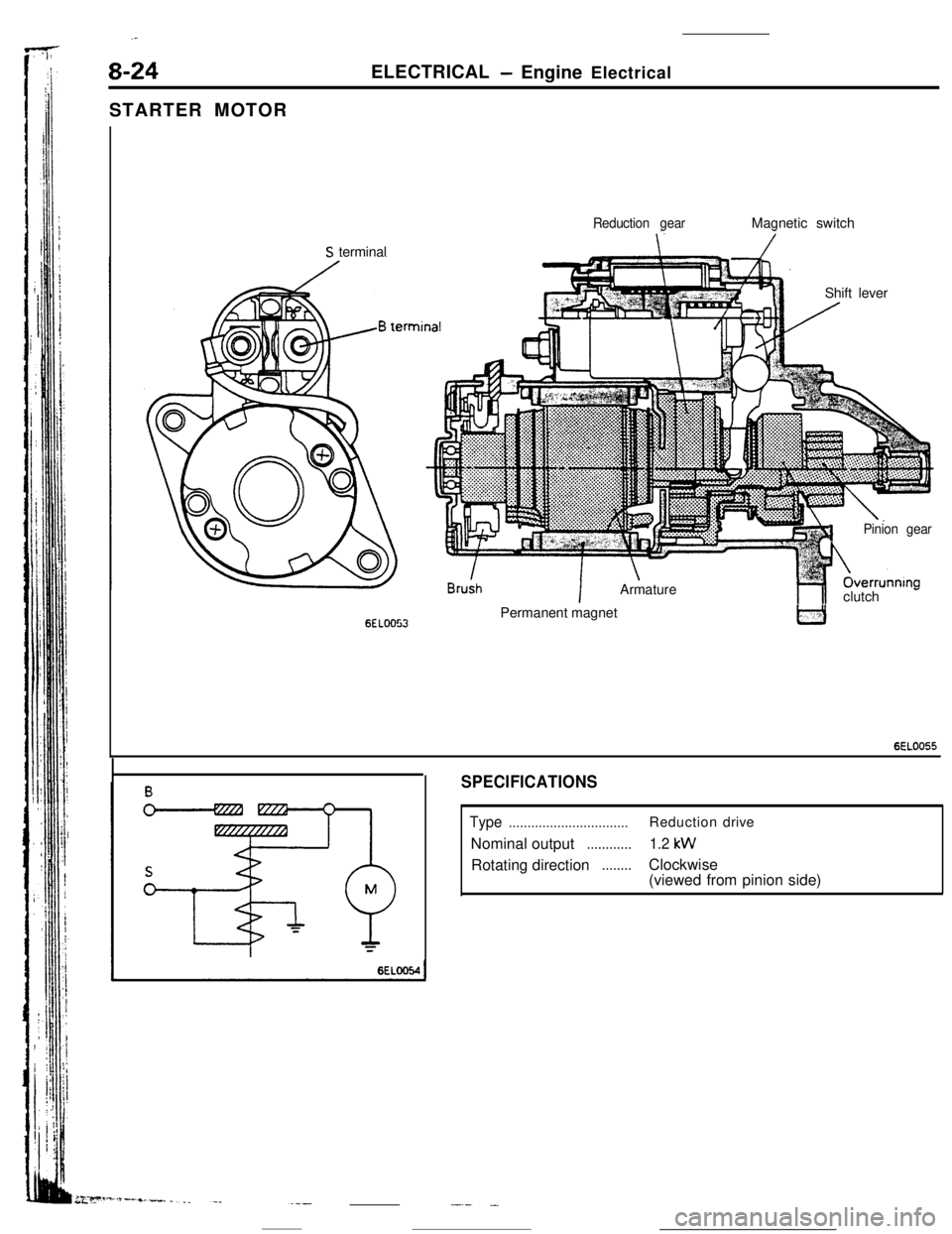
8-24ELECTRICAL- Engine Electrical
STARTER MOTOR
Reduction gearMagnetic switch
S terminal
Shift lever
6ELOO53
!n
IArmature
1Pinion gearOverrunnIng
hlclutch -Permanent magnet
6EL0055
SPECIFICATIONS
Type................................Reductiondrive
Nominal output
............1.2 kWRotating direction
........Clockwise
(viewed from pinion side)
-.- .-


