oil viscosity MITSUBISHI ECLIPSE 1990 Service Manual
[x] Cancel search | Manufacturer: MITSUBISHI, Model Year: 1990, Model line: ECLIPSE, Model: MITSUBISHI ECLIPSE 1990Pages: 391, PDF Size: 15.27 MB
Page 237 of 391

MANUAL TRANSAXLE <4WD> - Viscous Coupling .(VClJ)21-13In contrast, the inner plates have no such spacer rings, and
each can slide to some extent over the hub spline shaft
between the outer plates.
The space between the housing and outer and inner plates is
filled with mixture of silicone oil and air.
Plate A
Moving atvelocity V*
OPERATION OF THE VISCOUS COUPLINGPrinciples of operation
The viscous coupling is a kind of fluid clutch that uses viscous
resistance (shear stress) of the fluid to transmit power or limit
differential action.
For this purpose, the viscous coupling uses silicone oil whose
viscosity is less variable with temperature changes.
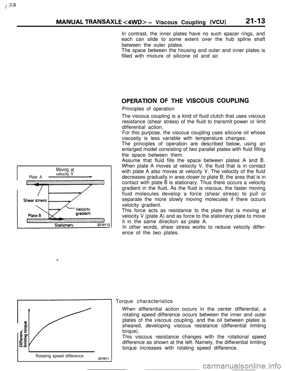
The principles of operation are described below, using an
enlarged model consisting of two parallel plates with fluid filling
the space between them.
Assume that fluid fills the space between plates A and
B.When plate A moves at velocity V, the fluid that is in contact
with plate A also moves at velocity V. The velocity of the fluid
decreases gradually in area closer to plate B; the area that is in
contact with plate
B is stationary. Thus there occurs a velocity
gradient in the fluid. As the fluid is viscous, the faster moving
fluid molecules develop a force (shear stress) to pull or
separate the more slowly moving molecules if there occurs
velocity gradient.
This force acts as resistance to the plate that is moving at
velocity
V (plate A) and as force to the stationary plate to move
it in the same direction as plate A.
In other words, shear stress works to reduce velocity differ-
ence of the two plates.
1 Torque characteristics
Rotating speed differenceWhen differential action occurs in the center differential, a
rotating speed difference occurs between the inner and outer
plates of the viscous coupling, and the oil between plates is
sheared, developing viscous resistance (differential limiting
torque).This viscous resistance changes with the rotational speed
difference as shown at the left. Namely, the differential limiting
torque increases with rotating speed difference.
Page 269 of 391

‘4) Once the operation is step (2) is completed, the
hydraulic control device functions by hydraulic
pressure force to change the state of the
clutches and brakes to accomplish the gear
shifting. To minimize the shock that would
otherwise be produced during gear shifting,
hydraulic pressure is controlled during the gear
shifting period by the “duty control” of the
pressure control solenoid valve. The duty control
is explained later.
‘HYDRAULIC PRESSURE CONTROL DURING
SHFIING(1) The hydraulic pressure that functions during
gear shifting to engage the clutches and apply
the brakes is regulated by the pressure control
valve, The hydraulic pressure that works on the
pressure control valve is further regulated by the
pressure control solenoid valve which functions
under the control of the transaxle control unit.
The transaxle control unit controls the solenoid
valve through the duty control, thus providing
appropriate regulation of the hydraulic pressure.
(2)
(3)
(4)The transaxle control unit decides the timing of
the gear shifting period (during which ‘it per-
forms hydraulic pressure control for gear shift-
ing) according to the change in the kickdown
drum rotating speed that it detects. The unit
identifies the time just before the kickdown
brake is applied and uses that as the timing for
initiating control of the hydraulic pressure which
is to be applied to the kickdown brake.
When the transaxle is cold, the fluid viscosity is
high, causing slower oil pressure response. in
such conditions, the transaxle control unit pro-
vides a correction for the oil pressure by
changing the control duty of the pressure control
solenoid valve.
This control is performed when the fluid temper-
atures as indicated by the oil temperature
sensor is lower than
60°C (140°F).After the engine has been started and the
vehicle is inmotion, the transaxle
continues torefine its performance
est possiblegear shifting.control unit
for smooth-
tHFigure B
- Duty(%)
17500661750067
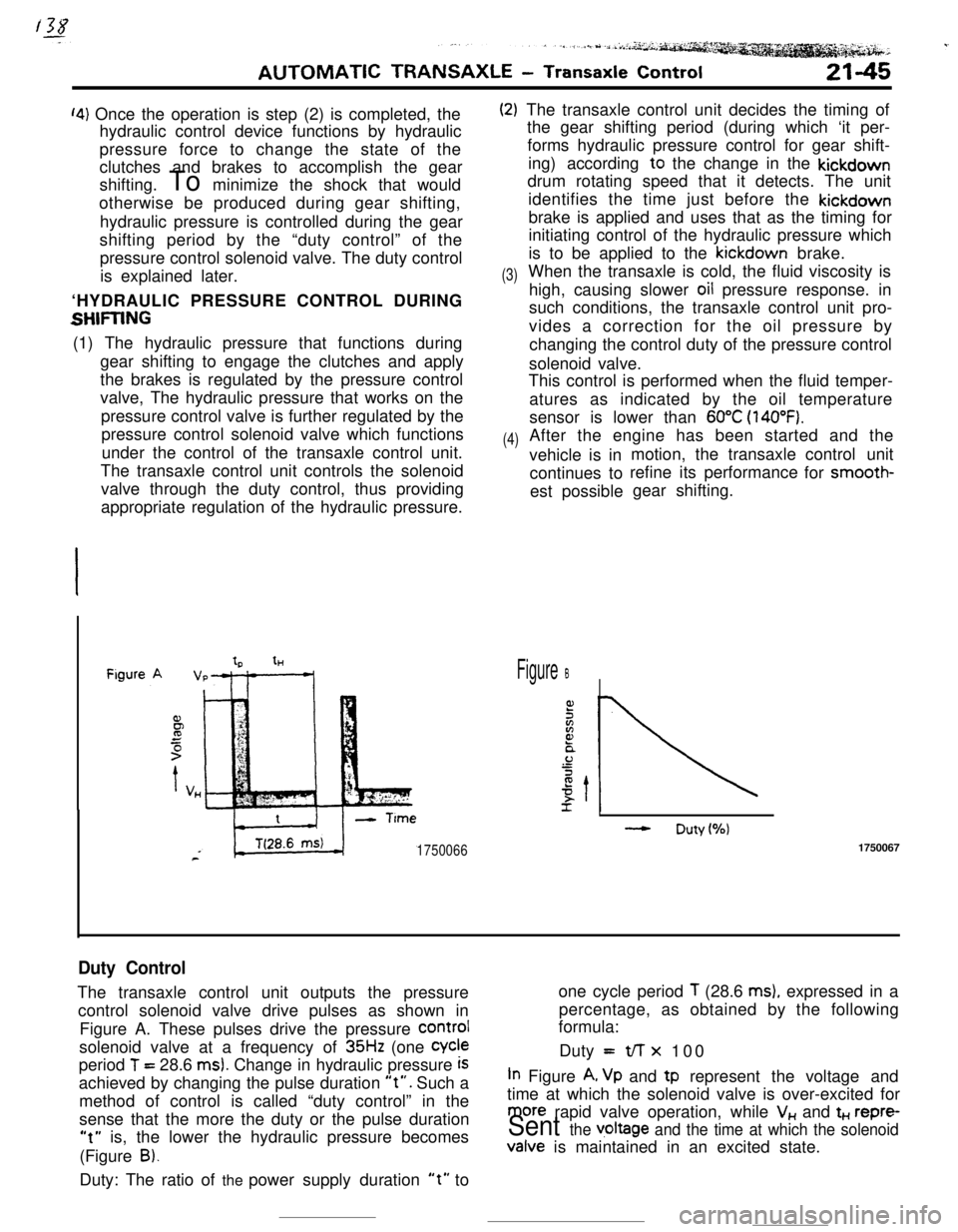
Duty ControlThe transaxle control unit outputs the pressureone cycle period
T (28.6 ms), expressed in a
control solenoid valve drive pulses as shown inpercentage, as obtained by the following
formula:
Figure A. These pulses drive the pressure
COrmIsolenoid valve at a frequency of
35Hz (one Cycleperiod
T = 28.6 ms). Change in hydraulic pressure iSDuty =t/-r x 100
achieved by changing the pulse duration
“t”. Such aIn Figure A, Vp and tp represent the voltage and
method of control is called “duty control” in thetime at which the solenoid valve is over-excited for
sense that the more the duty or the pulse duration
more rapid valve operation, while V,, and t+., repre-
“t” is, the lower the hydraulic pressure becomesSent the v,oltage and the time at which the solenoid(Figure
B).Valve is maintained in an excited state.
Duty: The ratio of the power supply duration
“t” to