clock MITSUBISHI ECLIPSE 1990 Service Manual
[x] Cancel search | Manufacturer: MITSUBISHI, Model Year: 1990, Model line: ECLIPSE, Model: MITSUBISHI ECLIPSE 1990Pages: 391, PDF Size: 15.27 MB
Page 69 of 391
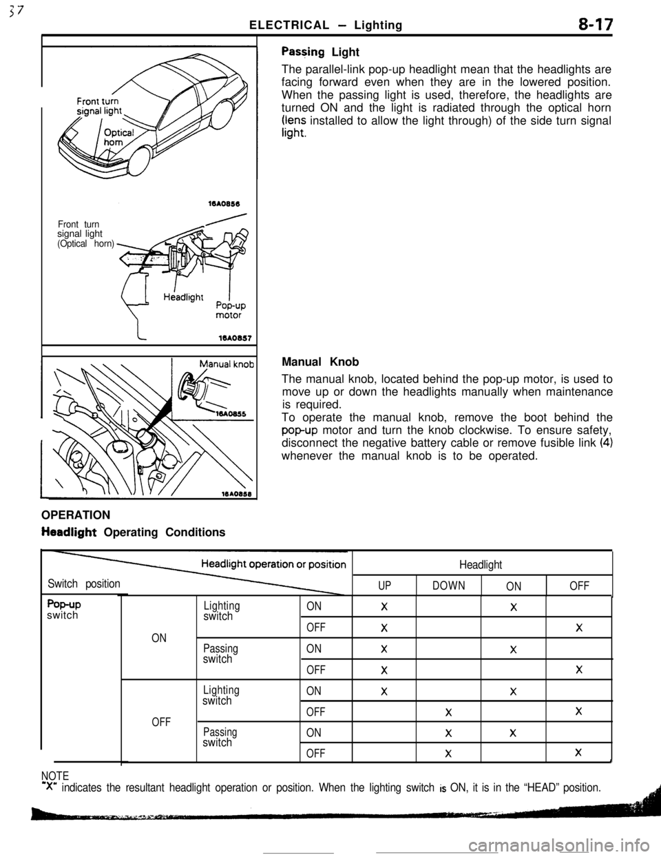
ELECTRICAL - Lighting8-17
Front turnsignal light
(Optical horn)
Pas+ing Light
The parallel-link pop-up headlight mean that the headlights are
facing forward even when they are in the lowered position.
When the passing light is used, therefore, the headlights are
turned ON and the light is radiated through the optical horn
rr,“;; installed to allow the light through) of the side turn signal
OPERATION
tieadlight Operating ConditionsManual Knob
The manual knob, located behind the pop-up motor, is used to
move up or down the headlights manually when maintenance
is required.
To operate the manual knob, remove the boot behind the
popup motor and turn the knob clockwise. To ensure safety,
disconnect the negative battery cable or remove fusible link
(4)whenever the manual knob is to be operated.
Switch positionUP
Headlight
DOWN
ONOFF
f%+Pswitch
ON
OFF
Lightingswitch
Passingswitch
Lightingswitch
Passingswitch
ONXX
OFF
XX
ONXX
OFF
XX
ONXX
OFFXX
ONXX
OFF
XXI
NOTE
‘X” indicates the resultant headlight operation or position. When the lighting switch is ON, it is in the “HEAD” position.
Page 75 of 391
ELECTRICAL- Ermine Electrical8-23
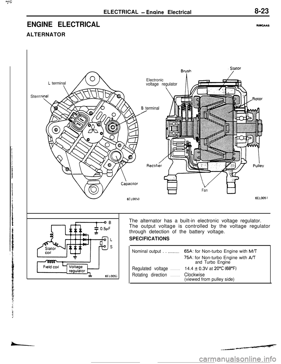
ENGINE ELECTRICALRoaGAABALTERNATOR
L terminal\Stern
Electronicvoltage regulator
B terminal/
Rectlfber‘i ‘IT
VFantl
GEL0051The alternator has a built-in electronic voltage regulator.
The output voltage is controlled by the voltage regulator
through detection of the battery voltage.
SPECIFICATIONS
Nominal output . . .._...._..65A: for Non-turbo Engine with M/T
75A: for Non-turbo Engine with AAand Turbo Engine
Regulated voltage. . . . . . . .14.4 f 0.3V at 20°C (68°F)
Rotating direction. . . . . . . .Clockwise(viewed from pulley side)
-
Page 76 of 391
.-
8-24ELECTRICAL- Engine Electrical
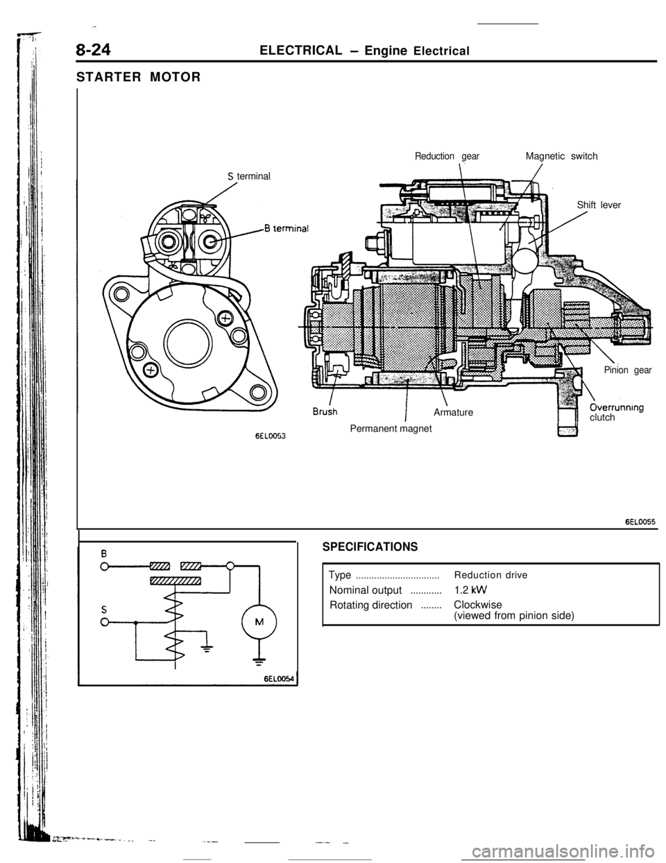
STARTER MOTOR
Reduction gearMagnetic switch
S terminal
Shift lever
6ELOO53
!n
IArmature
1Pinion gearOverrunnIng
hlclutch -Permanent magnet
6EL0055
SPECIFICATIONS
Type................................Reductiondrive
Nominal output
............1.2 kWRotating direction
........Clockwise
(viewed from pinion side)
-.- .-
Page 128 of 391
14-16FUEL SYSTEM - Sensors
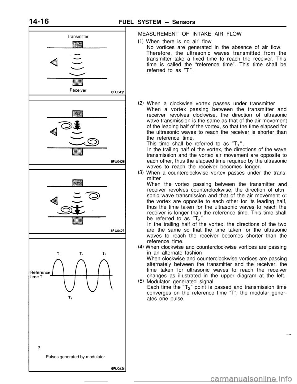
TransmitterMEASUREMENT OF INTAKE AIR FLOW
(1) When there is no air’ flow
No vortices are generated in the absence of air flow.
Therefore, the ultrasonic waves transmitted from the
transmitter take a fixed time to reach the receiver. This
time is called the “reference time”. This time shall be
referred to as
“T”.
Recetver6FUo42!
6FUO426
6f UO42;
TIT1Tl
~tee;ence
9%
T22
Pulses generated by modulator
(2) When a clockwise vortex passes under transmitter
When a vortex passing between the transmitter and
receiver revolves clockwise, the direction of ultrasonic
wave transmission is the same as that of the air movement
of the leading half of the vortex, so that the time elapsed for
the ultrasonic waves to reach the receiver is shorter than
the reference time.
This time shall be referred to as
“T, “.
In the trailing half of the vortex, the directions of the wave
transmission and the vortex air movement are opposite to
each other, thus the elapsed time required by the ultrasonic
waves to reach the receiver becomes longer.
(3) When a counterclockwise vortex passes under the trans-
mitter
When the vortex passing between the transmitter
and-.receiver revolves counterclockwise, the direction of ultr:
sonic wave transmission and that of the air movement
OTthe vortex are opposite to each other for its leading half,
thus the time taken for the ultrasonic waves to reach the
receiver is longer than the reference time. This time shall
be referred to as
“Tz”.In the trailing half of the vortex, the directions of the two
are the same so that the time taken for the ultrasonic
waves to reach the receiver becomes shorter than the
reference time.
(4) When clockwise and counterclockwise vortices are passing
in an alternate fashion
When clockwise and counterclockwise vortices are passing
alternately between the transmitter and the receiver, the
time taken for ultrasonic waves to reach the receiver
changes as illustrated in the upper diagram at the left.
(5) Modulator generated signal
Each time the “T2” point is passed and transmission time
converges on the reference time “T”, the modular gener-
ates one pulse.
-
Page 160 of 391
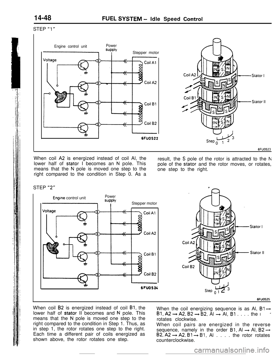
14-48STEP
“1”
FUEL SYSTEM - Idle Speed Control
Engine control unitPowerSUPPlYI IStepper motor
Stator I
Stator II
I6FUO522When coil
A2 is energized instead of coil Al, the
lower half of stator I becomes an
N pole. This
means that the
N pole is moved one step to the
right compared to the condition in Step 0. As aresult, the
S pole of the rotor is attracted to the Npole of the stator and the rotor moves, or rotates,
one step to the right.
STEP
“2”
Engine control unitPower
=JPPb
1 IStepper motor
Stator IStator II
mI6FU0524w3Step o 1 2
6FUO525When coil
B2 is energized instead of coil Bl, the
lower half of stator II becomes and
N pole. This
means that the
N pole is moved one step to the
right compared to the condition in Step 1. Thus, as
in step 1, the rotor rotates one step to the right.
Each time a different pair of coils energized as
shown above, the rotor rotates one step.When the coil energizing sequence is as Al, B!
3
Bl, A2 -) A2. B2 + B2. Al + Al, Bl . . . . the I*rotates clockwise.
When coil pairs are energized in the reverse
sequence, namely in the order
Bl, Al + Al, B2 -)
B2, A2 --) A2, Bl 3 Bl, Al . . . . the rotor rotates
counterclockwise.
Page 245 of 391
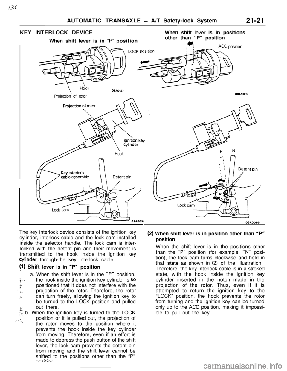
AUTOMATIC TRANSAXLE - A/T Safety-lock System21-21KEY INTERLOCK DEVICEWhen shift lever is in positions
When shift lever is in “P” position
LOCK
\Hcjok
Projection of rotorother than “P” position
KC position
Hook
\ \Detent pin
Lock &mThe key interlock device consists of the ignition key
cylinder, interlock cable and the lock cam installed
inside the selector handle. The lock cam is inter-
locked with the detent pin and their movement is
‘transmitted to the hook inside the ignition key
Q4inder through-the key interlock cable.
!l) Shift lever is in “P” position
a. When the shift lever is in the
“P” position.
j..the hook inside the ignition key cylinder is SO
i-.3positioned that it does not interfere with the’ .L.,projection of the rotor. Therefore, the rotor
:‘-can turn freely, allowing the ignition key to
be turned to the LOCK position and pulled
out there.
is, b. When the ignition key is turned to the LOCK
i,- c.position or it is pulled out, the projection of‘..the rotor moves to the position where it
prevents the hook inside the key cylinder
from moving. Therefore, even if an effort is
made to depress the push button of the shift
lever, the lock cam prevents the detent pin
from moving and the shift lever cannot be
shifted to the positions other than the “P”nnrit;nn
09*0090
(2) When shift lever is in position other than “P”position
When the shift lever is in the positions other
than the
“P” position (for example. “N” posi-
tion), the lock cam turns clockwise and held in
that
.state as shown in (2) of the illustration.
Therefore, the key interlock cable is in a stroked
state, with the hook inside the ignition key
cylinder inserted in the notch made in the
projection of the rotor. Thus, even if it is
attempted to return the ignition key to the
“LOCK” position, the hook prevents the rotor
from turning and the ignition key can be turned
only up to the
ACC position, making it impossi-
ble to pull out the key.
Page 255 of 391
iAUTOMATIC TRANSAXLE
- Transaxle Mechanism
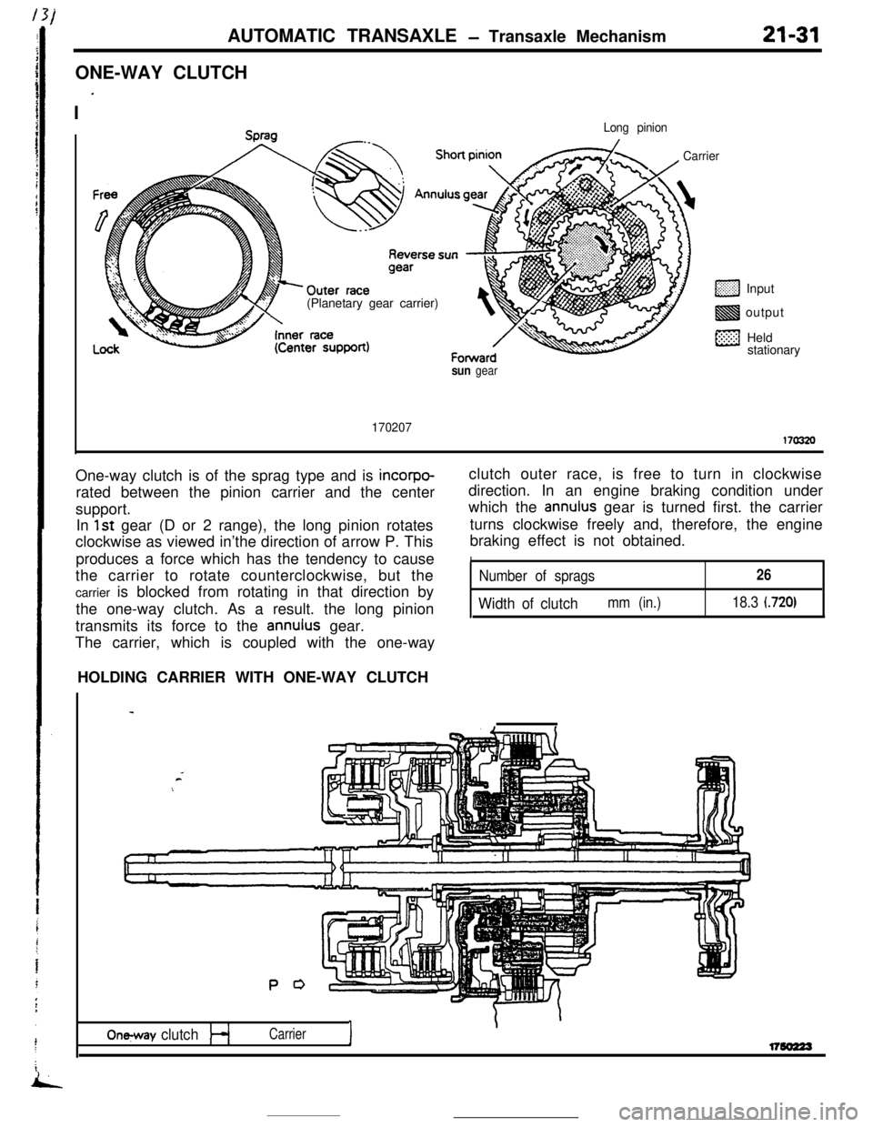
ONE-WAY CLUTCH
I
’
21-31
Long pinion(Planetary gear carrier)
CarrierInput
output
Held
stationary
sun gear
170207170320One-way clutch is of the sprag type and is
incorpo-rated between the pinion carrier and the center
support.
In
1st gear (D or 2 range), the long pinion rotates
clockwise as viewed in’the direction of arrow P. This
produces a force which has the tendency to cause
the carrier to rotate counterclockwise, but the
carrier is blocked from rotating in that direction by
the one-way clutch. As a result. the long pinion
transmits its force to the
annulus gear.
The carrier, which is coupled with the one-wayclutch outer race, is free to turn in clockwise
direction. In an engine braking condition under
which the
annulus gear is turned first. the carrier
turns clockwise freely and, therefore, the engine
braking effect is not obtained.
INumber of sprags26
Width of clutchmm (in.)18.3 (720)HOLDING CARRIER WITH ONE-WAY CLUTCH
P 0
On-y clutchI
\Carrierl7so223
Page 257 of 391
AUTOMATIC TRANSAXLE - Transaxle Mechanism21-33
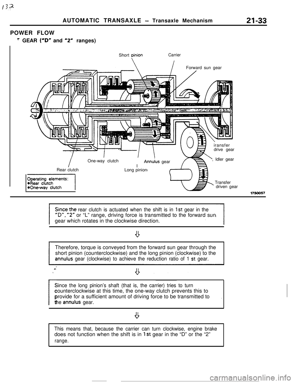
POWER FLOW
T GEAR (“D” and ‘2” ranges)
Short
DinionCarrier
IForward sun gear
IOne-way clutch
IAnn&s gear
Rear clutch
-1Long pinioniransfer
drive gear
, Idler gear
Transfer* driven gear
17!50057
rear clutch is actuated when the shift is in 1 st gear in the
“D”. “2” or “L” range, driving force is transmitted to the forward sun
gear which rotates in the clockwise direction.
ITherefore, torque is conveyed from the forward sun gear through the
short pinion (counterclockwise) and the long pinion (clockwise) to theannulus gear (clockwise) to achieve the reduction ratio of 1 st gear.
Since the long pinion’s shaft (that is, the carrier) tries to turn
/counterclockwise at this time, the one-way clutch prevents this to
provide for a sufficient amount of driving force to be transmitted to
.
the annulus gear.
,
This means that, because the carrier can turn clockwise, engine brakedoes not function when the shift is in
1 st gear in the “D” or the “2”
range.
Page 259 of 391
2ND’ GEARAUTOMATIC
TRANSAXLE - Transaxle Mechanism21-35
Kickdown brake
I
Shon pinion
\Forward sun gear
1.//LT.//. , ,’ .‘,,i.:,;:.:‘.,.‘,\/
/
Annulus gearLong pinion
Rear clutch/Reverse sun gear
fharatinn damants:
-, IWI WUIUI IWickdown brakeI
.
c
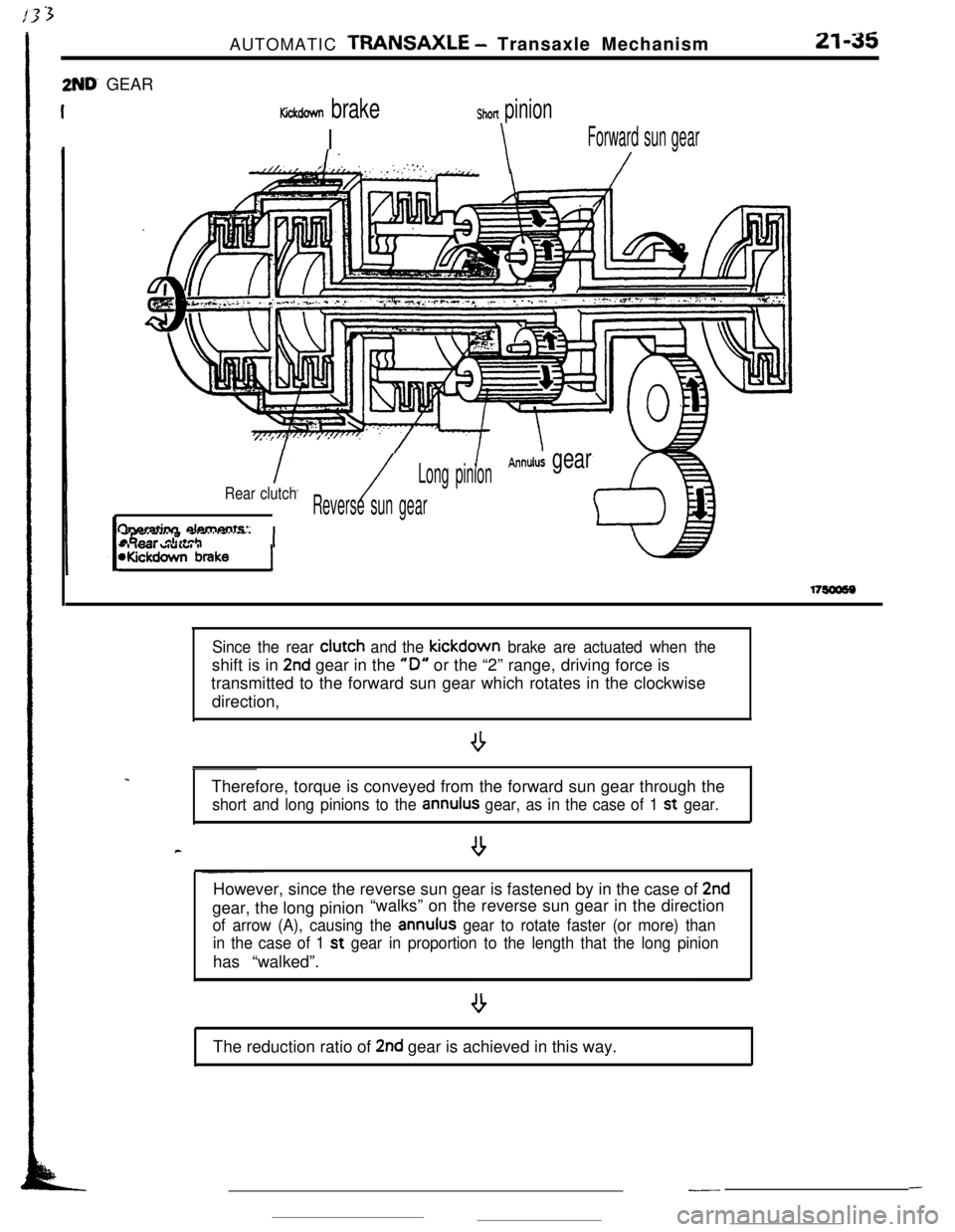
Since the rear clutch and the kickdown brake are actuated when theshift is in
2nd gear in the “0” or the “2” range, driving force is
transmitted to the forward sun gear which rotates in the clockwise
direction,
Therefore, torque is conveyed from the forward sun gear through the
short and long pinions to the annulus gear, as in the case of 1 st gear.
--However, since the reverse sun gear is fastened by in the case of
2ndgear, the long pinion“walks” on the reverse sun gear in the direction
of arrow (A), causing the annulus gear to rotate faster (or more) than
in the case of 1 st
gear in proportion to the length that the long pinionhas “walked”.
The reduction ratio of
2nd gear is achieved in this way.
---
Page 262 of 391
21-38RNERSEAUTOMATIC TRANSAXLE - Transaxle Mechanism
Low/Reverse brakeLong pinion
\I
IFront clutchIReverse sun gearIAnnulus
l
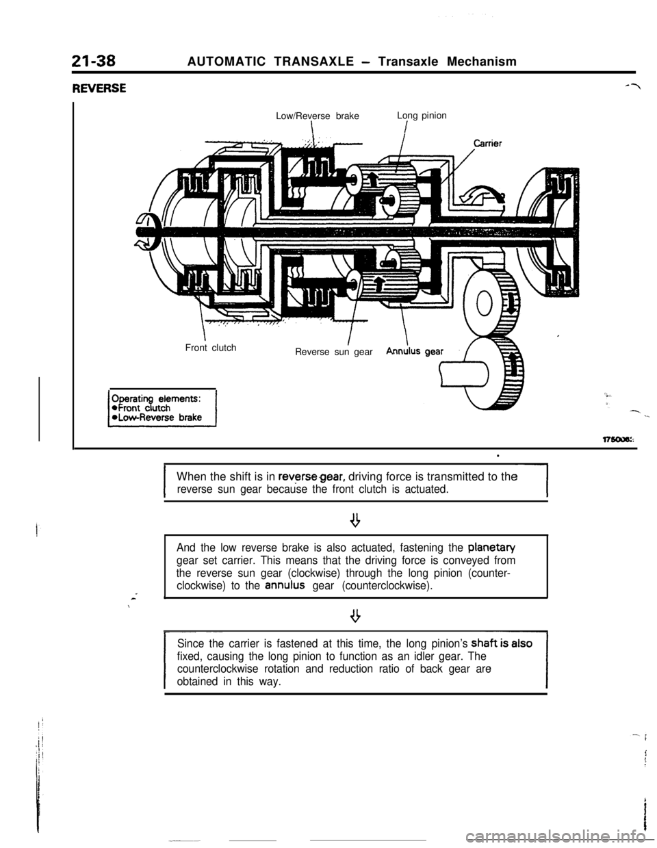
IWhen the shift is in
reverse.gear, driving force is transmitted to the
reverse sun gear because the front clutch is actuated.-1
And the low reverse brake is also actuated, fastening the planetan/
gear set carrier. This means that the driving force is conveyed from
the reverse sun gear (clockwise) through the long pinion (counter-
clockwise) to the
annulus gear (counterclockwise).*
/
- ~~_~
Since the carrier is fastened at this time, the long pinion’s
fixed, causing the long pinion to function as an idler gear. The
counterclockwise rotation and reduction ratio of back gear are
obtained in this way.