compression ratio MITSUBISHI ECLIPSE 1990 Service Manual
[x] Cancel search | Manufacturer: MITSUBISHI, Model Year: 1990, Model line: ECLIPSE, Model: MITSUBISHI ECLIPSE 1990Pages: 391, PDF Size: 15.27 MB
Page 18 of 391

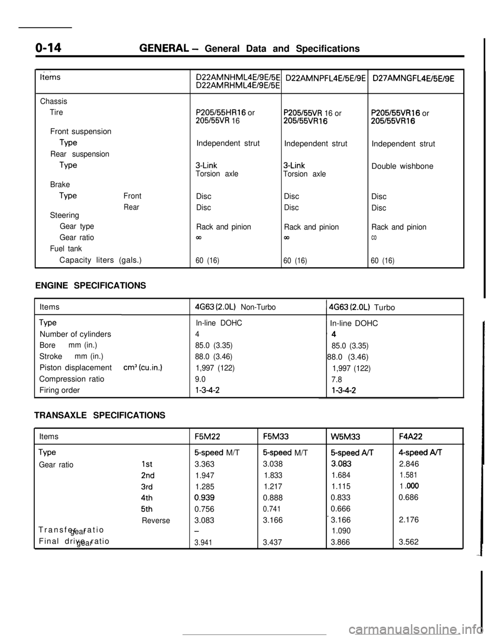
o-14GENERAL - General Data and Specifications
tiems
Chassis
TireFront suspension
Type
Rear suspensionType
Brake
TypeFront
RearSteering
Gear type
Gear ratio
Fuel tankCapacity liters (gals.)
P205/55HR16 or
205l55VR 16Independent strut
3-Link
Torsion axleDisc
Disc
Rack and pinion
m
60 (16)
P205/55VR 16 or205155VR16Independent strut
3-Link
Torsion axleDisc
Disc
Rack and pinion
00
60 (16)
P205155VR16 or205155VR16Independent strut
Double wishbone
Disc
Disc
Rack and pinion
co
60 (16)ENGINE SPECIFICATIONS
Items
TypeNumber of cylinders
Boremm (in.)Stroke
mm (in.)Piston displacement
Compression ratio
Firing order
cm3 (cu.in.)
4G63 (2.OL) Non-Turbo1 4663 (2.OL) Turbo
In-line DOHC~ In-line DOHC
4‘4
85.0 (3.35)
85.0 (3.35)
88.0 (3.46)88.0 (3.46)
1,997 (122)
1,997 (122)
9.0
7.8l-3-4-2l-3-4-2
TRANSAXLE SPECIFICATIONS
Items
Type
Gear ratioTransfer ratio
gearFinal drive ratio
gear
1st
2nd
3rd4th5th
ReverseF5M22F5M33
W5M33F4A22
5-speed M/T5-speed M/T&speed ArF4-speed AiT
3.3633.038
3.0832.846
1.9471.8331.6841.581
1.2851.2171.1151 .ooo0.9390.8880.8330.686
0.756
0.7410.666
3.0833.166
’3.1662.176
-1.090
3.9413.4373.8663.562
Page 87 of 391

=--Y
jl
1 /
i "
_. ---“._ _ _ ._ ..-..+_LI_y_--- -
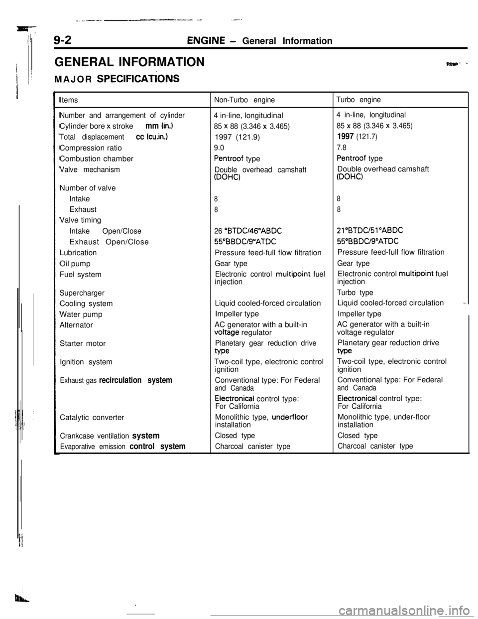
9-2ENGINE- General Information
GENERAL INFORMATION
MAJOR
SPEClFlCATiONS
Row- -
Items
Number and arrangement of cylinderCylinder bore x stroke
mm (in.)
Total displacementcc (cu.in.1Compression ratio
Combustion chamber
Valve mechanismNumber of valve
Intake
Exhaust
Valve timing
IntakeOpen/CloseExhaust Open/Close
Lubrication
Oil pump
Fuel system
SuperchargerCooling system
Water pump
Alternator
Starter motor
Ignition system
Exhaust gas recirculation systemCatalytic converter
Crankcase ventilation system
Evaporative emission control system
Non-Turbo engineTurbo engine4 in-line, longitudinal
4 in-line, longitudinal
85 x
88 (3.346 x 3.465)85 x 88 (3.346 x 3.465)1997 (121.9)
1997 (121.7)
9.07.8
Pentroof typePentroof type
Double overhead camshaftDouble overhead camshaft
(DOHC)(DOHC)
88
88
26 “BTDU46”ABDC21”BTDC/Sl”ABDC56BBDUS”ATDC55”BBDUS”ATDC
Pressure feed-full flow filtrationPressure feed-full flow filtration
Gear typeGear type
Electronic control multipoint
fuelElectronic control multipoint fuel
injectioninjection
Turbo typeLiquid cooled-forced circulationLiquid cooled-forced circulation
-Impeller typeImpeller type
AC generator with a built-involtage regulatorAC generator with a built-in
voltage regulator
Planetary gear reduction drivePlanetary gear reduction drivetype
Two-coil type, electronic controlTwo-coil type, electronic control
ignitionignition
Conventional type: For FederalConventional type: For Federal
and Canadaand Canada
Electronical control type:Electronical control type:
For CaliforniaFor CaliforniaMonolithic type,
under-floorMonolithic type, under-floor
installationinstallation
Closed typeClosed type
Charcoal canister typeCharcoal canister type
I
Page 126 of 391

14-14
.._~- ---.FUEL SYSTEM
- Sensors
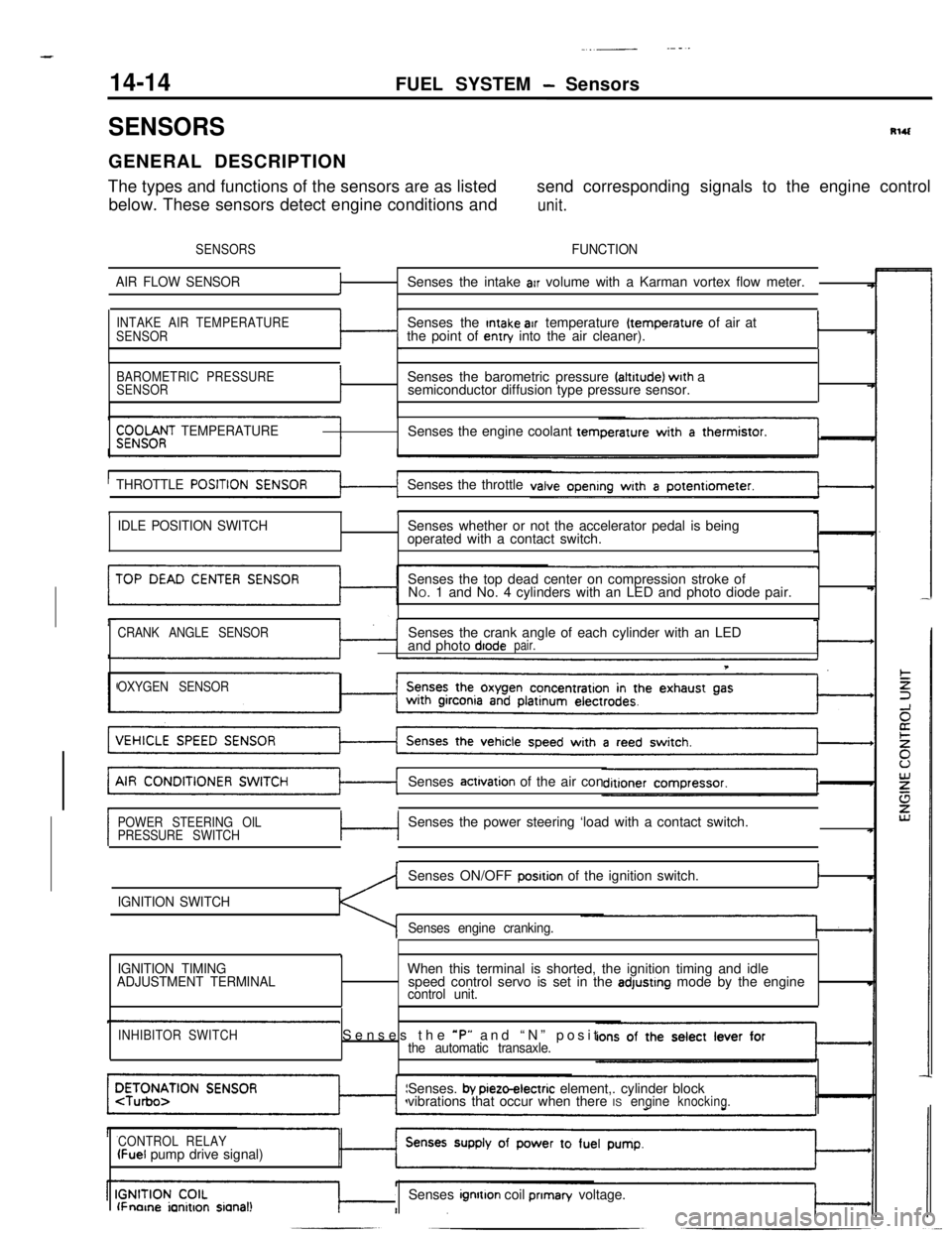
SENSORSRlUGENERAL DESCRIPTION
The types and functions of the sensors are as listedsend corresponding signals to the engine control
below. These sensors detect engine conditions and
unit.
SENSORSFUNCTION
AIR FLOW SENSOR
fSenses the intake arr volume with a Karman vortex flow meter.
INTAKE AIR TEMPERATURE
SENSORSenses the Intake air temperature (temperature of air at
the point of entry into the air cleaner).I
BAROMETRIC PRESSURE
SENSORISenses the barometric pressure faltrtude) wrth a
semiconductor diffusion type pressure sensor.
$;;OOf;T TEMPERATURESenses the engine coolant tern
THROTTLE
POSITISenses the throttle
tI
IDLE POSITION SWITCHSenses whether or not the accelerator pedal is being
operated with a contact switch.
Senses the top dead center on compression stroke of
NO. 1 and No. 4 cylinders with an LED and photo diode pair.
CRANK ANGLE SENSORSenses the crank angle of each cylinder with an LED
and photo diodepair.
T
OXYGEN SENSORSenses
actrvation of the air con
POWER STEERING OIL
PRESSURE SWITCHc-lSenses the power steering ‘load with a contact switch.
IGNITION SWITCHSenses ON/OFF
posrtion of the ignition switch.I
Senses engine cranking.
,
IGNITION TIMING
ADJUSTMENT TERMINALWhen this terminal is shorted, the ignition timing and idle
speed control servo is set in the adjustrng mode by the enginecontrol unit.
INHIBITOR SWITCHSenses the *P” and “N” positthe automatic transaxle.Senses.
by pieto-electric element,. cylinder block
vibrations that occur when there ISengineknocking.
CONTROL RELAY
(Fuel pump drive signal)
lFnorne ianitron sianal!Senses ignrtton coil prIman/ voltage.
Page 148 of 391

14-36FUEL SYSTEM- Fuel lniection Control
SFUOSlS
RESISTOR
co,.of the injector.
Because the injector must respond instantly to fuel-injection
signals, the number of windings of the coil is reduced in order
to facilitate current rise when the current is flowing in the coil.
By doing so, the resistance of the injector coil becomes smaller
and a greater amount of current can flow, with the result that
the calorific value of the injector coil becomes greater, and
1overheating occurs.
For this reason, for turbocharger-equipped models (which have
low resistance of the injector coil), a resistor is provided
between the power supply (+) and the injector in order to
regulate the amount of current flowing in the coil.
FUEL INJECTION TIMING (INJECTOR AC-
TIVATION TIMING)
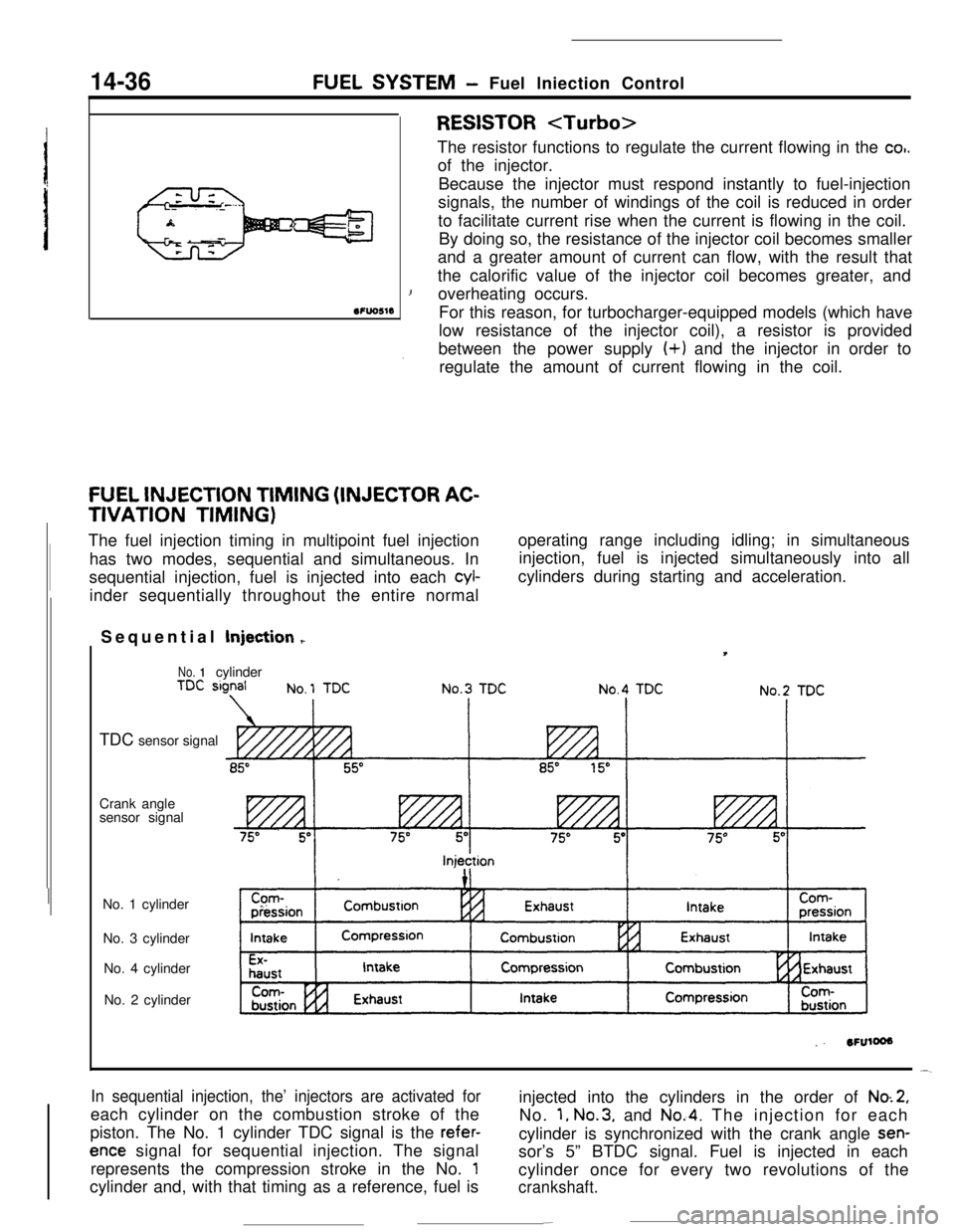
The fuel injection timing in multipoint fuel injection
has two modes, sequential and simultaneous. In
sequential injection, fuel is injected into each
cyl-inder sequentially throughout the entire normaloperating range including idling; in simultaneous
injection, fuel is injected simultaneously into all
cylinders during starting and acceleration.
Sequential Injection
r
No. 1cylinder
TDC sensor signal
Crank angle
sensor signal
No. 1 cylinder
No. 3 cylinder
No. 4 cylinder
No. 2 cylinder
In sequential injection, the’ injectors are activated foreach cylinder on the combustion stroke of the
piston. The No. 1 cylinder TDC signal is the
refer-
ence signal for sequential injection. The signal
represents the compression stroke in the No.
1cylinder and, with that timing as a reference, fuel isinjected into the cylinders in the order of
No.2,No.
1, No.3, and No.4. The injection for each
cylinder is synchronized with the crank angle
sen-sor’s 5” BTDC signal. Fuel is injected in each
cylinder once for every two revolutions of the
crankshaft.
-