coolant temperature MITSUBISHI ECLIPSE 1990 Service Manual
[x] Cancel search | Manufacturer: MITSUBISHI, Model Year: 1990, Model line: ECLIPSE, Model: MITSUBISHI ECLIPSE 1990Pages: 391, PDF Size: 15.27 MB
Page 59 of 391
ELECTRICAL -Relavs, Control Units and Sensors
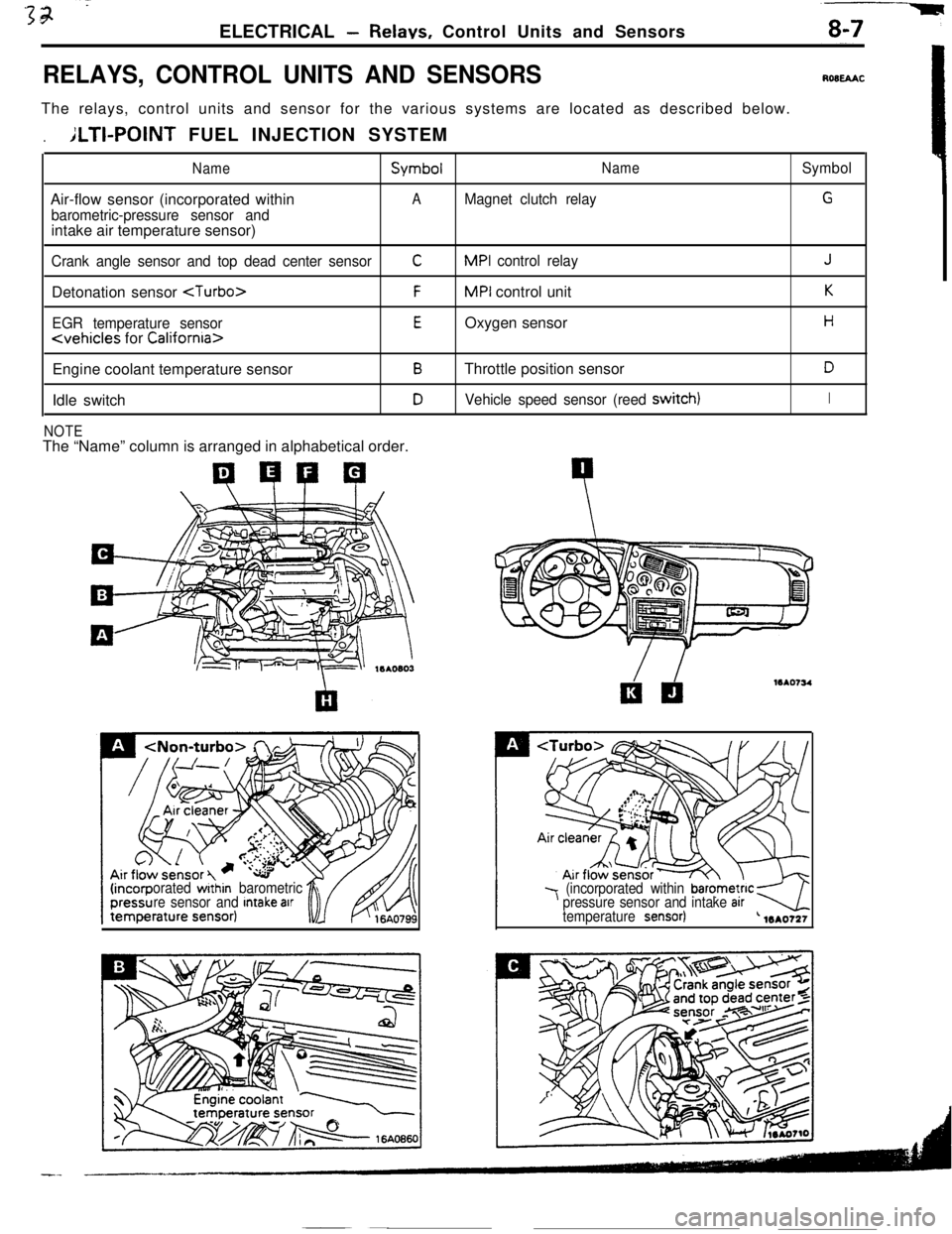
RELAYS, CONTROL UNITS AND SENSORSROBEAACThe relays, control units and sensor for the various systems are located as described below.
.ILTI-POINT FUEL INJECTION SYSTEM
NameSymbolNameSymbolAir-flow sensor (incorporated within
AMagnet clutch relayG
barometric-pressure sensor andintake air temperature sensor)
Crank angle sensor and top dead center sensorCMPI control relayJDetonation sensor
EGR temperature sensorEOxygen sensorH
Engine coolant temperature sensor
BThrottle position sensorDIdle switch
DVehicle speed sensor (reed switch)I
NOTEThe “Name” column is arranged in alphabetical order.
orated within barometric
re sensor and Intake arr7 (incorporated within barometnc kpressure sensor and intake arrtemperature sensor)-4L 1mo721
Page 63 of 391
1ELECTRICAL
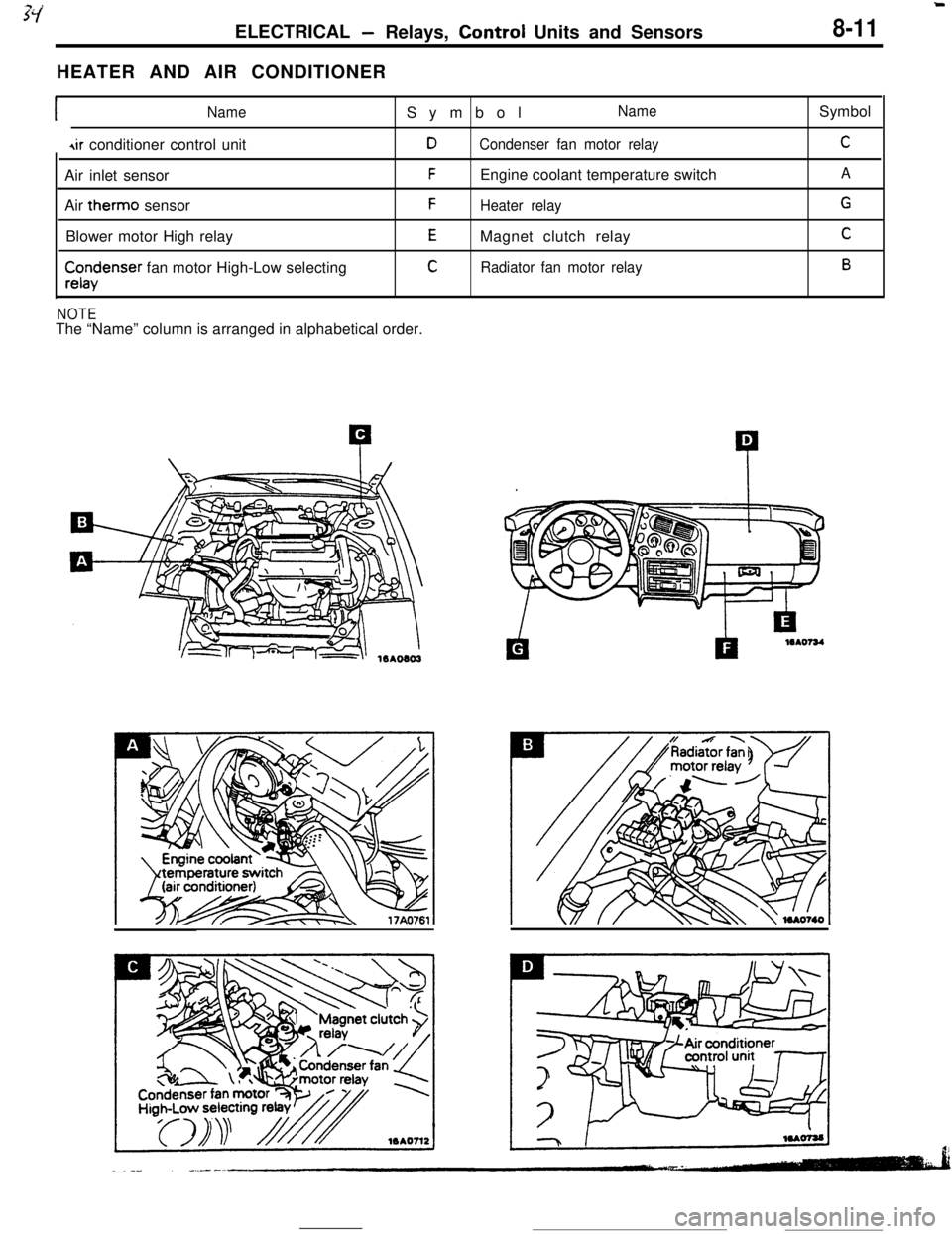
-Relays, Control Units and Sensors8-11HEATER AND AIR CONDITIONER
INameSymbolName
4ir conditioner control unitDCondenser fan motor relayAir inlet sensor
FEngine coolant temperature switch
Air therm0 sensor
FHeater relayBlower motor High relay
EMagnet clutch relay
$x$enser fan motor High-Low selectingCRadiator fan motor relay
NOTEThe “Name” column is arranged in alphabetical order.Symbol
C
A
G
C
B
Page 80 of 391
8-28ELECTRICAL- Engine Electrical
IGNITION TIMING CONTROL
Reading of Input signallgnitlon power
distribution control
(selection of power
transistor actlvatlon)Control mode
I II II IControl mode
dectsion data
Basic energlzatlon
I’
Engine control unitPower
Powertranststor “A”tranststor “B”
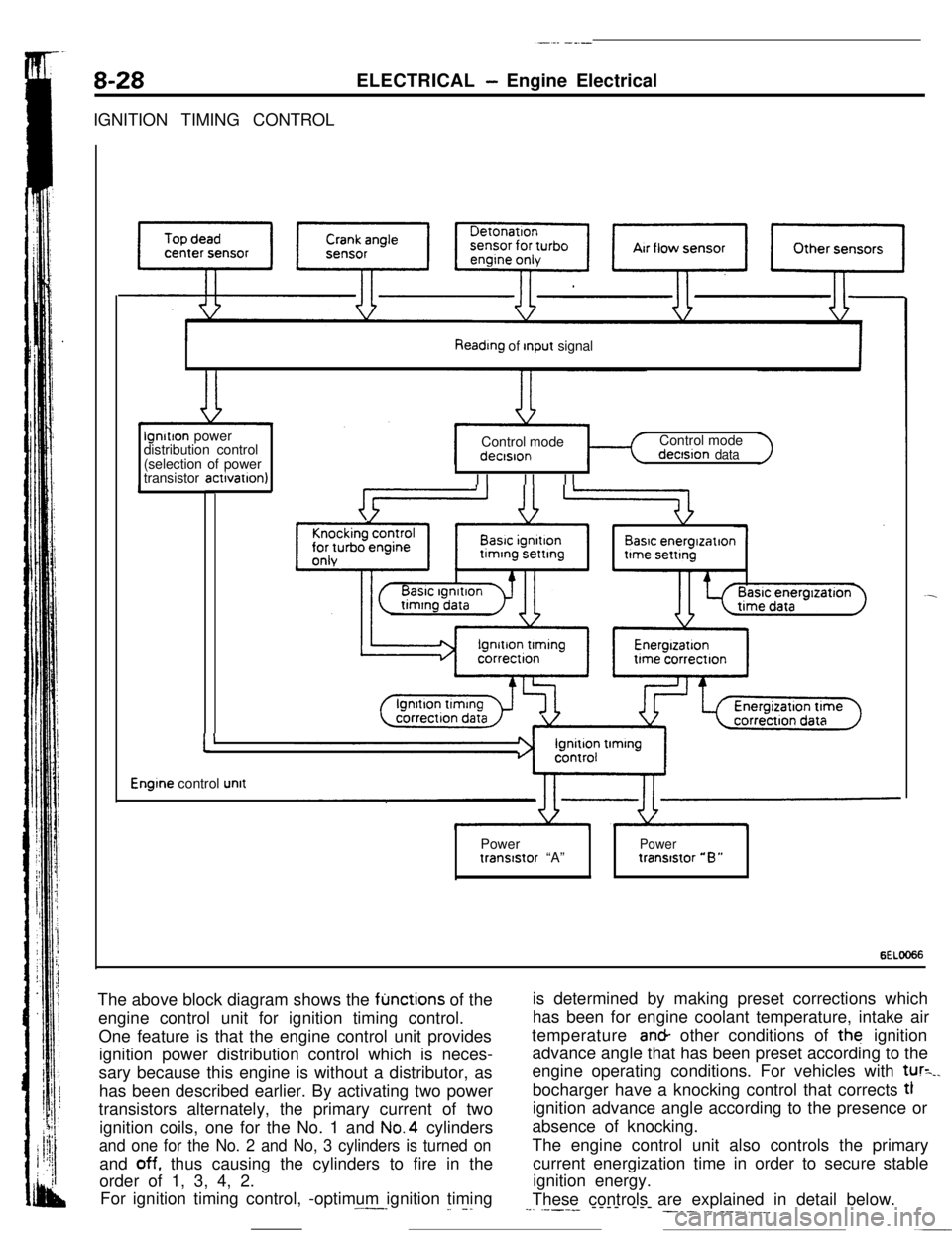
6ELOO66The above block diagram shows the
fljnctions of the
engine control unit for ignition timing control.
One feature is that the engine control unit provides
ignition power distribution control which is neces-
sary because this engine is without a distributor, as
has been described earlier. By activating two power
transistors alternately, the primary current of two
ignition coils, one for the No. 1 and No.4 cylinders
and one for the No. 2 and No, 3 cylinders is turned onand
off. thus causing the cylinders to fire in the
order of 1, 3, 4, 2.
For ignition timing control, -optimum ignition timing.^--_
_. -.is determined by making preset corrections which
has been for engine coolant temperature, intake air
temperature an& other conditions of the ignition
advance angle that has been preset according to the
engine operating conditions. For vehicles with
tur=_.bocharger have a knocking control that corrects tl
ignition advance angle according to the presence or
absence of knocking.
The engine control unit also controls the primary
current energization time in order to secure stable
ignition energy.
These controls are explained in detail below.
--. .----- ---- --- ___. .-. ___.,.__
Page 82 of 391
8-30ELECTRICAL - Engine Electrical
Ignition Advance Angle Control
While
cranking
Fixed angle(5”BTD.C)Engme coolantBarometnc‘-Intake air 1temperaturepressuretemperaturesensorsensor, sensor
Dunng normal operatlon4i+
Advance angle map valueEngine
coolantBarometricIntake airaccording to engine speed4and intake air volumetemperature- pressure__c temperature 4
correctioncorrectloncorrectton
Durtng ignition tlmmg adjustment
Fixed angle(5”BTDC)
c
=ower transistor
-$To ignition
coil
s
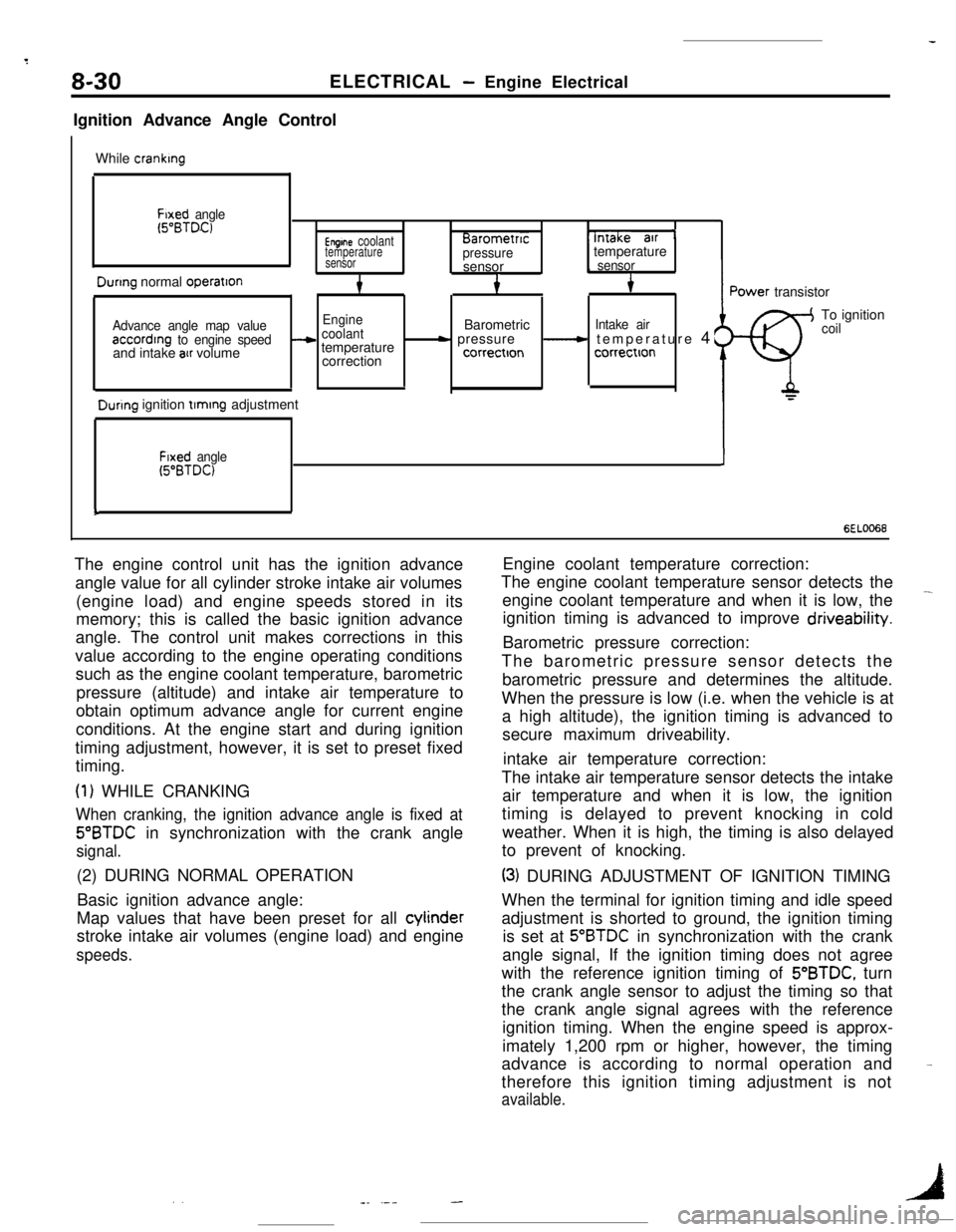
6EL0066The engine control unit has the ignition advance
angle value for all cylinder stroke intake air volumes
(engine load) and engine speeds stored in its
memory; this is called the basic ignition advance
angle. The control unit makes corrections in this
value according to the engine operating conditions
such as the engine coolant temperature, barometric
pressure (altitude) and intake air temperature to
obtain optimum advance angle for current engine
conditions. At the engine start and during ignition
timing adjustment, however, it is set to preset fixed
timing.
(1) WHILE CRANKING
When cranking, the ignition advance angle is fixed at
5”BTDC in synchronization with the crank angle
signal.(2) DURING NORMAL OPERATION
Basic ignition advance angle:
Map values that have been preset for all cylinder
stroke intake air volumes (engine load) and engine
speeds.Engine coolant temperature correction:
The engine coolant temperature sensor detects the
engine coolant temperature and when it is low, the
-ignition timing is advanced to improve driveability.
Barometric pressure correction:
The barometric pressure sensor detects the
barometric pressure and determines the altitude.
When the pressure is low (i.e. when the vehicle is at
a high altitude), the ignition timing is advanced to
secure maximum driveability.
intake air temperature correction:
The intake air temperature sensor detects the intake
air temperature and when it is low, the ignition
timing is delayed to prevent knocking in cold
weather. When it is high, the timing is also delayed
to prevent of knocking.
(3) DURING ADJUSTMENT OF IGNITION TIMING
When the terminal for ignition timing and idle speed
adjustment is shorted to ground, the ignition timing
is set at
5”BTDC in synchronization with the crank
angle signal, If the ignition timing does not agree
with the reference ignition timing of 5’BTDC, turn
the crank angle sensor to adjust the timing so that
the crank angle signal agrees with the reference
ignition timing. When the engine speed is approx-
imately 1,200 rpm or higher, however, the timing
advance is according to normal operation and
therefore this ignition timing adjustment is not
available.
-
. .1-_ .---
Page 113 of 391
---
14-1
FUEL
RWA---
ACCELERATOR COMPONENTS
.72
Auto-cruise Control Switch
:.............. 77
Self-diagnosis and Input-check Functions
injector................................................................34
PRESSURi
CONTROL ............................................................
31
Fuel Tank............................................................i
injector................................................................
Specifications
izi
INTAKE
il
Coolant Temperature Sensor
;iI
General Description
: .................... 24
ignition Timing Adjustment Terminal ............
CA/T>.................................... 26
i:
..........
.-.---__-...- -.---.
Page 115 of 391
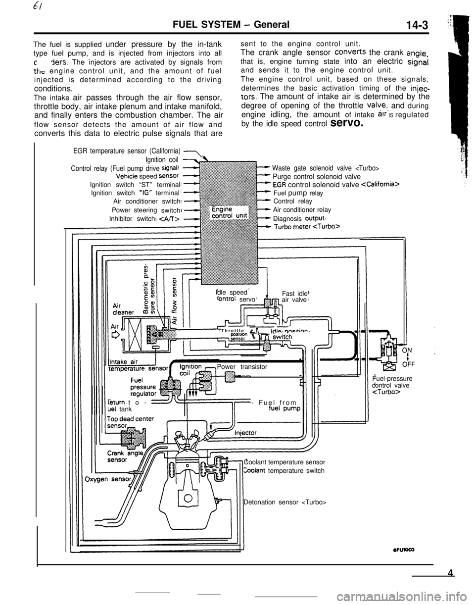
FUEL SYSTEM - General14-3The fuel is supplied under pressure by the in-tanksent to the engine control unit.
type fuel pump, and is injected from injectors into allThe crank angle sensor converts the crank
angle,
cders. The injectors are activated by signals fromthat is, engine turning state into an electric signal
tk, engine control unit, and the amount of fueland sends it to the engine control unit.
injected is determined according to the drivingThe engine control unit, based on these signals,
conditions.determines the basic activation timing of the
injec-The intake air passes through the air flow sensor,
tars. The amount of intake air is determined by the
throttle body, air intake plenum and intake manifold,degree of opening of the throttle
valye,, and during
and finally enters the combustion chamber. The airengine idling, the amount of intake
arr IS regulated
flow sensor detects the amount of air flow and
by the idle speed control servo.converts this data to electric pulse signals that are
EGR temperature sensor (California) 7
Waste gate solenoid valve
Purge control solenoid valve
EGR control solenoid valve
Control relay
Air conditioner relay
Diagnosis output
Ignition coil
Control relay (Fuel pump drive
signal)Vehicle speed
SensorIgnition switch “ST” terminal
Ignition switch
‘IG” terminal
Air conditioner switch
Power steering
switch
Inhibitor switch
Idle speed
ontrol servoFast idle
air valve
-Throttle
&r -kilo m-i&inn’Power transistorleturn to-
uel tank- Fuel from
Coolant temperature sensor
Coolant temperature switchFuel-pressure
control valve
4
Page 123 of 391
FUEL SYSTEM -Fuel Supply and Fuel Pressure Control
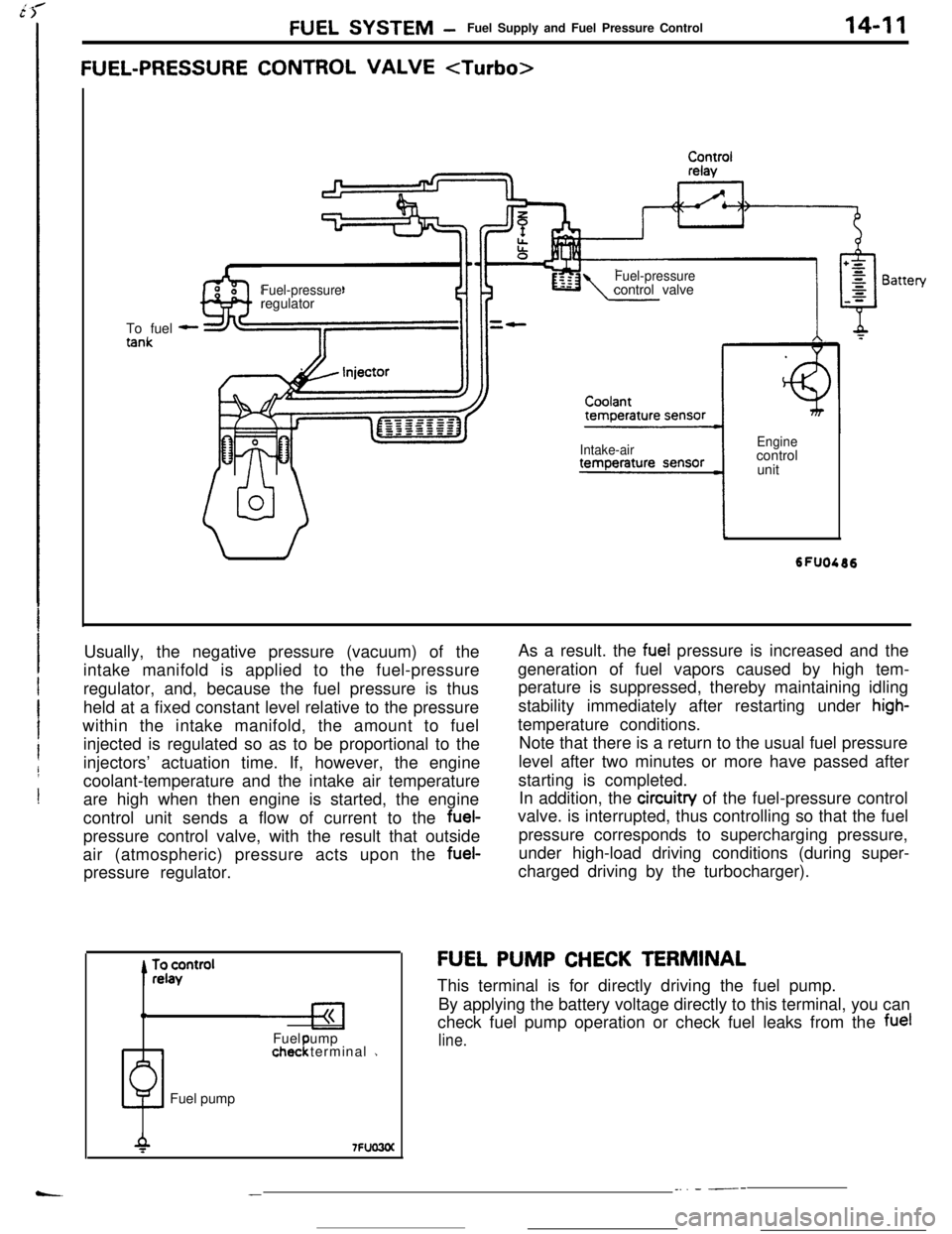
FUEL-PRESSURE CONTROL VALVE
14-11To fuel
-
Fuel-pressureregulatorFuel-pressurecontrol valve
Intake-airEnginecontrol
unit
Usually, the negative pressure (vacuum) of the
intake manifold is applied to the fuel-pressure
regulator, and, because the fuel pressure is thus
held at a fixed constant level relative to the pressure
within the intake manifold, the amount to fuel
injected is regulated so as to be proportional to the
injectors’ actuation time. If, however, the engine
coolant-temperature and the intake air temperature
are high when then engine is started, the engine
control unit sends a flow of current to the fuel-
pressure control valve, with the result that outside
air (atmospheric) pressure acts upon the fuel-
pressure regulator.
0Fuel ump
1chec terminal 1!Fuel pumpAs a result. the
fuel pressure is increased and the
generation of fuel vapors caused by high tem-
perature is suppressed, thereby maintaining idling
stability immediately after restarting under
high-temperature conditions.
Note that there is a return to the usual fuel pressure
level after two minutes or more have passed after
starting is completed.
In addition, the circuitry of the fuel-pressure control
valve. is interrupted, thus controlling so that the fuel
pressure corresponds to supercharging pressure,
under high-load driving conditions (during super-
charged driving by the turbocharger).
FU,EL PUMP CHECK TERMINAL
This terminal is for directly driving the fuel pump.
By applying the battery voltage directly to this terminal, you can
check fuel pump operation or check fuel leaks from the
fuel
line.
__. - ---
Page 124 of 391

140’I2FUEL SYSTEM- Intake Air Control
INTAKE AIR CONTROL
GENERAL DESCRIPTION
Rl4oA?, Speed adjusting screwIdle oositionswitch-
Throttle valve
0
+ Bypass air flow
before metenng
Q Bypass air fjow
Iafter metenng
Idle soeed control servo
-?hrottle position sensor
Fast idle air valve
oolant from thermostat case
ITo return pipe6FUO777Control of the volume of intake air is performed by the throttle
valve, the speed adjusting screw, the fast idle air valve and the
idle speed control servo, all of which are mounted on
ttithrottle body.
iControl by idle
w/d c;zk;;fast
hhidle air valve
Speed adjusting screwThrottle valve
m-30~22) of321 sofm 6of140~ 901164
Coolant temperature ‘C (OF)6Fuo!DURING ENGINE WARM UP
The intake air flow during fast idle is controlled by both the wax
actuated air valve which functions. in response to the engine
coolant temperature and the idle speed control servo that is
controlled by the engine control unit.
AFTER ENGINE HAS BEEN WARMED UP
Control of the intake air flow during curb idle (or the control of
curb idle speed) is performed by the idle speed control servo
which in turn is controlled by the engine control unit.
Refer to page 1445 for control of the idle speed control servo.The idle speed can be adjusted. by increasing or decreasing theintake air flow rate with the speed adjusting screw.
The off-idle intake air flow is controlled by the throttle
valve;operation of the accelerator pedal determines the degree that
the throttle valve is open at any particular moment.
-
.?‘h,
. .
Page 125 of 391
FUEL SYSTEM- Intake Air Control
SPECIFICATIONS
ternsThrottle body
Throttle bore diametermm
(in.1Fast idle air valve
TwValve closing temperature
“C (“F)
Idle speed control servo
TypeSpecifications
60 (2.362)
WAX type
Approximately 50
(122)Stepper motor type
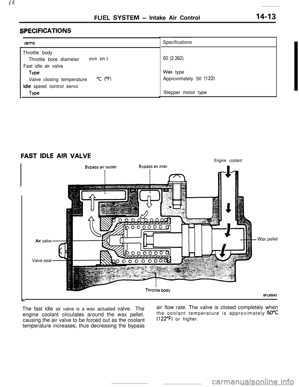
FAST IDLE AIR VALVEEngine coolant
LAir valve
Waxpellet
Valve seat
6FUO642The fast idle air valve is a wax actuated valve. The
engine coolant circulates around the wax pellet.
causing the air valve to be forced out as the coolant
temperature increases, thus decreasing the bypassair flow rate. The valve is closed completely when
the coolant temperature is approximately 50°C
(122°F) or higher.
Page 126 of 391
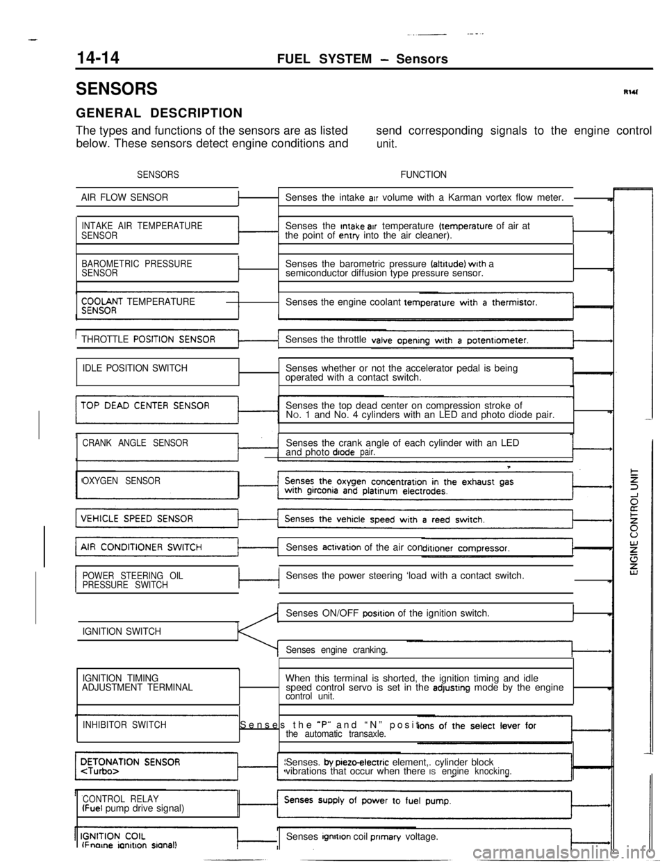
14-14
.._~- ---.FUEL SYSTEM
- Sensors
SENSORSRlUGENERAL DESCRIPTION
The types and functions of the sensors are as listedsend corresponding signals to the engine control
below. These sensors detect engine conditions and
unit.
SENSORSFUNCTION
AIR FLOW SENSOR
fSenses the intake arr volume with a Karman vortex flow meter.
INTAKE AIR TEMPERATURE
SENSORSenses the Intake air temperature (temperature of air at
the point of entry into the air cleaner).I
BAROMETRIC PRESSURE
SENSORISenses the barometric pressure faltrtude) wrth a
semiconductor diffusion type pressure sensor.
$;;OOf;T TEMPERATURESenses the engine coolant tern
THROTTLE
POSITISenses the throttle
tI
IDLE POSITION SWITCHSenses whether or not the accelerator pedal is being
operated with a contact switch.
Senses the top dead center on compression stroke of
NO. 1 and No. 4 cylinders with an LED and photo diode pair.
CRANK ANGLE SENSORSenses the crank angle of each cylinder with an LED
and photo diodepair.
T
OXYGEN SENSORSenses
actrvation of the air con
POWER STEERING OIL
PRESSURE SWITCHc-lSenses the power steering ‘load with a contact switch.
IGNITION SWITCHSenses ON/OFF
posrtion of the ignition switch.I
Senses engine cranking.
,
IGNITION TIMING
ADJUSTMENT TERMINALWhen this terminal is shorted, the ignition timing and idle
speed control servo is set in the adjustrng mode by the enginecontrol unit.
INHIBITOR SWITCHSenses the *P” and “N” positthe automatic transaxle.Senses.
by pieto-electric element,. cylinder block
vibrations that occur when there ISengineknocking.
CONTROL RELAY
(Fuel pump drive signal)
lFnorne ianitron sianal!Senses ignrtton coil prIman/ voltage.