crank MITSUBISHI ECLIPSE 1990 Service Manual
[x] Cancel search | Manufacturer: MITSUBISHI, Model Year: 1990, Model line: ECLIPSE, Model: MITSUBISHI ECLIPSE 1990Pages: 391, PDF Size: 15.27 MB
Page 9 of 391
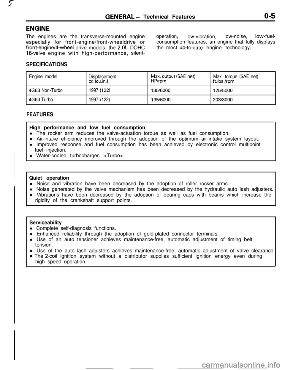
GENERAL - Technical Featureso-5ENGINE
The engines are the transverse-mounted engine
especially for front-engine/front-wheeldrive orfront-engine/4-wheel drive models, the
2.OL DOHC
16-valve engine with high-performance, silent-
operation,low-vibration,low-noise,low-fuel-
consumption features, an engine that fully displays
the most
up-todate engine technology.
SPECIFICATIONS
Engine model
Displacement
cc (cu.in.1
h$xo$put (SAE net)Max. torque (SAE net)
ft.Ibs./rpm
4G63Non-Turbo1997(122)135/6000125/5000
4663Turbo1997(122)195/6000203/3000
FEATURESHigh performance and low fuel consumption
l The rocker arm reduces the valve-actuation torque as well as fuel consumption.
l Air-intake efficiency improved through the adoption of the optimum air-intake system layout.
l Improved response and fuel consumption has been achieved by electronic control multipoint
fuel injection.
l Water-cooled turbocharger.
Quiet operation
l Noise and vibration have been decreased by the adoption of roller rocker arms.
l Noise generated by the valve mechanism has been decreased by the hydraulic auto lash adjusters.
l Vibrations have been decreased by the adoption of bearing caps with beams which increase the
rigidity of the crankshaft support points.
-Serviceability
l Complete self-diagnosis functions.
l Enhanced reliability through the adoption of gold-plated connector terminals.
l Use of an auto tensioner achieves maintenance-free, automatic adjustment of timing belt
tension.
l Use of the auto lash adjusters achieves maintenance-free, automatic adjustment of valve clearance
.o The 2coil ignition system without a distributor supplies sufficient ignition energy even during
high speed operation.
Page 10 of 391
O-6GENERAL - Technical Features
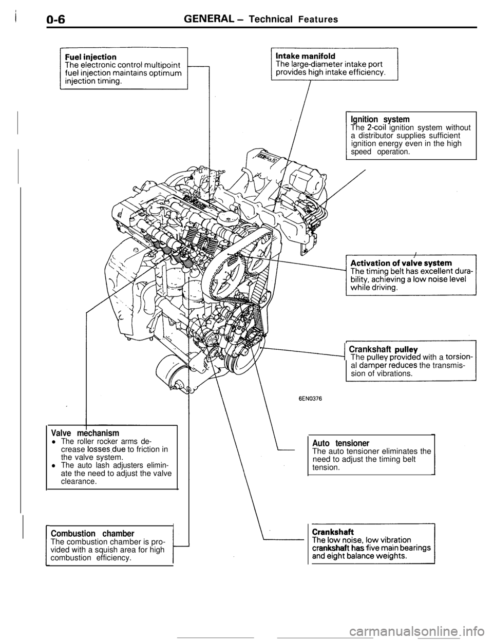
Valve mechanisml The roller rocker arms de-crease losses.due to friction in
the valve system.
l The auto lash adjusters elimin-ate the need to adjust the valve
clearance.
ICombustion chamberThe combustion chamber is pro-
vided with a squish area for high
combustion efficiency.
tJ
Ignition systemThe 2coil ignition system without
a distributor supplies sufficient
ignition energy even in the high
speed operation.
76-4 Crankshaft pu!leyThe oullev orovrded with a torsion-
al
da’mper ieduces the transmis-
sion of vibrations.
EN0376
Auto tensionerThe auto tensioner eliminates the
need to adjust the timing belt
tension.
]Icrankshaft has five marn bearings
Page 59 of 391
ELECTRICAL -Relavs, Control Units and Sensors
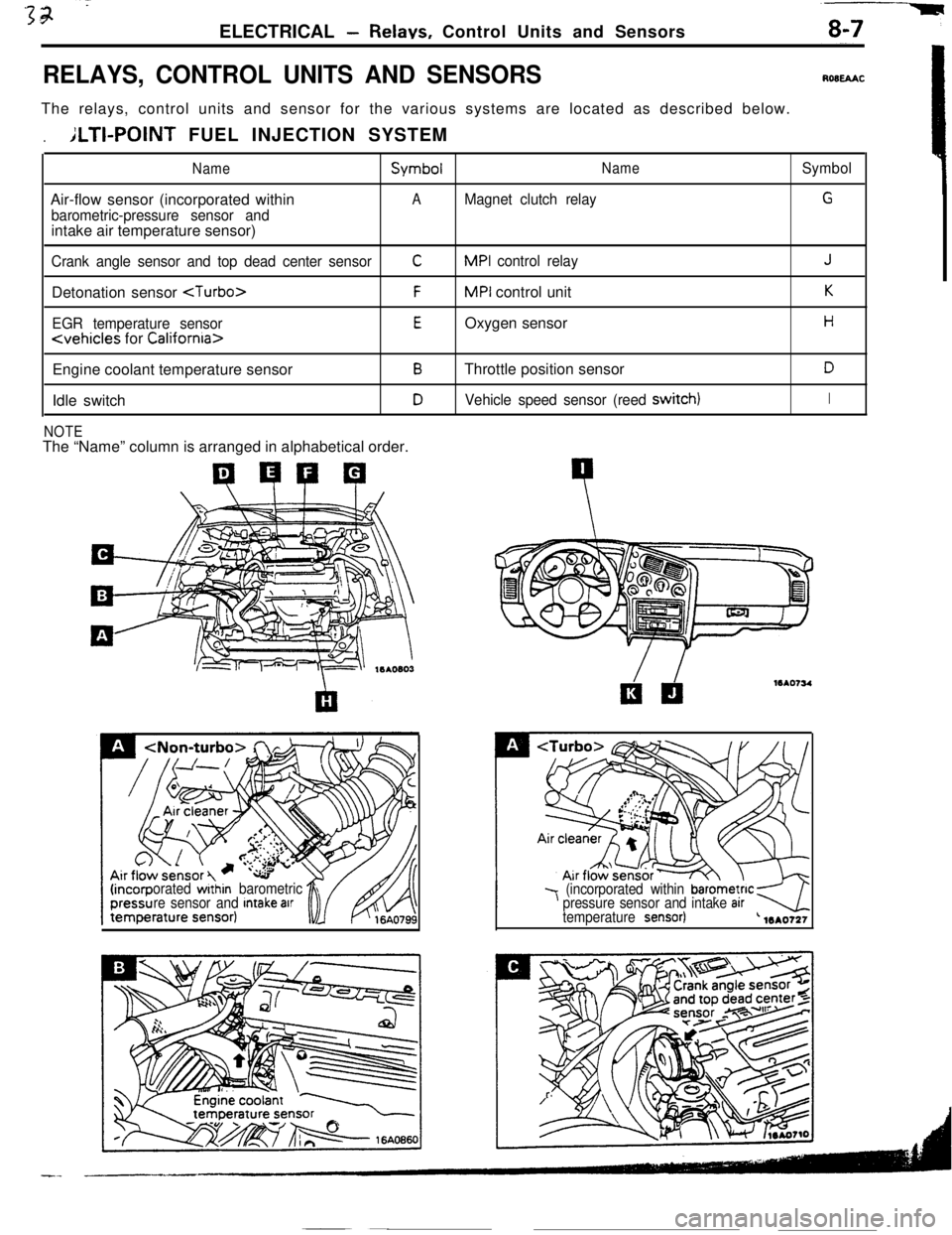
RELAYS, CONTROL UNITS AND SENSORSROBEAACThe relays, control units and sensor for the various systems are located as described below.
.ILTI-POINT FUEL INJECTION SYSTEM
NameSymbolNameSymbolAir-flow sensor (incorporated within
AMagnet clutch relayG
barometric-pressure sensor andintake air temperature sensor)
Crank angle sensor and top dead center sensorCMPI control relayJDetonation sensor
EGR temperature sensorEOxygen sensorH
Engine coolant temperature sensor
BThrottle position sensorDIdle switch
DVehicle speed sensor (reed switch)I
NOTEThe “Name” column is arranged in alphabetical order.
orated within barometric
re sensor and Intake arr7 (incorporated within barometnc kpressure sensor and intake arrtemperature sensor)-4L 1mo721
Page 70 of 391
8-18ELECTRICAL - Lighting
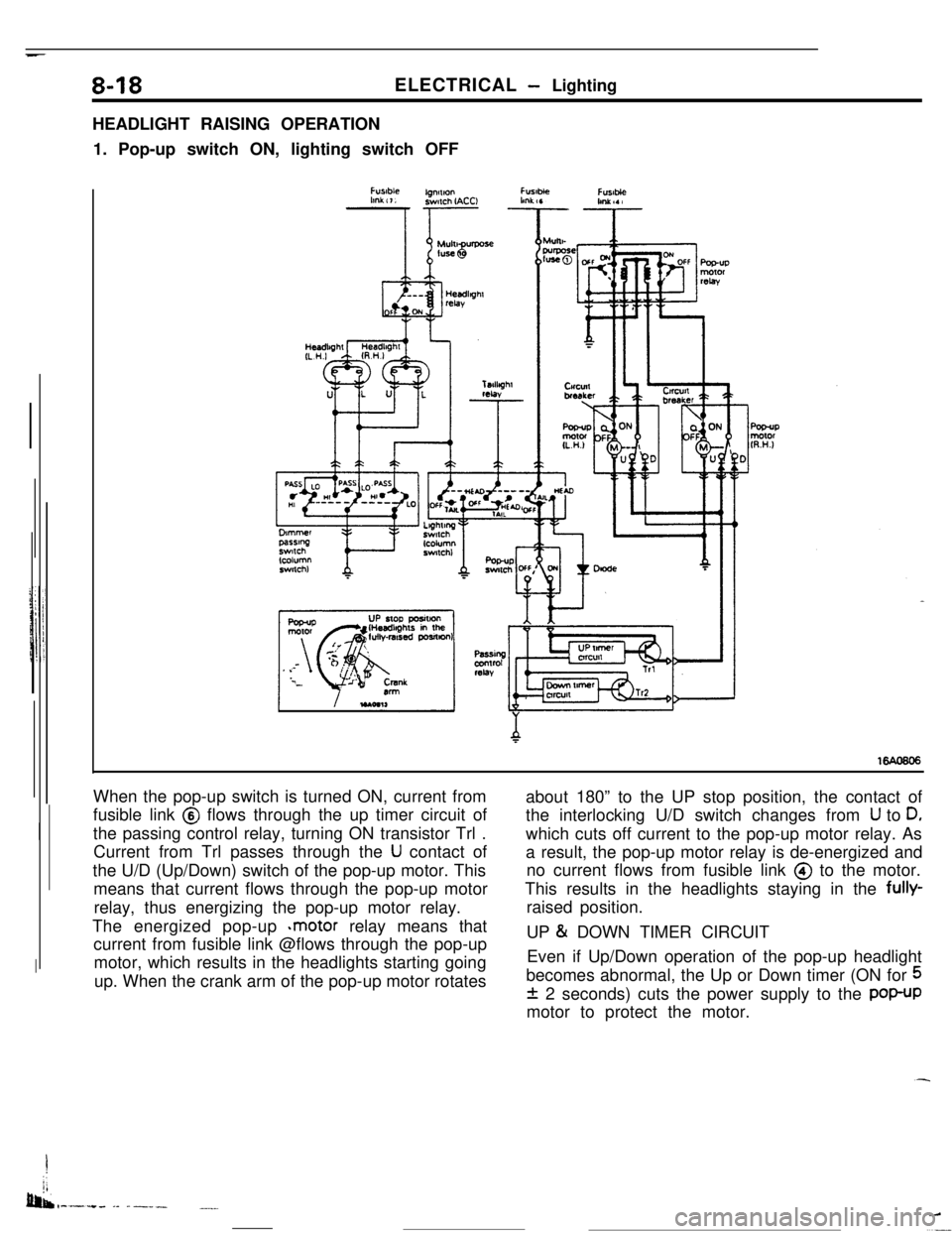
HEADLIGHT RAISING OPERATION
1. Pop-up switch ON, lighting switch OFF
When the pop-up switch is turned ON, current from
fusible link @ flows through the up timer circuit of
the passing control relay, turning ON transistor Trl .
Current from Trl passes through the
U contact of
the U/D (Up/Down) switch of the pop-up motor. This
means that current flows through the pop-up motor
relay, thus energizing the pop-up motor relay.
The energized pop-up
*motor relay means that
current from fusible link @flows through the pop-up
motor, which results in the headlights starting going
up. When the crank arm of the pop-up motor rotatesabout 180” to the UP stop position, the contact of
the interlocking U/D switch changes from
U to D,which cuts off current to the pop-up motor relay. As
a result, the pop-up motor relay is de-energized and
no current flows from fusible link @ to the motor.
This results in the headlights staying in the fully-
raised position.
UP
& DOWN TIMER CIRCUIT
Even if Up/Down operation of the pop-up headlight
becomes abnormal, the Up or Down timer (ON for
5
f 2 seconds) cuts the power supply to the POP-UPmotor to protect the motor.
I
jj
bib,-.-.+. -- ------.__
Page 72 of 391
_ -. _ -.__-ELECTRICAL
- Lighting
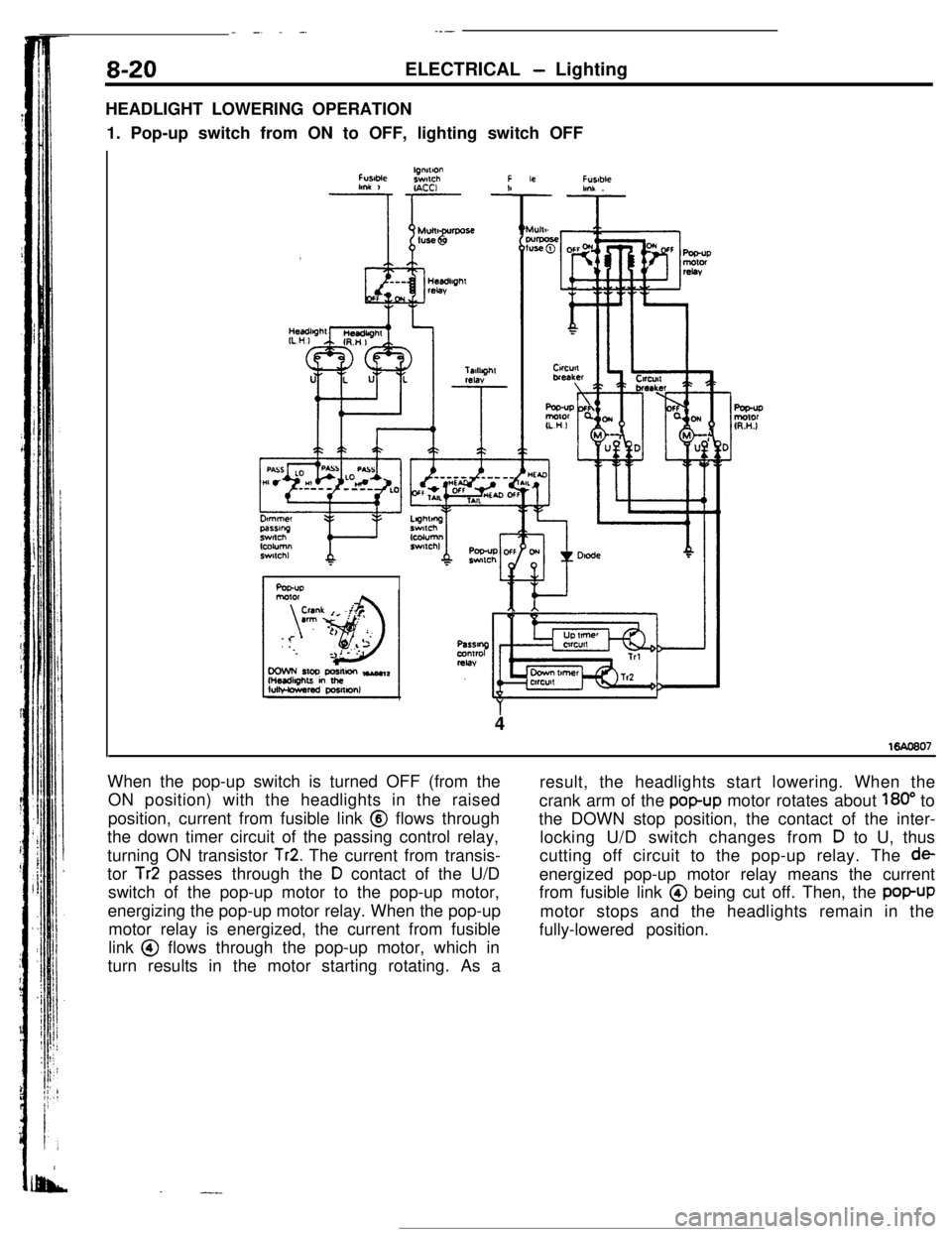
HEADLIGHT LOWERING OPERATION
1. Pop-up switch from ON to OFF, lighting switch OFF
FUslMelgnnlonswlchFlmk 1r- -!IACCI
Ar
Fusablehnk .
4
When the pop-up switch is turned OFF (from the
ON position) with the headlights in the raised
position, current from fusible link @ flows through
the down timer circuit of the passing control relay,
turning ON transistor
Tr2. The current from transis-
tor
Tr2 passes through the D contact of the U/D
switch of the pop-up motor to the pop-up motor,
energizing the pop-up motor relay. When the pop-up
motor relay is energized, the current from fusible
link @ flows through the pop-up motor, which in
turn results in the motor starting rotating. As a
.-.-result, the headlights start lowering. When the
crank arm of the
popup motor rotates about 180” to
the DOWN stop position, the contact of the inter-
locking U/D switch changes from
D to U, thus
cutting off circuit to the pop-up relay. The
deenergized pop-up motor relay means the current
from fusible link @ being cut off. Then, the
popUPmotor stops and the headlights remain in the
fully-lowered position.
Page 79 of 391
-----. _-- ___ELECTRICAL
- Engine Electrical8-27IGNITION TIMING CONTROL SYSTEM
Air flow sensor
Engtne control unit
Intake air temp. sensor
Barometric pressure sensor
Engine coolant temp. sensorIdle position switch
:+
Top dead center sensor
Crank angle sensorVehicle speed sensor
;+Ignition switch “ST” terminal
Detonation sensor for
turbo engine only
4 Power= tranststor “B”P Ignition coil
109
_
I
1
12a”- To tachometer
Terminal for engine speed detection
Terminal for ignition,timing
and idle speed adjustment
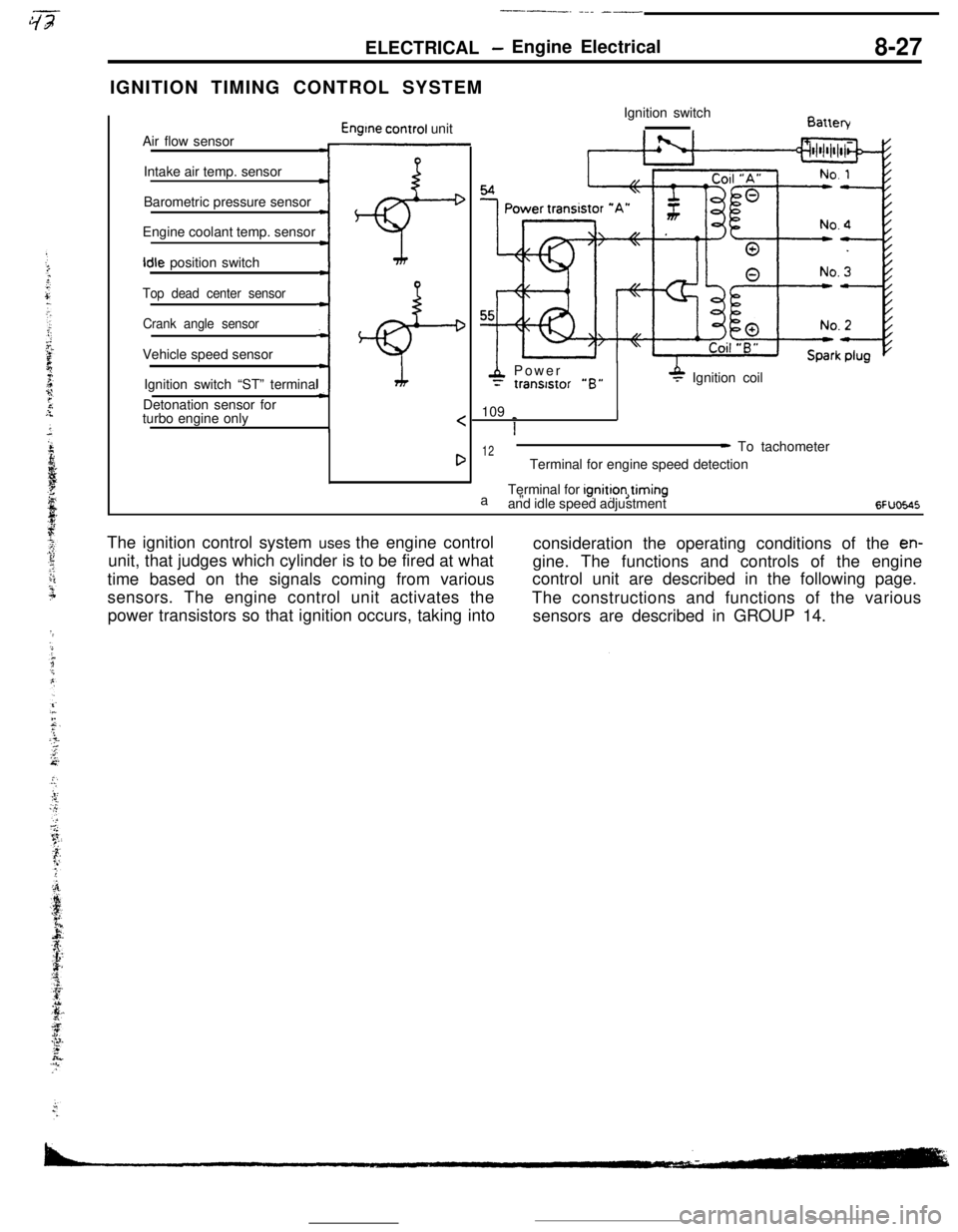
6FUoE.45The ignition control system uses the engine control
consideration the operating conditions of the
en-unit, that judges which cylinder is to be fired at what
gine. The functions and controls of the engine
time based on the signals coming from variouscontrol unit are described in the following page.
sensors. The engine control unit activates the
The constructions and functions of the various
power transistors so that ignition occurs, taking into
sensors are described in GROUP 14.
Page 81 of 391
. ,-s- ,-T,“~:~y.“‘~...:tg==ELECTRICAL
-Engine Electrical8-29Ignition Power Distribution Control
No. 1 TDC
I
No. 3 TDCNo 4TDCNo 2 TDC
‘op dead center signal,\
I1IIII
Crank angle signal
No. 1 cylinderCombustionExhaustIntakeCompres-
strokestrokestrokeslon stroke
IntakeCompression
t\
CombustionExhaust
No. 3 cyltnderstrokestroke. strokestroke
No. 4 cylinder, t\
IntakeCompressionstrokestroker$,mkbeustlonExhauststroke
Combus-No. 2 cylinder tlon
strokeintake
strokeCompresslon
stroke6EL0067
75”BTDC TI
Crank 1
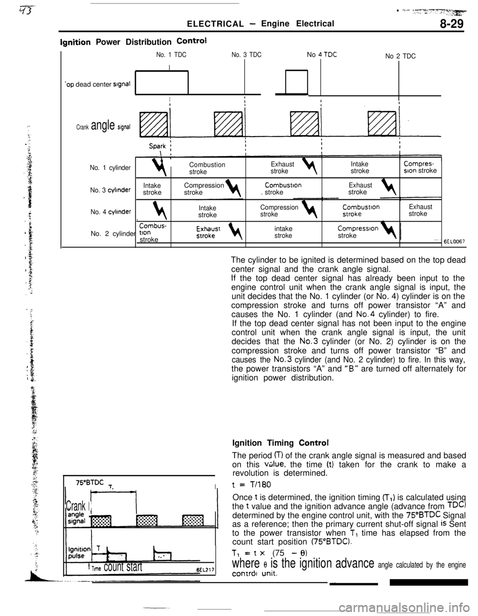
f Time count start6EL217The cylinder to be ignited is determined based on the top dead
center signal and the crank angle signal.
If the top dead center signal has already been input to the
engine control unit when the crank angle signal is input, the
unit decides that the No. 1 cylinder (or No. 4) cylinder is on the
compression stroke and turns off power transistor “A” and
causes the No. 1 cylinder (and No.4 cylinder) to fire.
If the top dead center signal has not been input to the engine
control unit when the crank angle signal is input, the unit
decides that the No.3 cylinder (or No. 2) cylinder is on the
compression stroke and turns off power transistor “B” and
causes the No.3 cylinder (and No. 2 cylinder) to fire. In this way,the power transistors “A” and
“B” are turned off alternately for
ignition power distribution.t
= T/180Once
t is determined, the ignition timing (T,) is calculated using
the t value and the ignition advance angle (advance from
TDC)determined by the engine control unit, with the
75”BTDC Signal
as a reference; then the primary current shut-off signal
is Sent
to the power transistor when
T, time has elapsed from the
count start position
(75“BTDC).Tl= t
x (75 - 9)
where 8 is the ignition advance angle calculated by the engine_, ~4 -‘*Lonrrol unlr.Ignition Timing Control
The period
(T) of the crank angle signal is measured and based
on this
v&lue, the time (t) taken for the crank to make a
revolution is determined.
Page 82 of 391
8-30ELECTRICAL - Engine Electrical
Ignition Advance Angle Control
While
cranking
Fixed angle(5”BTD.C)Engme coolantBarometnc‘-Intake air 1temperaturepressuretemperaturesensorsensor, sensor
Dunng normal operatlon4i+
Advance angle map valueEngine
coolantBarometricIntake airaccording to engine speed4and intake air volumetemperature- pressure__c temperature 4
correctioncorrectloncorrectton
Durtng ignition tlmmg adjustment
Fixed angle(5”BTDC)
c
=ower transistor
-$To ignition
coil
s
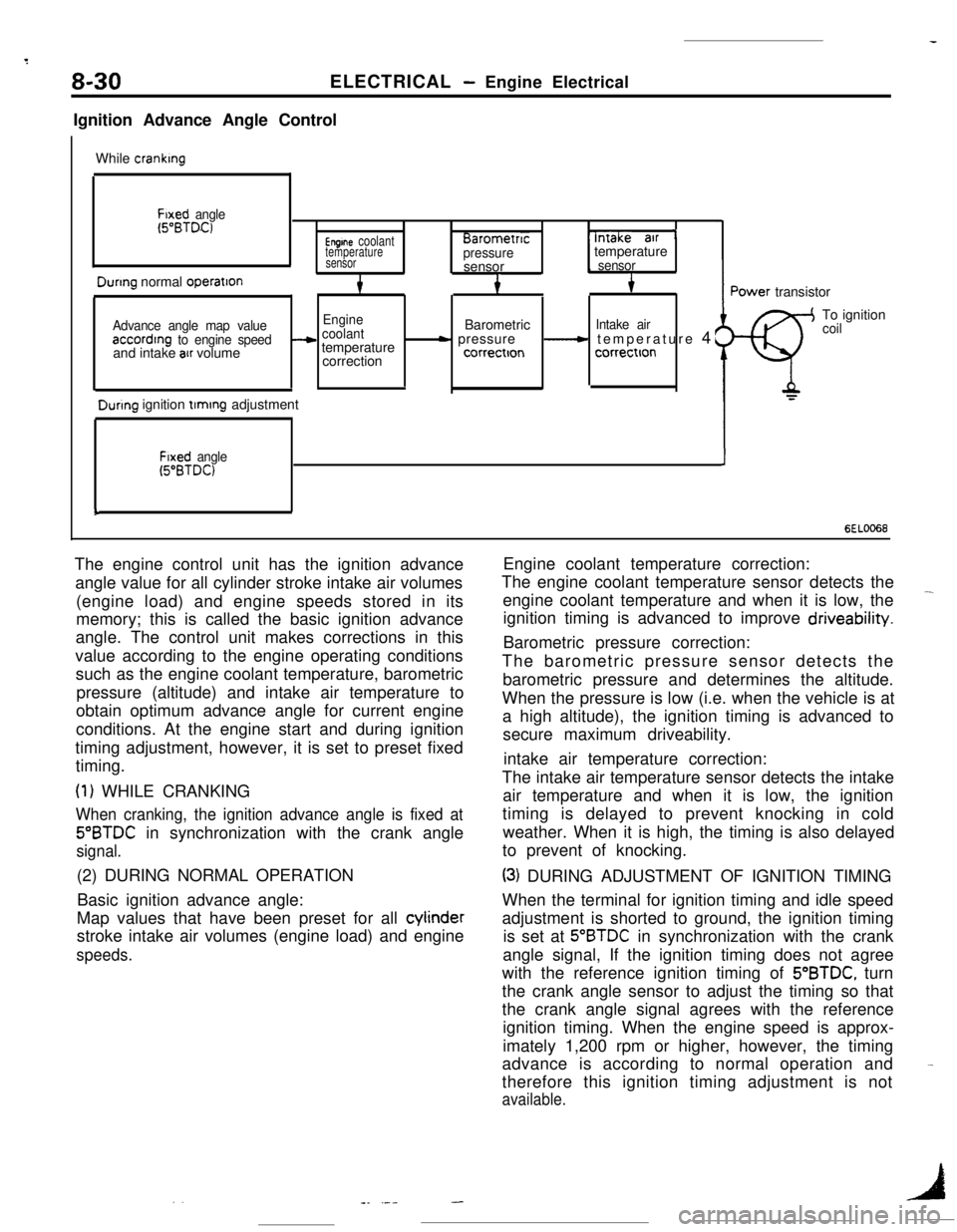
6EL0066The engine control unit has the ignition advance
angle value for all cylinder stroke intake air volumes
(engine load) and engine speeds stored in its
memory; this is called the basic ignition advance
angle. The control unit makes corrections in this
value according to the engine operating conditions
such as the engine coolant temperature, barometric
pressure (altitude) and intake air temperature to
obtain optimum advance angle for current engine
conditions. At the engine start and during ignition
timing adjustment, however, it is set to preset fixed
timing.
(1) WHILE CRANKING
When cranking, the ignition advance angle is fixed at
5”BTDC in synchronization with the crank angle
signal.(2) DURING NORMAL OPERATION
Basic ignition advance angle:
Map values that have been preset for all cylinder
stroke intake air volumes (engine load) and engine
speeds.Engine coolant temperature correction:
The engine coolant temperature sensor detects the
engine coolant temperature and when it is low, the
-ignition timing is advanced to improve driveability.
Barometric pressure correction:
The barometric pressure sensor detects the
barometric pressure and determines the altitude.
When the pressure is low (i.e. when the vehicle is at
a high altitude), the ignition timing is advanced to
secure maximum driveability.
intake air temperature correction:
The intake air temperature sensor detects the intake
air temperature and when it is low, the ignition
timing is delayed to prevent knocking in cold
weather. When it is high, the timing is also delayed
to prevent of knocking.
(3) DURING ADJUSTMENT OF IGNITION TIMING
When the terminal for ignition timing and idle speed
adjustment is shorted to ground, the ignition timing
is set at
5”BTDC in synchronization with the crank
angle signal, If the ignition timing does not agree
with the reference ignition timing of 5’BTDC, turn
the crank angle sensor to adjust the timing so that
the crank angle signal agrees with the reference
ignition timing. When the engine speed is approx-
imately 1,200 rpm or higher, however, the timing
advance is according to normal operation and
therefore this ignition timing adjustment is not
available.
-
. .1-_ .---
Page 83 of 391
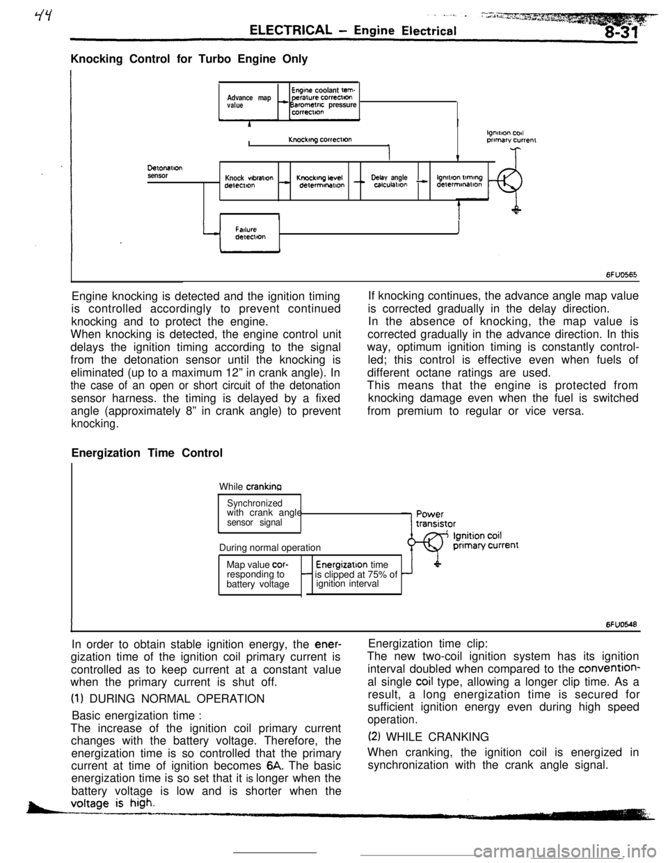
Knocking Control for Turbo Engine OnlyEngine coolant tern.Advance mapperarure correctton
value- Barometric pressurecorrectton
DelonaIlon
sensorI
lgnmon codKnockmg correcllonprimary currenr
v
Knock wbral+onKnockmg LevelDelay anglelgnmon tlmtngdetemon- delermonmon - calculallon - derermmatlon
II
Y
FatlureIdeIeclton
6FUO565Engine knocking is detected and the ignition timing
is controlled accordingly to prevent continued
knocking and to protect the engine.
When knocking is detected, the engine control unit
delays the ignition timing according to the signal
from the detonation sensor until the knocking is
eliminated (up to a maximum 12” in crank angle). In
the case of an open or short circuit of the detonationsensor harness. the timing is delayed by a fixed
angle (approximately 8” in crank angle) to prevent
knocking.Energization Time Control
While
crankinaIf knocking continues, the advance angle map value
is corrected gradually in the delay direction.
In the absence of knocking, the map value is
corrected gradually in the advance direction. In this
way, optimum ignition timing is constantly control-
led; this control is effective even when fuels of
different octane ratings are used.
This means that the engine is protected from
knocking damage even when the fuel is switched
from premium to regular or vice versa.
Synchronizedwith crank angle
sensor signalcDuring normal operation
Map value
cor-Energizatlon time
responding to- is clipped at 75% of
battery voltageignition interval
IIn order to obtain stable ignition energy, the
ener-gization time of the ignition coil primary current is
controlled as to keep current at a constant value
when the primary current is shut off.
(1) DURING NORMAL OPERATION
Basic energization time
:The increase of the ignition coil primary current
changes with the battery voltage. Therefore, the
energization time is so controlled that the primary
current at time of ignition becomes
6A. The basic
energization time is so set that it is longer when the
battery voltage is low and is shorter when the
6FUO548Energization time clip:
The new two-coil ignition system has its ignition
interval doubled when compared to the convention-
al single
coil type, allowing a longer clip time. As a
result, a long energization time is secured for
sufficient ignition energy even during high speed
operation.
(2) WHILE CRANKING
When cranking, the ignition coil is energized in
synchronization with the crank angle signal.
-
Page 87 of 391
=--Y
jl
1 /
i "
_. ---“._ _ _ ._ ..-..+_LI_y_--- -
9-2ENGINE- General Information
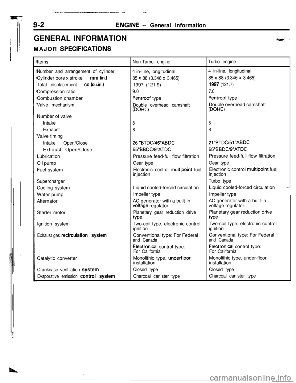
GENERAL INFORMATION
MAJOR
SPEClFlCATiONS
Row- -
Items
Number and arrangement of cylinderCylinder bore x stroke
mm (in.)
Total displacementcc (cu.in.1Compression ratio
Combustion chamber
Valve mechanismNumber of valve
Intake
Exhaust
Valve timing
IntakeOpen/CloseExhaust Open/Close
Lubrication
Oil pump
Fuel system
SuperchargerCooling system
Water pump
Alternator
Starter motor
Ignition system
Exhaust gas recirculation systemCatalytic converter
Crankcase ventilation system
Evaporative emission control system
Non-Turbo engineTurbo engine4 in-line, longitudinal
4 in-line, longitudinal
85 x
88 (3.346 x 3.465)85 x 88 (3.346 x 3.465)1997 (121.9)
1997 (121.7)
9.07.8
Pentroof typePentroof type
Double overhead camshaftDouble overhead camshaft
(DOHC)(DOHC)
88
88
26 “BTDU46”ABDC21”BTDC/Sl”ABDC56BBDUS”ATDC55”BBDUS”ATDC
Pressure feed-full flow filtrationPressure feed-full flow filtration
Gear typeGear type
Electronic control multipoint
fuelElectronic control multipoint fuel
injectioninjection
Turbo typeLiquid cooled-forced circulationLiquid cooled-forced circulation
-Impeller typeImpeller type
AC generator with a built-involtage regulatorAC generator with a built-in
voltage regulator
Planetary gear reduction drivePlanetary gear reduction drivetype
Two-coil type, electronic controlTwo-coil type, electronic control
ignitionignition
Conventional type: For FederalConventional type: For Federal
and Canadaand Canada
Electronical control type:Electronical control type:
For CaliforniaFor CaliforniaMonolithic type,
under-floorMonolithic type, under-floor
installationinstallation
Closed typeClosed type
Charcoal canister typeCharcoal canister type
I