fuel filter MITSUBISHI ECLIPSE 1990 Service Manual
[x] Cancel search | Manufacturer: MITSUBISHI, Model Year: 1990, Model line: ECLIPSE, Model: MITSUBISHI ECLIPSE 1990Pages: 391, PDF Size: 15.27 MB
Page 118 of 391
14-6FUEL SYSTEM -Fuel Supply and Fuel Pressure Control
intake manifold/I\
Engine
Fuel
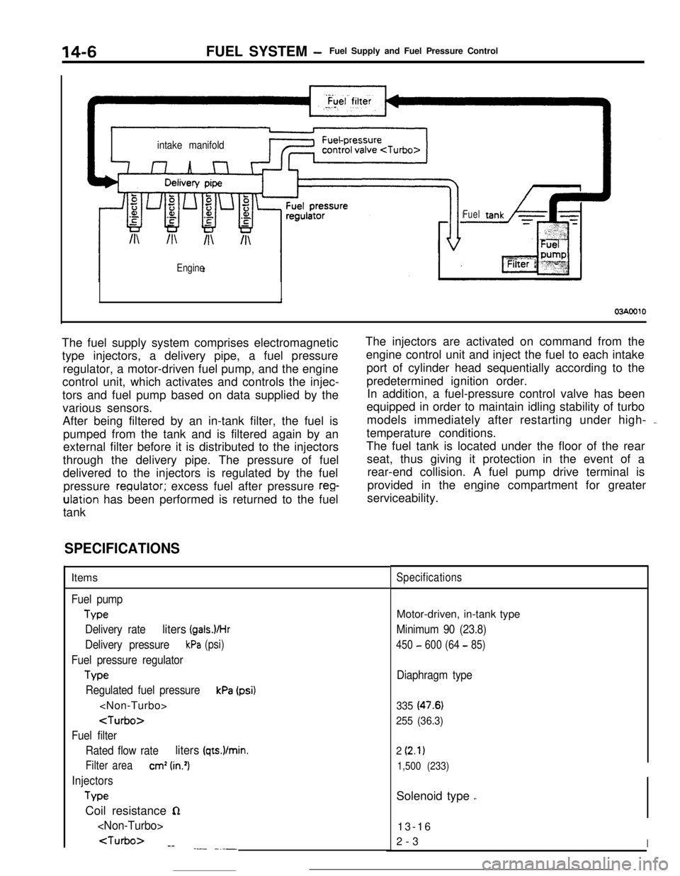
03AOOlOThe fuel supply system comprises electromagnetic
type injectors, a delivery pipe, a fuel pressure
regulator, a motor-driven fuel pump, and the engine
control unit, which activates and controls the injec-
tors and fuel pump based on data supplied by the
various sensors.
After being filtered by an in-tank filter, the fuel is
pumped from the tank and is filtered again by an
external filter before it is distributed to the injectors
through the delivery pipe. The pressure of fuel
delivered to the injectors is regulated by the fuel
pressure
reoulator; excess fuel after pressure reg-ulation has been performed is returned to the fuel
tankThe injectors are activated on command from the
engine control unit and inject the fuel to each intake
port of cylinder head sequentially according to the
predetermined ignition order.
In addition, a fuel-pressure control valve has been
equipped in order to maintain idling stability of turbo
models immediately after restarting under high- -
temperature conditions.
The fuel tank is located under the floor of the rear
seat, thus giving it protection in the event of a
rear-end collision. A fuel pump drive terminal is
provided in the engine compartment for greater
serviceability.
-
SPECIFICATIONSItems
Fuel pump
Type
Delivery rate
liters (gals.VHr
Delivery pressurekPa (psi)
Fuel pressure regulator
Tvw
Regulated fuel pressurekPa (psi)
Fuel filter
Rated flow rate
liters (qts.)/min.
Filter areacm’ (in.‘)
Injectors
TypeCoil resistance
n
--
.- -_-_
SpecificationsMotor-driven, in-tank type
Minimum 90 (23.8)
450 - 600 (64 - 85)
Diaphragm type
335 (47.6)
255 (36.3)
2
(2.1)
1,500 (233)Solenoid type
,.13-16
2-3
I
Page 119 of 391
FUEL SYSTEM -Fuel Supply and Fuel Pressure Control14-7FUEL TANK
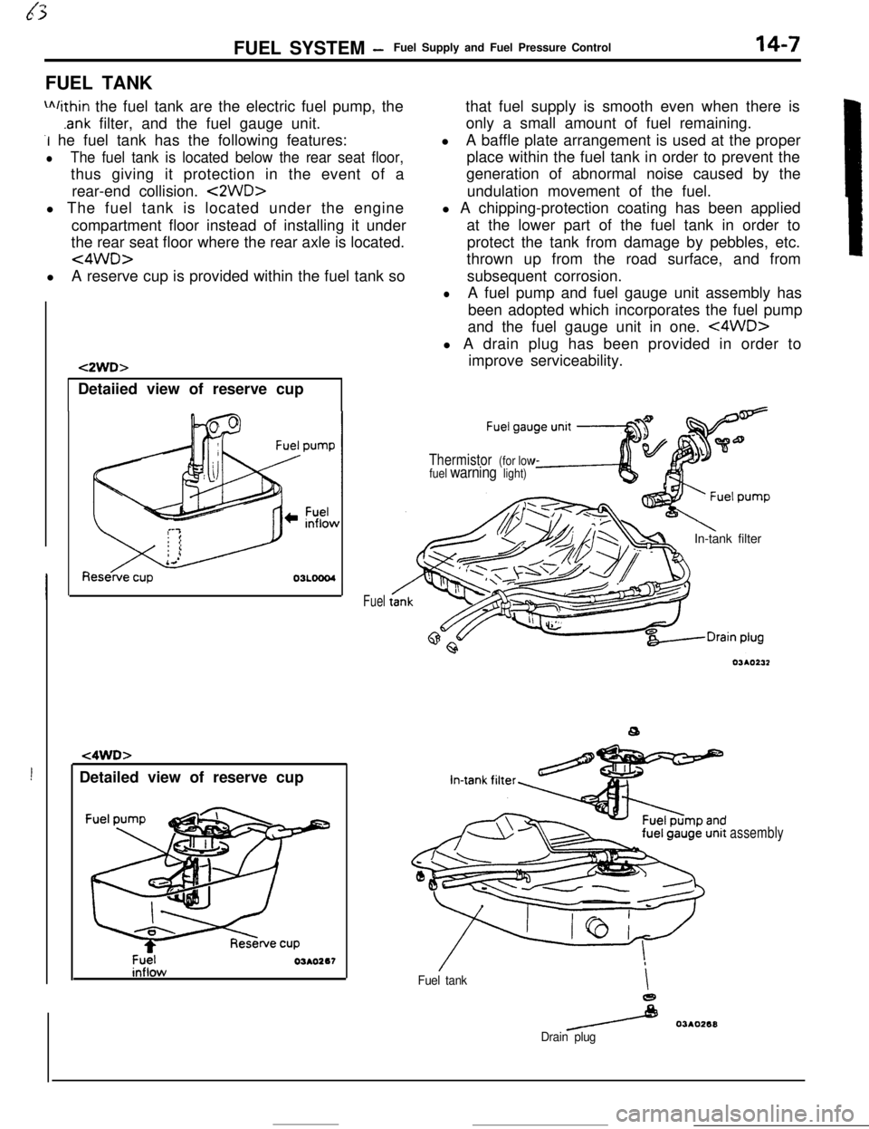
m/ithin the fuel tank are the electric fuel pump, the
.ank filter, and the fuel gauge unit.
-I he fuel tank has the following features:
lThe fuel tank is located below the rear seat floor,thus giving it protection in the event of a
rear-end collision.
<2WD>l The fuel tank is located under the engine
compartment floor instead of installing it under
the rear seat floor where the rear axle is located.
<4WD>lA reserve cup is provided within the fuel tank so
!Detailed view of reserve cup
t2WD>Detaiied view of reserve cup
t4WD>
Fuel03AO267
Fuelthat fuel supply is smooth even when there is
only a small amount of fuel remaining.
lA baffle plate arrangement is used at the proper
place within the fuel tank in order to prevent the
generation of abnormal noise caused by the
undulation movement of the fuel.
l A chipping-protection coating has been applied
at the lower part of the fuel tank in order to
protect the tank from damage by pebbles, etc.
thrown up from the road surface, and from
subsequent corrosion.
lA fuel pump and fuel gauge unit assembly has
been adopted which incorporates the fuel pump
and the fuel gauge unit in one.
<4WD>l A drain plug has been provided in order to
improve serviceability.
Thermistor (for low
fuel warning light)In-tank filter
Fuel tankI
e
/ 03AO268
Drain plug
assembly
Page 121 of 391
FUEL SYSTEM -Fuel Supply and Fuel Pressure Control14-9
03Poo4:Diaphragm
from intake
4Fuel from delivery pipe
4m
B(42.7)QQ
2
sl -196 2
(26.4) g
t
$!a d
9
0)Positive5 z‘. pressure
(E.2)
w
FUEL FILTERA high-pressure type filter is installed at the delivery end of the
fuel pump.
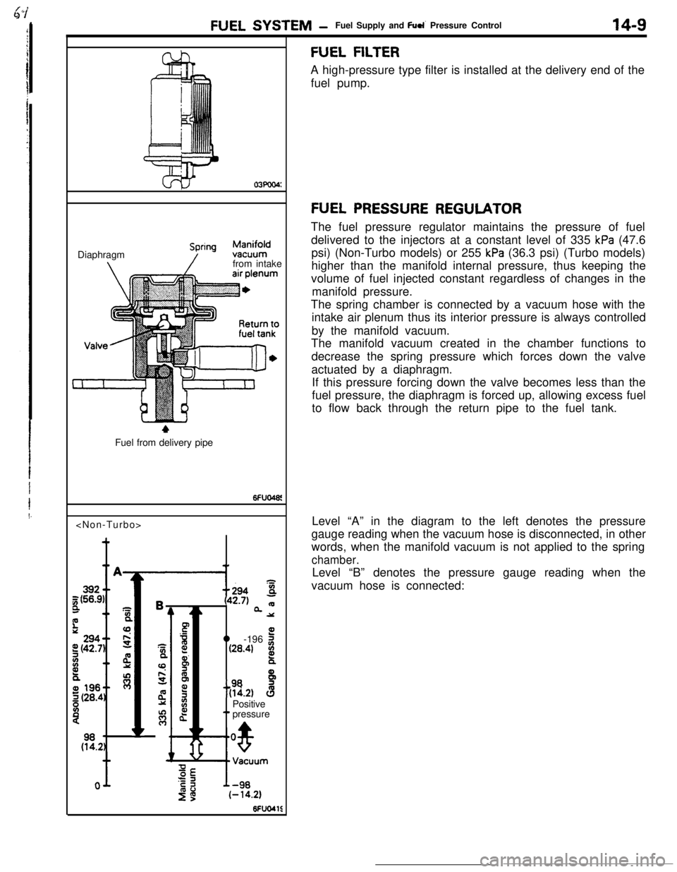
FUEL PRESSURE REGULATORThe fuel pressure regulator maintains the pressure of fuel
delivered to the injectors at a constant level of 335
kPa (47.6
psi) (Non-Turbo models) or 255
kPa (36.3 psi) (Turbo models)
higher than the manifold internal pressure, thus keeping the
volume of fuel injected constant regardless of changes in the
manifold pressure.
The spring chamber is connected by a vacuum hose with the
intake air plenum thus its interior pressure is always controlled
by the manifold vacuum.
The manifold vacuum created in the chamber functions to
decrease the spring pressure which forces down the valve
actuated by a diaphragm.
If this pressure forcing down the valve becomes less than the
fuel pressure, the diaphragm is forced up, allowing excess fuel
to flow back through the return pipe to the fuel tank.
Level “A” in the diagram to the left denotes the pressure
gauge reading when the vacuum hose is disconnected, in other
words, when the manifold vacuum is not applied to the spring
chamber.Level “B” denotes the pressure gauge reading when the
vacuum hose is connected:
Page 122 of 391
14-10
INJECTORFUEL SYSTEM
-Fuel Supply and Fuel Pressure Control
Intake port
lelivelYPipte
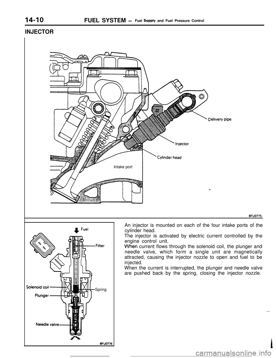
,FilterSpringAn injector is mounted on each of the four intake ports of the
cylinder head.
The injector is activated by electric current controlled by the
engine control unit.Wh-en current flows through the solenoid coil, the plunger and
needle valve, which form a single unit are magnetically
attracted, causing the injector nozzle to open and fuel to be
injected.When the current is interrupted, the plunger and needle valve
are pushed back by the spring, closing the injector nozzle.
Page 137 of 391

FUEL SYSTEM - Sensors14-25Terminal for
ignition timing
adjustment
l-l6FUO51:7
W$ht(/.
Piezo-electncelements
I6FUOSlO
DetonationEngine control
unit
sensor
I-
I t i A-- >--t.--‘-3 -
wt4rlIGNITION TlMlNG ADJUSTMENT TERMINAL
This terminal
is used when adjusting the basic ignition timing or
basic idle speed.
When this terminal is shorted to ground, the engine control unit
cancels the
ignition timing control and idle speed control, and
sets the ignition
timing and idle speed control servos in their
adjusting mode.
For the basic idle speed adjustment, the diagnosis terminal is
also shorted to ground.
DETONATION SENSOR
The detonation sensor is installed at a position where it can
detect, with a high degree of precision, knocking generated at
each cylinder; it detects cylinder block vibrations caused by
knocking, and outputs voltage proportional to the magnitude of
those vibrations.
Because cylinder block vibrations caused by knocking vary
from engine to engine, the engine control unit passes this
through a frequncy filter, detecting only the knocking, thus
resulting in a spark retardation of the ignition timing that
corresponds to the strength of the knocking.
Page 141 of 391
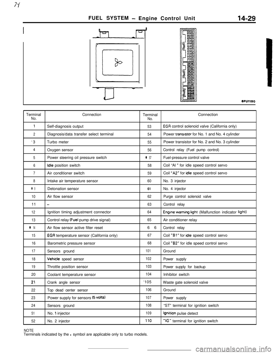
FUEL SYSTEM- Engine Control Unit14-29
SFUllSOTerminal
ConnectionTerminalConnectionNo.
No.
1Self-diagnosis output53EGR control solenoid valve (California only)
2Diagnosis/data transfer select terminal54Power transrstor for No. 1 and No. 4 cylinder
‘3Turbo meter
55Power transistor for No. 2 and No. 3 cylinder
4Oxygen sensor56Control relay (Fuel pump control)
5Power steering oil pressure switchl 57Fuel-pressure control valve
6Idle position switch58Coil “Al ” for idle speed control servo
7Air conditioner switch59Coil “A2” for idle speed control servo
8Intake air temperature sensor60No. 3 injector
l 9Detonation sensor61No. 4 injector
10Air flow sensor62Purge control solenoid valve11
-63Control relay
12Ignition timing adjustment connector64Engine warning irght (Malfunction indicator light)
13Control relay (Fuel pump drive signal)65Air conditioner relay
l 14Air flow sensor active filter reset66Control relay
15EGR temperature sensor (California only)67Coil “Bl ” for idle speed control servo
16Barometric pressure sensor68Coil “B2” for idle speed control servo
17Sensors ground101Ground
18Vehicle speed sensor102Power supply
19Throttle position sensor103Power supply for backup
20Coolant temperature sensor
104Inhibitor switch
21Crank angle sensor‘105
Waste gate solenoid valve
22Top dead center sensor106Ground
23Power supply for sensors (5 volts)107Power supply
24Sensors ground108“ST” terminal for ignition switch
51No. 1 injector109Ignition pulse detect
52No. 2 injector170“IG ” terminal for ignition switch
NOTETerminals indicated by the l symbol are applicable only to turbo models.
Page 146 of 391
-
14-34FUEL SYSTEM - Fuel Injection Control
TDC sensorAir flow sensor
I
Reading of input signal1
I ,,
uOperation mode decisionOperation mode decision data
I rBasic valve opening time data
Enginecontrol unitInjector activation time control
Injector activation pulse generationControl factor data of
engine coolant temperature,
intake air temperature and
barometric pressure, etc.
Injector1
6FUO766Needle valveFilter
Connector
Solenoid coil
Plunger
-4
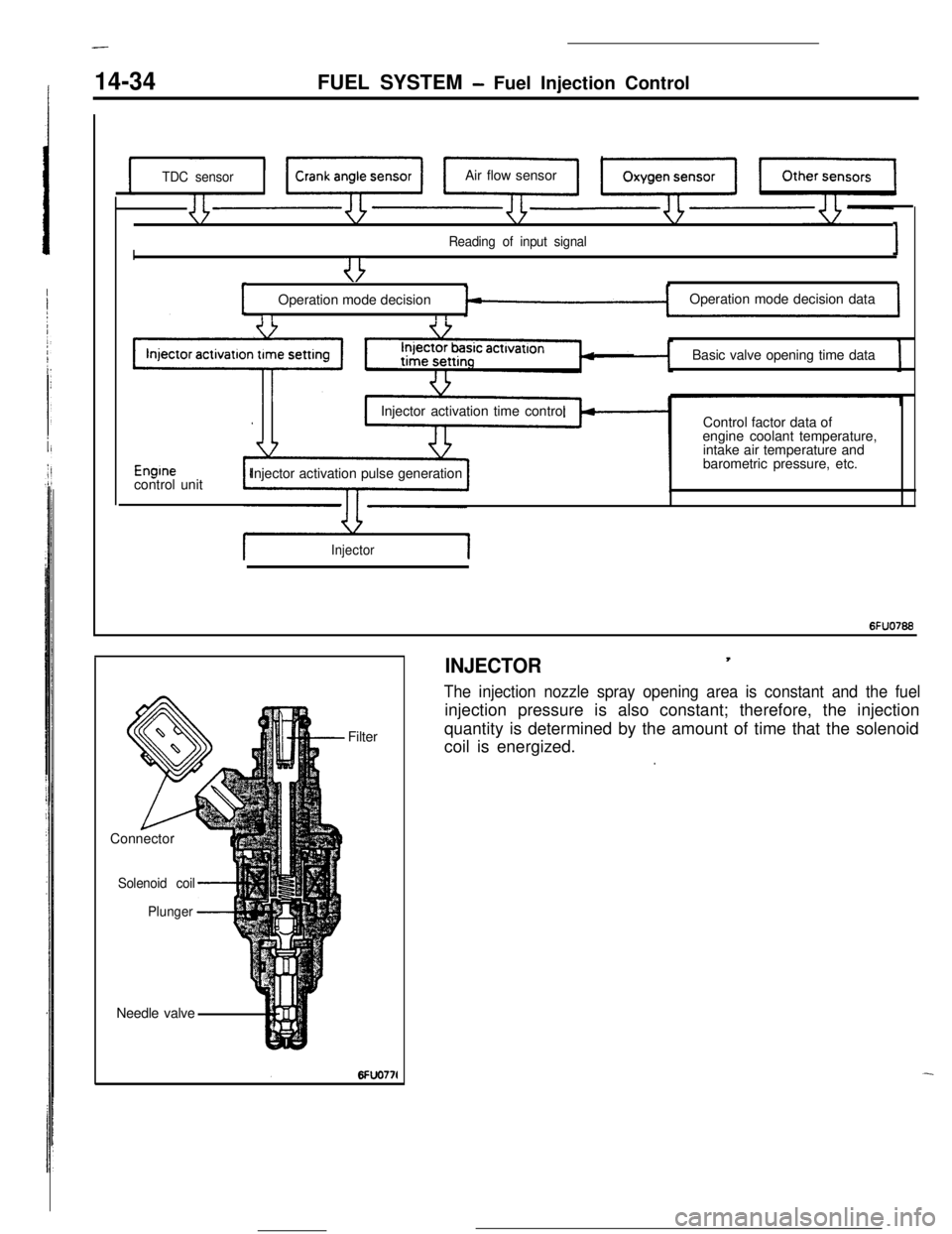
INJECTOR,
The injection nozzle spray opening area is constant and the fuelinjection pressure is also constant; therefore, the injection
quantity is determined by the amount of time that the solenoid
coil is energized.
.
Page 169 of 391
FUEL SYSTEMAir Flow Sensor (AFSI Filter Reset Control
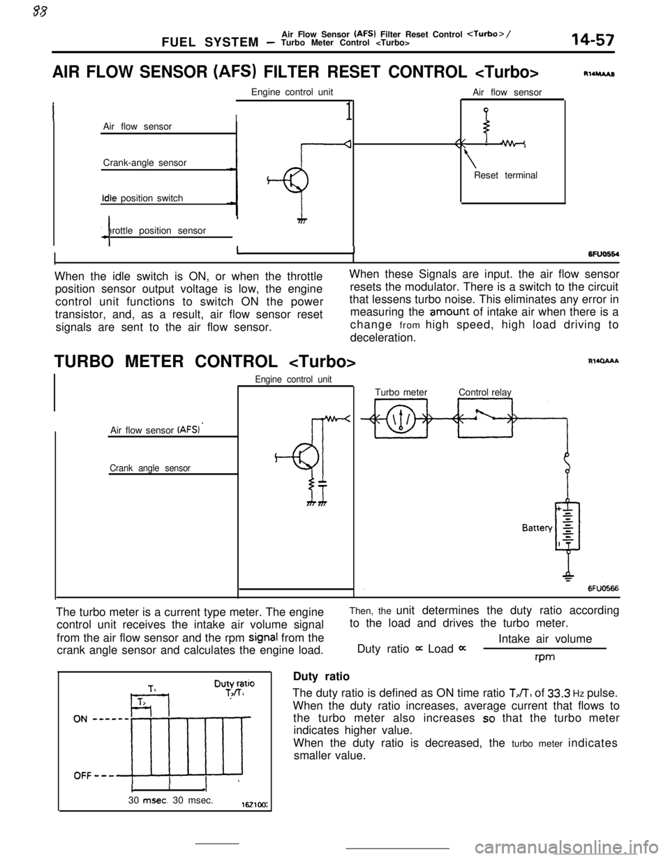
AIR FLOW SENSOR (AFS) FILTER RESET CONTROL
I1Air flow sensor
Crank-angle sensorIdle position switch
Throttle position sensor
4Air flow sensor
//\\ -
\Reset terminal
RllruAs
6FlJo664I11When the idle switch is ON, or when the throttleWhen these Signals are input. the air flow sensor
position sensor output voltage is low, the engineresets the modulator. There is a switch to the circuit
control unit functions to switch ON the powerthat lessens turbo noise. This eliminates any error in
transistor, and, as a result, air flow sensor resetmeasuring the
.amount of intake air when there is a
signals are sent to the air flow sensor.change from high speed, high load driving to
deceleration.
TURBO METER CONTROL
Air flow sensor
(AFSI ’
Crank angle sensorEngine control unit
BT
Rl4QAAATurbo meterControl relay
The turbo meter is a current type meter. The engine
control unit receives the intake air volume signal
from the air flow sensor and the rpm
signal from the
crank angle sensor and calculates the engine load.Then, the unit determines the duty ratio according
to the load and drives the turbo meter.
Intake air volume
Duty ratio
it Load 0:rwDuty ratio
The duty ratio is defined as ON time ratio
TJT, of 33.3 Hz pulse.
When the duty ratio increases, average current that flows to
the turbo meter also increases
so that the turbo meter
indicates higher value.
When the duty ratio is decreased, the turbo meter indicates
smaller value.
cI30
msec. 30 msec.1621cm:
Page 385 of 391
__..--. -._ _^__. __--- -._ _..EMISSION CONTROL SYSTEMS
- Evaporative Emission Control Svsvem25-l 1
,VAPORATlVE EMISSION CON-
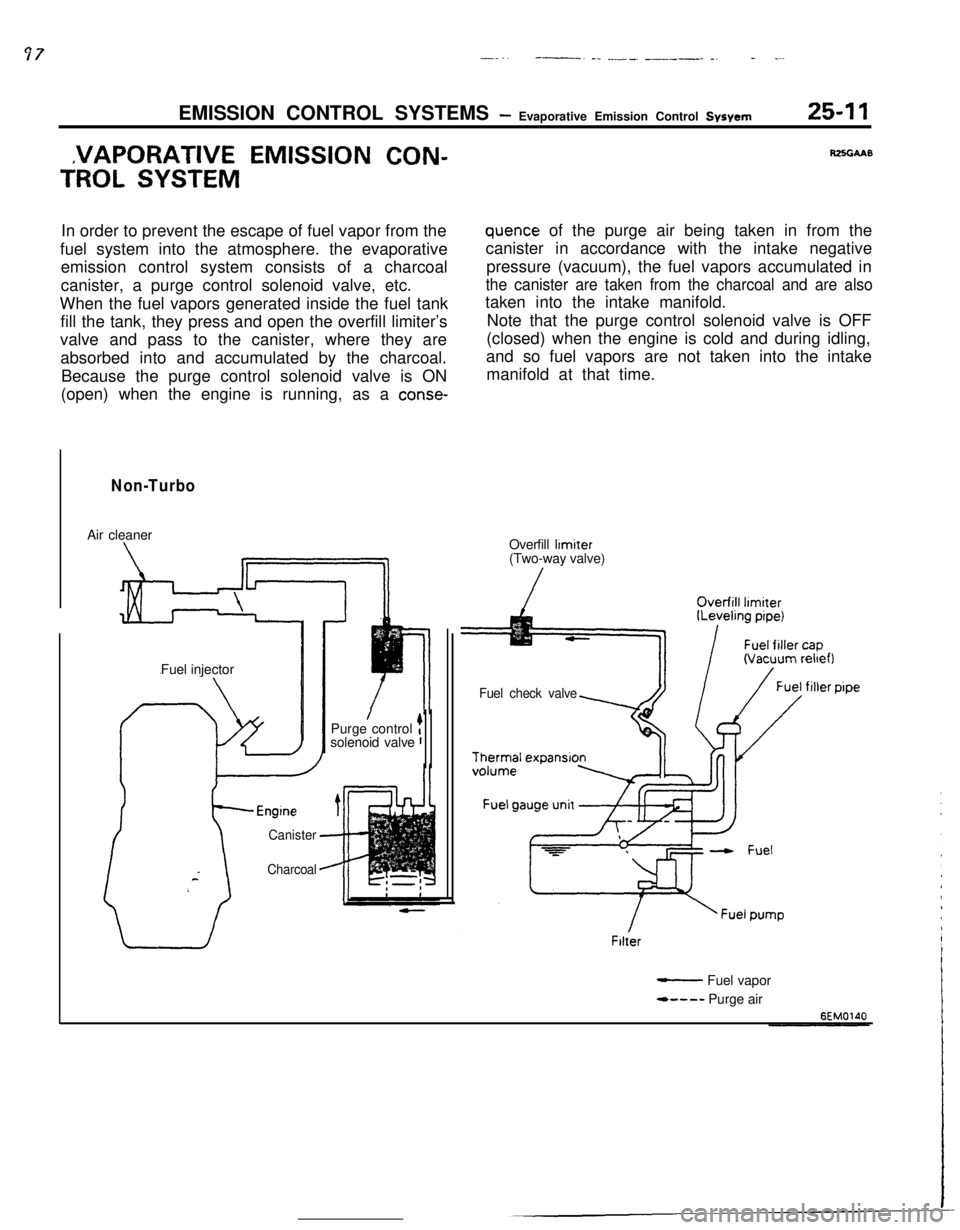
TROL SYSTEMIn order to prevent the escape of fuel vapor from the
fuel system into the atmosphere. the evaporative
emission control system consists of a charcoal
canister, a purge control solenoid valve, etc.
When the fuel vapors generated inside the fuel tank
fill the tank, they press and open the overfill limiter’s
valve and pass to the canister, where they are
absorbed into and accumulated by the charcoal.
Because the purge control solenoid valve is ON
(open) when the engine is running, as a
conse-
Non-TurboAir cleaner
Fuel injector
Canister
Charcoal
/Purge control tsolenoid valve r
RZSGAAB
quence of the purge air being taken in from the
canister in accordance with the intake negative
pressure (vacuum), the fuel vapors accumulated in
the canister are taken from the charcoal and are alsotaken into the intake manifold.
Note that the purge control solenoid valve is OFF
(closed) when the engine is cold and during idling,
and so fuel vapors are not taken into the intake
manifold at that time.
Overfill
limiter(Two-way valve)
Fuel check valveFilter
- Fuel vapor
*---- Purge air
Page 386 of 391
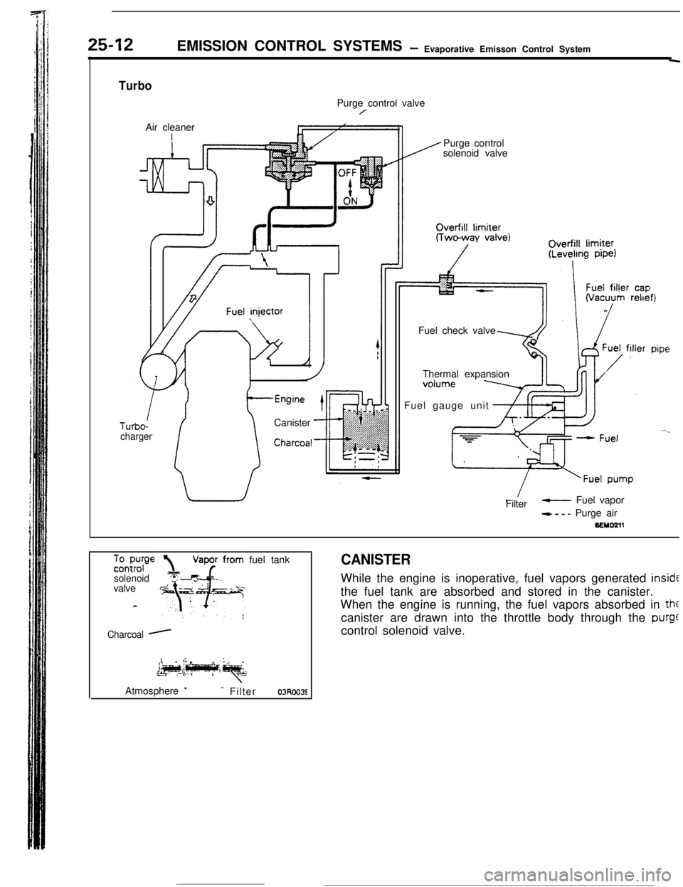
25-12EMISSION CONTROL SYSTEMS- Evaporative Emisson Control System-
TurboPurge control valve
/Air cleaner
Canister
-Charcoal-ITurbo-
chargerPurge control
solenoid valve
Fuel check valve
Thermal expansion
Fuel gauge unit
Filter
- Fuel vapor
- - - - Purge air
BEMO211
%-E?”solenoidvalve
Charcoal -fuel tank
CANISTERWhile the engine is inoperative, fuel vapors generated
insidEthe fuel tank are absorbed and stored in the canister.
When the engine is running, the fuel vapors absorbed in
thfcanister are drawn into the throttle body through the
purgecontrol solenoid valve.
Atmosphere
L- Filter03Roo3E