fuse MITSUBISHI ECLIPSE 1990 Service Manual
[x] Cancel search | Manufacturer: MITSUBISHI, Model Year: 1990, Model line: ECLIPSE, Model: MITSUBISHI ECLIPSE 1990Pages: 391, PDF Size: 15.27 MB
Page 54 of 391
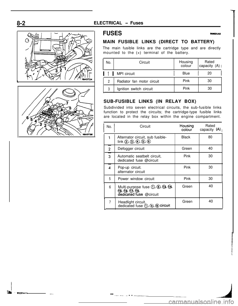
8-2
IBlueI20
L
SUB-FUSIBLE LINKS (IN RELAY BOX)
I I
No. CircuitHcyyRated
(A)I
0, 0, @, 0, @
Defogger circuit
1
6 Multi-purpose fuse 0. @. 0. @.Green 40
!Fed%$?&e @circuit1
7 Headlight circuit.0. @I. @circuitL
Ib&i -e?z5mm..-_-- -.--- --..._ . . __-___-----_4
Page 55 of 391
ELECTRICAL - Fuses8-3q
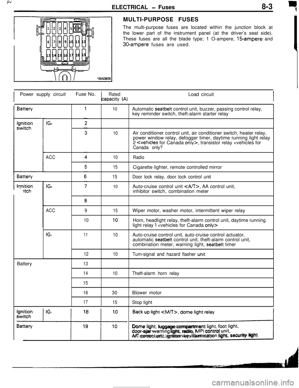
rMULTI-PURPOSE FUSES
The multi-purpose fuses are located within the junction block at
the lower part of the instrument panel (at the driver’s seat side).
These fuses are all the blade type; 1 O-ampere, 15-ampere and
30-ampere fuses are used.
IPower supply circuitFuse No.
RatedLoad circuitapacity
(A)IBattery
t-lonition,itchBattery
IGz
ACC
IG,
10
10
10
15
15
10Automatic seatbelt control unit, buzzer, passing control relay,
key reminder switch, theft-alarm starter relay
Air conditioner control unit, air conditioner switch, heater relay,
power window relay, defogger timer, daytime running light relay
2
Door lock relay, door lock control unitAuto-cruise control unit
, AA control unit,
inhibitor switch, combination meter
ACC
IGI9
1011
12
1315
10
10
10Wiper motor, washer motor, intermittent wiper relay
Horn, headlight relay, theft-alarm control unit, daytime running
light relay
1
automatic seatbelt control unit, theft-alarm control unit,
combination meter, warning light, seatbelt timer
Turn-signal and hazard flasher u.nit
14
15
16
17
10Theft-alarm horn relay
30Blower motor
15Stop light
Back up light
CM/T>, dome light relay
!Dome light. luggage compartment
Irght, foot. Irght.door-ajar warntng light, radio, MPI control unrt.AK control unit, ignition key illumination light.security lightI
Page 56 of 391
_--
8-4ELECTRICAL - Fuses / Diagnosis System
61543
2
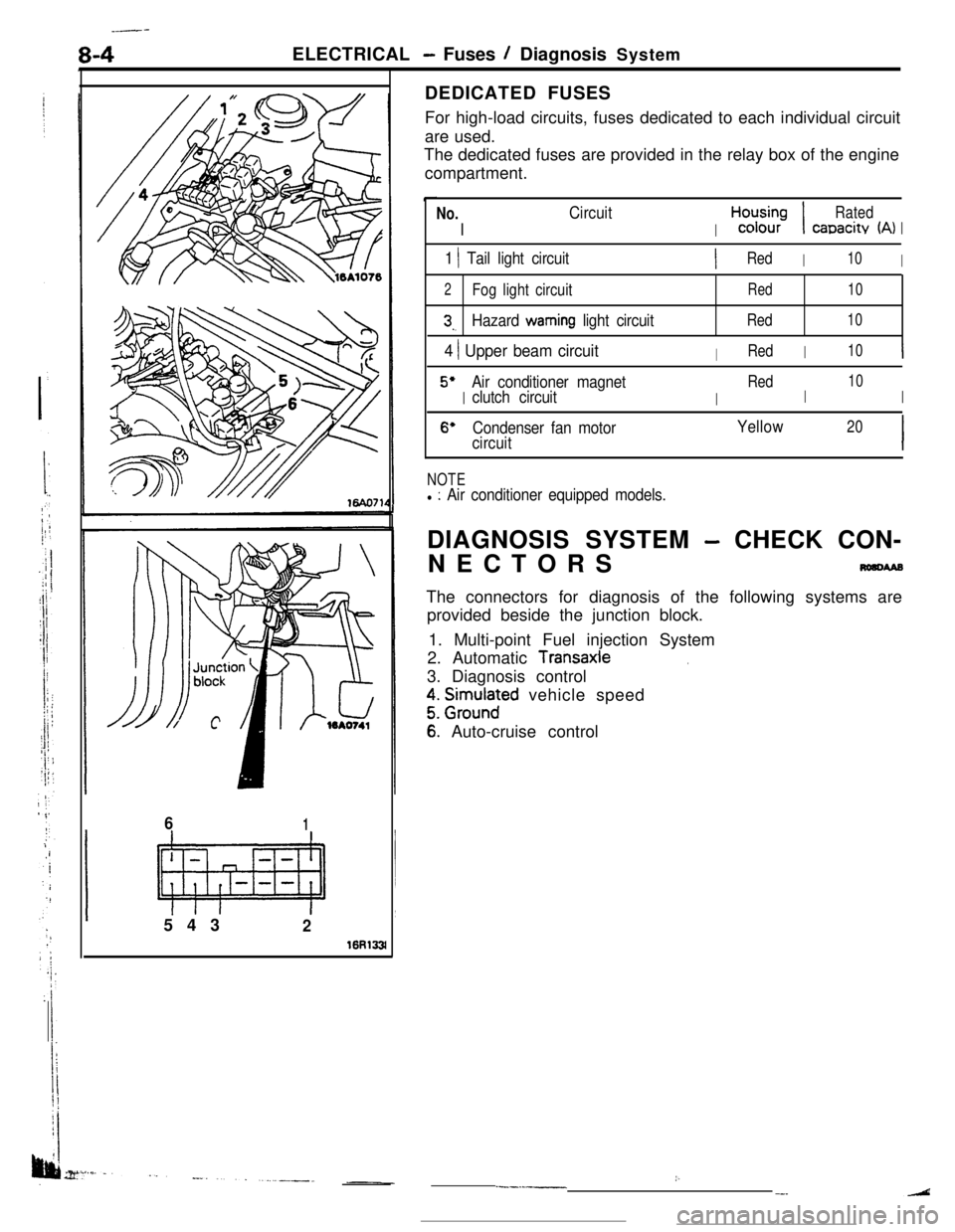
16R133lDEDICATED FUSES
For high-load circuits, fuses dedicated to each individual circuit
are used.
The dedicated fuses are provided in the relay box of the engine
compartment.
No.
I
Circuit
I
H,“d;;-;I
Rated
canacitv (A)I
1 1 Tail light circuitIRedI10I
2Fog light circuitRed10
3,.Hazard warning light circuitRed10
4 ) Upper beam circuitIRedI10I
5’
I
Air conditioner magnet
I
Red
I
10
clutch circuitI
6’Condenser fan motorYellow20
circuitI
NOTEl : Air conditioner equipped models.DIAGNOSIS SYSTEM
- CHECK CON-
NECTORS
nmcwaBThe connectors for diagnosis of the following systems are
provided beside the junction block.
1. Multi-point Fuel injection System
2. Automatic
Transaxle.3. Diagnosis control
z. grm.rlnaFd vehicle speed
6: Auto-cruise control
:..--.-__-.
Page 57 of 391
3i
ELECTRICAL - Junction Block8-5JUNCTION
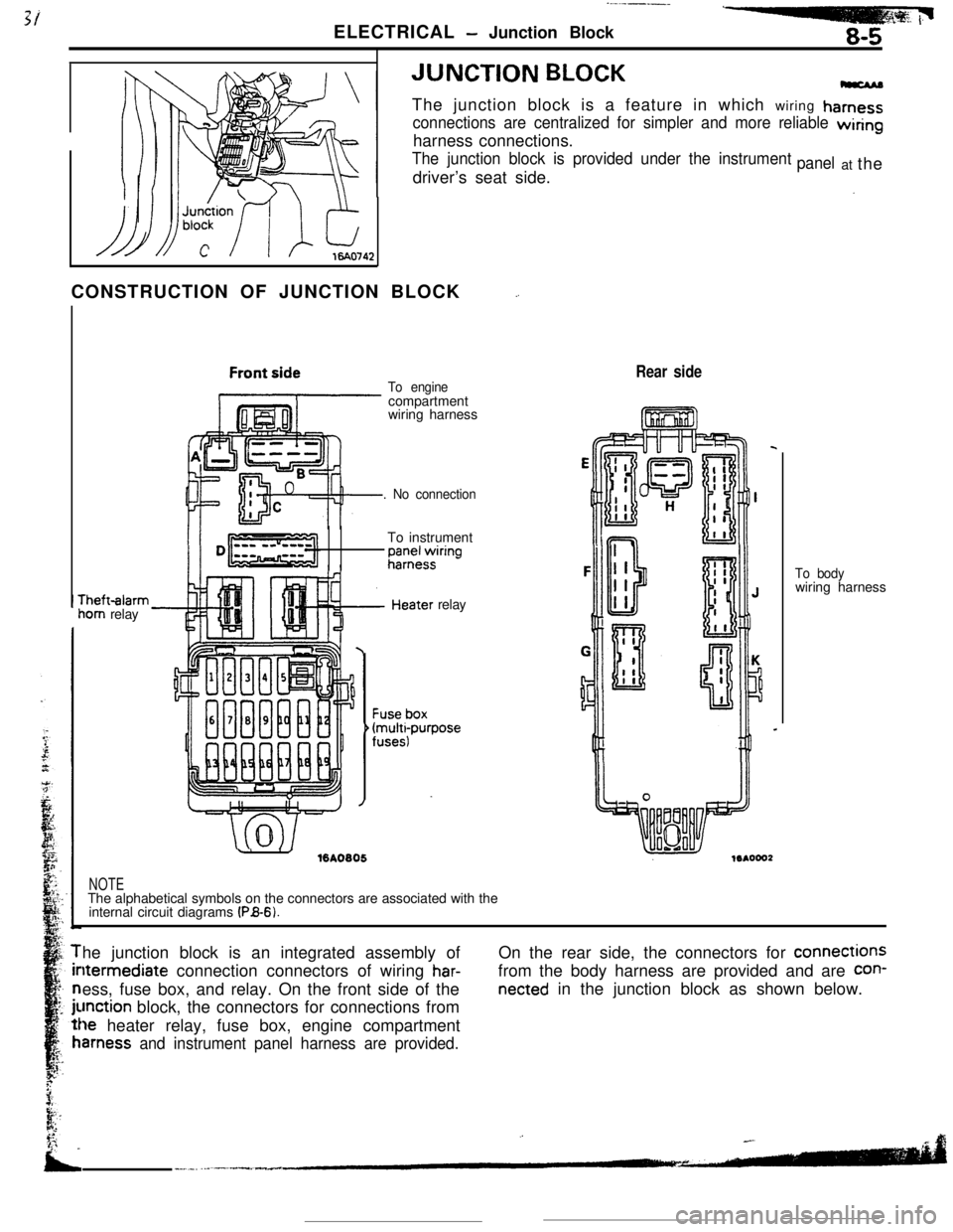
BLOCKThe junction block is a feature in which wiring
hamess
connections are centralized for simpler and more reliable wiringharness connections.
The junction block is provided under the instrumentdriver’s seat side.panelat the
CONSTRUCTION OF JUNCTION BLOCK
_.rheft-alarm
iom relay
To enginecompartment
wiring harness
. No connectionTo instrument
;;;+$ring
.’ ./%A0805relay
Rear side
NOTEThe alphabetical symbols on the connectors are associated with the
internal circuit diagrams
(PB-6).To bodywiring harness
he junction block is an integrated assembly ofltermediate connection connectors of wiring
har-ess, fuse box, and relay. On the front side of the
unction block, the connectors for connections from
le heater relay, fuse box, engine compartment
amess and instrument panel harness are provided.On the rear side, the connectors for connections
from the body harness are provided and are
con-
netted in the junction block as shown below.
Page 74 of 391
8-22ELECTRICAL - Lighting--Ignition ON
switch OFF
prDoor ON
switch OFF
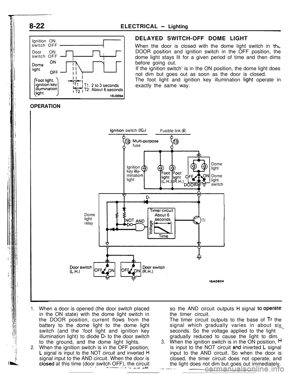
IDELAYED SWITCH-OFF DOME LIGHT
When the door is closed with the dome light switch in
thtDOOR position and ignition switch in the OFF position, the
dome light stays lit for a given period of time and then dims
before going out.
If the ignition switch’ is in the ON position, the dome light does
not dim but goes out as soon as the door is closed.
The foot light and ignition key illumination light operate in
exactly the same way.
16UOO94OPERATIONIgnition switch
(G)Fusible link a
Domelight
relay
9 Mutti-purpose
fuse
%69Ignition
key illu-
minatio
light
Domelight
Domelight
switch
Tr
;:16AO604
1.When a door is opened (the door switch placed
in the ON state) with the dome light switch in
the DOOR position, current flows from the
battery to the dome light to the dome light
switch (and the ‘foot light and ignition key
illumination light) to diode
DI to the door switch
to the ground, and the dome light lights.
2.When the ignition switch is in the OFF position,
L signal is input to the NOT circuit and inverted Hsignal input to the AND circuit. When the door is
-closed at this time (door switch OFF), the circuit
. .----es :- _.a -&Aso the AND circuit outputs
H signal to operate
the timer circuit.
The timer circuit outputs to the base of
Tr the
signal which gradually varies in about six
seconds. So the voltage applied to the light
-gradually reduced to cause the light to dim.
3.When the ignition switch is in the ON position,His input to the NOT circuit
ahd inverted L signal
input to the AND circuit. So when the door is
closed, the timer circuit does not operate, and
the light does not dim but goes out immediately.
_- .-._. ._-__._
Page 338 of 391
BODY - Central Door Locks23-21
IBattery
1IJDoor lock 4Door lockactuator t(left side)actuator
(right side) -Battery
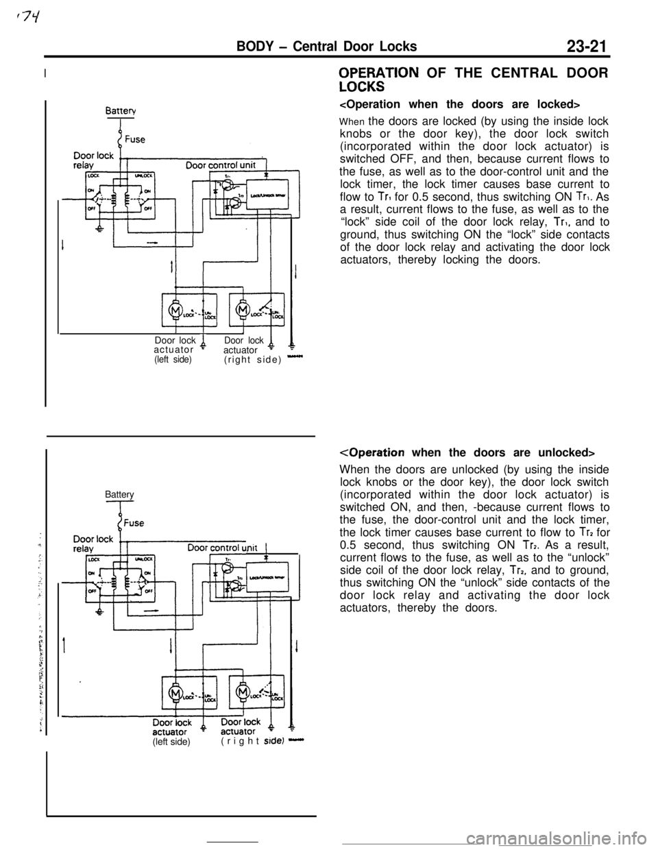
Init !,WF%;$TlON OF THE CENTRAL DOOR
When the doors are locked (by using the inside lock
knobs or the door key), the door lock switch
(incorporated within the door lock actuator) is
switched OFF, and then, because current flows to
the fuse, as well as to the door-control unit and the
lock timer, the lock timer causes base current to
flow to
TrI for 0.5 second, thus switching ON Tr,. As
a result, current flows to the fuse, as well as to the
“lock” side coil of the door lock relay,
Tr,, and to
ground, thus switching ON the “lock” side contacts
of the door lock relay and activating the door lock
actuators, thereby locking the doors.
When the doors are unlocked (by using the inside
lock knobs or the door key), the door lock switch
(incorporated within the door lock actuator) is
switched ON, and then, -because current flows to
the fuse, the door-control unit and the lock timer,
the lock timer causes base current to flow to
Tr? for
0.5 second, thus switching ON
Tr7. As a result,
current flows to the fuse, as well as to the “unlock”
side coil of the door lock relay,
Trp, and to ground,
thus switching ON the “unlock” side contacts of the
door lock relay and activating the door lock
actuators, thereby the doors.
(left side)(right
side) -
Page 339 of 391
23-22BODY - Power Windows
POWER WINDOWS
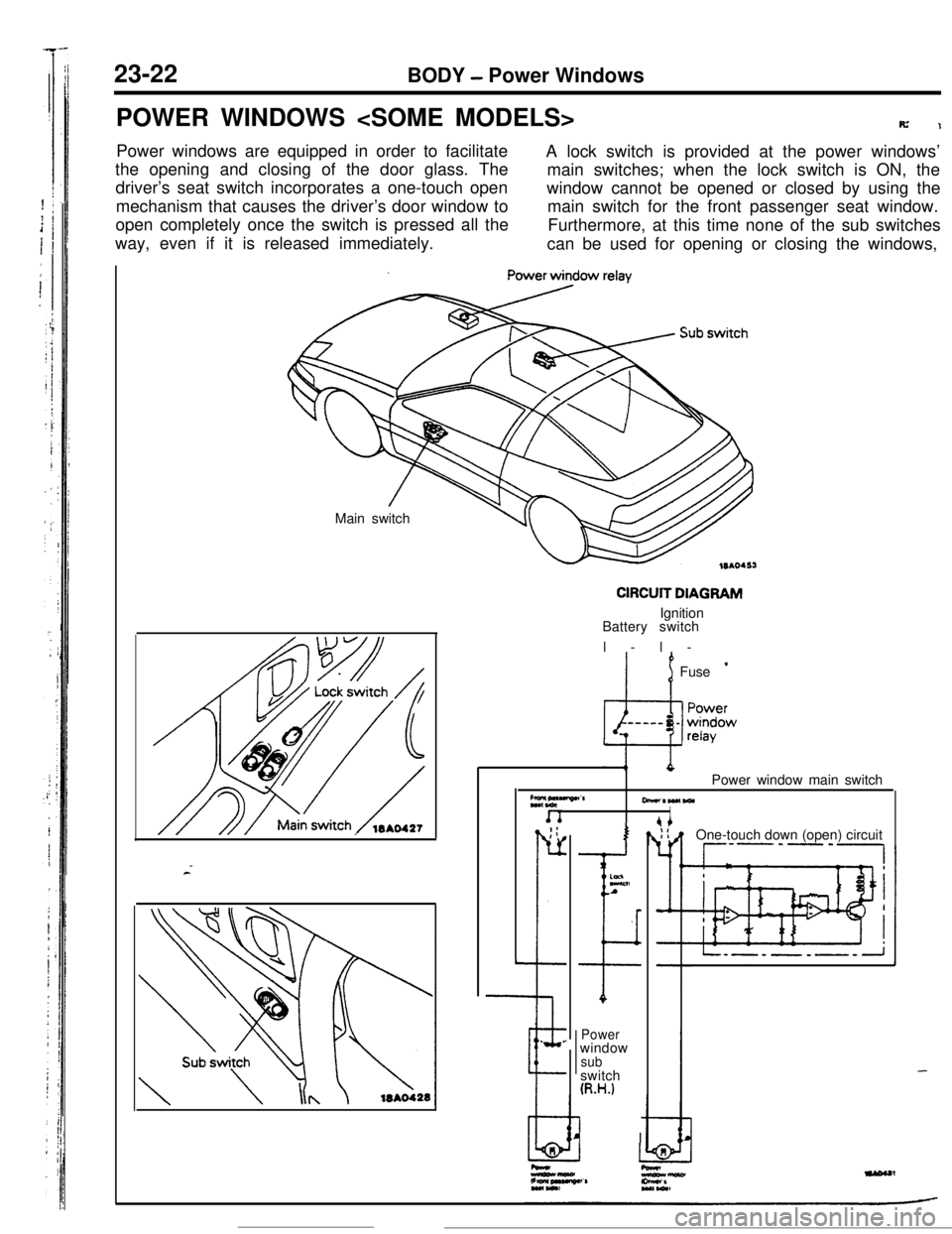
R’1Power windows are equipped in order to facilitate
A lock switch is provided at the power windows’
the opening and closing of the door glass. The
main switches; when the lock switch is ON, the
driver’s seat switch incorporates a one-touch open
mechanism that causes the driver’s door window towindow cannot be opened or closed by using the
main switch for the front passenger seat window.
open completely once the switch is pressed all the
way, even if it is released immediately.Furthermore, at this time none of the sub switches
can be used for opening or closing the windows,
Main switch
CIRCUIT DIAGRAMIgnition
Battery switch
l-l-
’ 1Fuse ’
Z*,“““”CrPower window main switch
-*W(WlI. _;:
r-
L
--e.
.
I
ELnA
I
Powerwindow
subswitch
(R.H.)
I IOne-touch down (open) circuit
--P’-‘-,
-
Page 355 of 391
23-38BODY - Seat Belts
Motor (L.H.,
R.H.)
Manual Procedure
Door Latch Switch (L.H., R.H.)
7
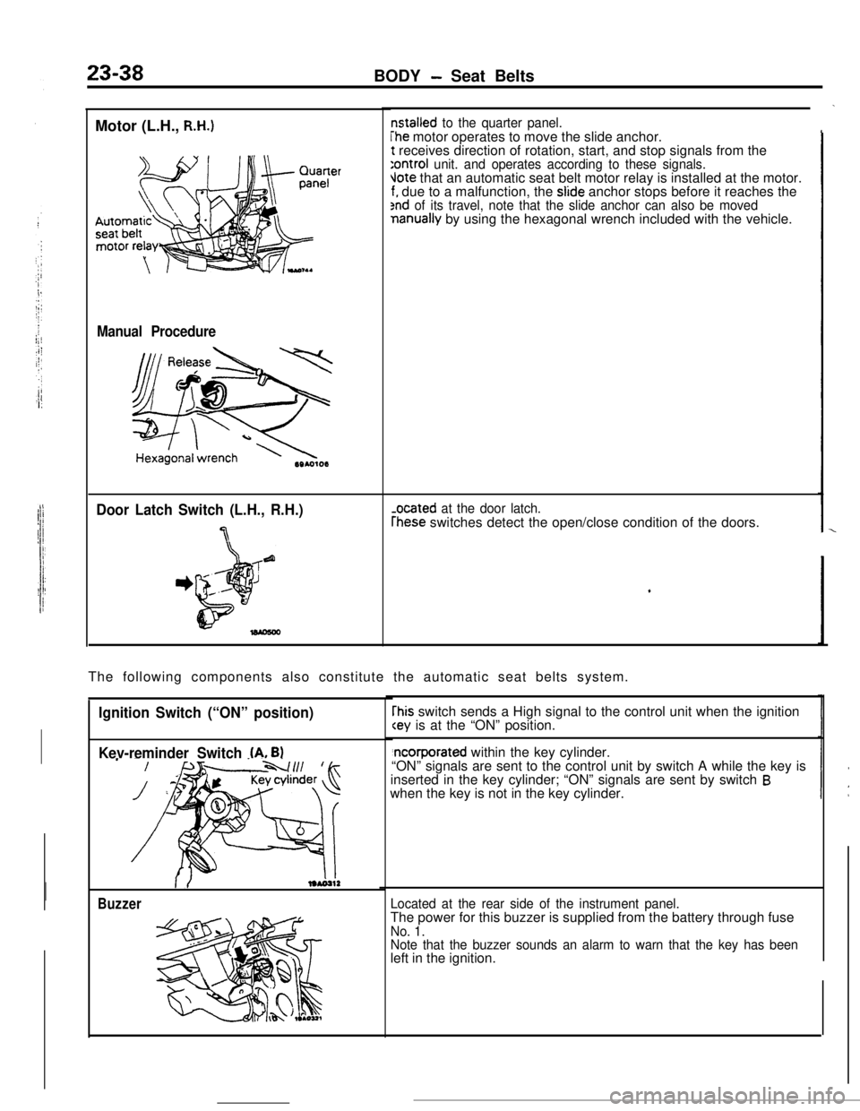
nstalled to the quarter panel.
The motor operates to move the slide anchor.t receives direction of rotation, start, and stop signals from the
:ontroi unit. and operates according to these signals.Jote that an automatic seat belt motor relay is installed at the motor.f. due to a malfunction, the slide anchor stops before it reaches the2nd of its travel, note that the slide anchor can also be movednanually by using the hexagonal wrench included with the vehicle.
-ocated at the door latch.
rhese switches detect the open/close condition of the doors.
The following components also constitute the automatic seat belts system.
Ignition Switch (“ON” position)
Kev-reminder Switch
(A. B)
Buzzer
rhis switch sends a High signal to the control unit when the ignition
“ON” signals are sent to the control unit by switch A while the key is
inserted in the key cylinder; “ON” signals are sent by switch
Bwhen the key is not in the key cylinder.
Located at the rear side of the instrument panel.The power for this buzzer is supplied from the battery through fuse
No. 1.
Note that the buzzer sounds an alarm to warn that the key has beenleft in the ignition.
Page 371 of 391
-.-- ----_-
24-8HEATERS AND AIR CONDITIONING - Compressor
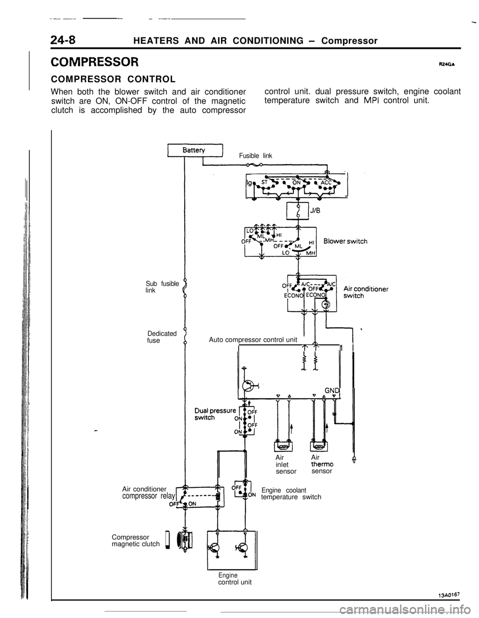
COMPRESSORR24GbCOMPRESSOR CONTROL
When both the blower switch and air conditioner
switch are ON, ON-OFF control of the magnetic
clutch is accomplished by the auto compressorcontrol unit. dual pressure switch, engine coolant
temperature switch and
MPI control unit.
Sub fusible
link
Dedicatedfuse
Air conditioner
compressor relayrOFfCompressor
magnetic clutch
q l
Fusible link
lgnitionsyhWqb 1Auto compressor control unit
ITT1 I
0 bIAirAir
inlettherm0
4sensorsensor
Engine coolanttemperature switch
Enginecontrol unit13A0167
Page 372 of 391
19/---..-_HEATERS AND AIR CONDITIONING
- Idle Speed Control24-9
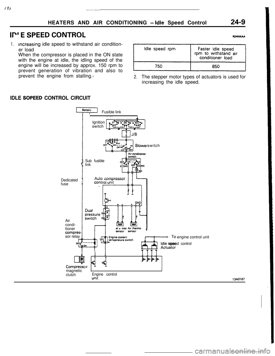
Ii” E SPEED CONTROL
1.increasing idle speed to withstand air condition-
er load
When the compressor is placed in the ON state
with the engine at idle, the idling speed of the
engine will be increased by approx. 150 rpm to
prevent generation of vibration and also to
prevent the engine from stalling.-
2.The stepper motor types of actuators is used for
increasing the idle speed.
IDLE SOPEED CONTROL CIRCUITFusible link
Dedicatedfuse
Air
condi-tioner
compressor relay
I-gcfc
Lll
Compre:Ignition
switch
Sub fusible
linkswitch
Auto compressor
As
mlef kr Ihemo
Ax;,: engine control unit
Idle speed control
Y *e:Q
1
$4.1111.Pk+F)rmagneticIJ
clutchEngine controlunit13AO167