length MITSUBISHI ECLIPSE 1990 Service Manual
[x] Cancel search | Manufacturer: MITSUBISHI, Model Year: 1990, Model line: ECLIPSE, Model: MITSUBISHI ECLIPSE 1990Pages: 391, PDF Size: 15.27 MB
Page 8 of 391
o-4GENERAL - Technical Features
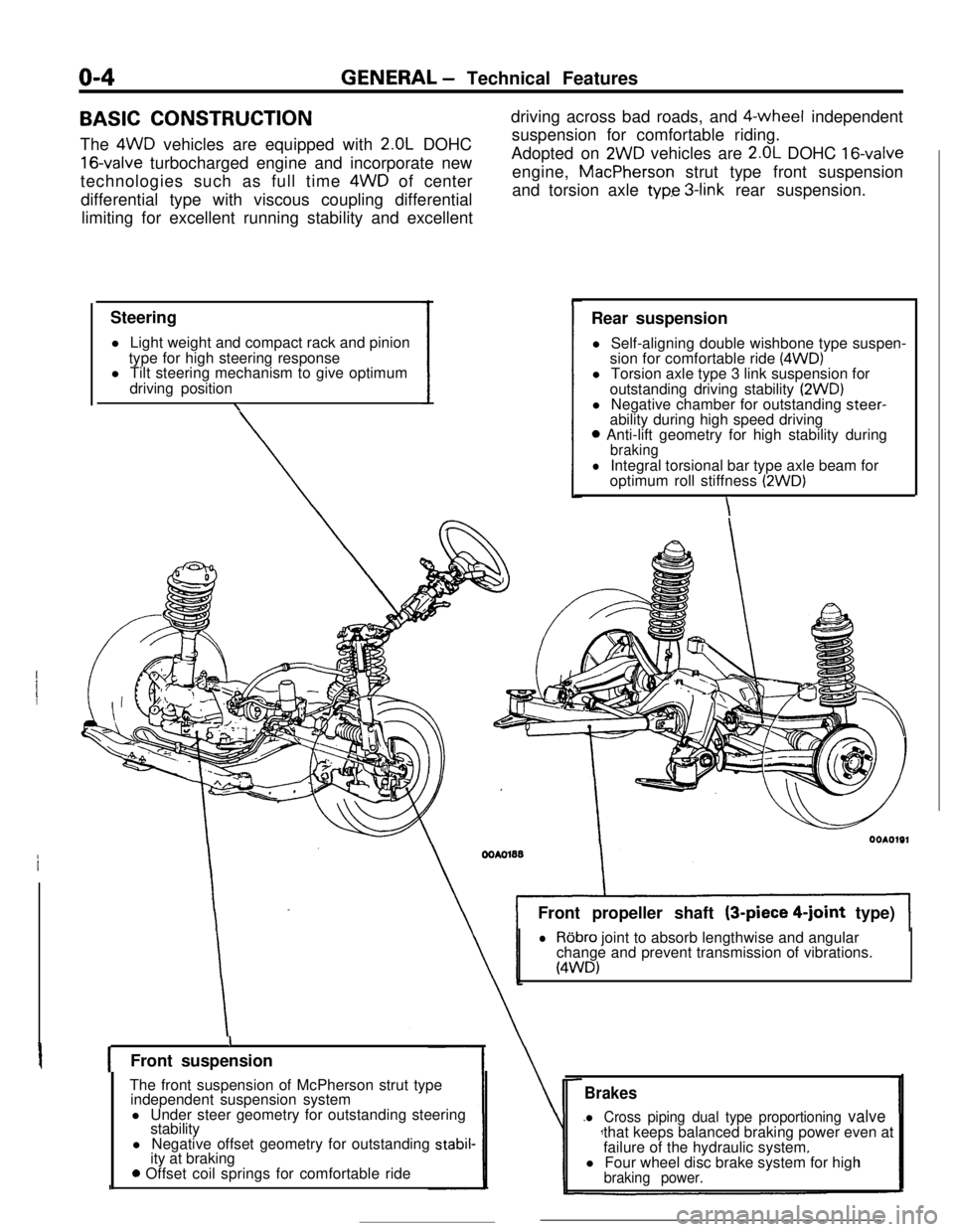
BASIC CONSTRUCTION
The 4WD vehicles are equipped with
2.OL DOHC
16-valve turbocharged engine and incorporate new
technologies such as full time 4WD of center
differential type with viscous coupling differential
limiting for excellent running stability and excellent
Steering
l Light weight and compact rack and pinion
type for high steering response
l Tilt steering mechanism to give optimum
driving position
\driving across bad roads, and $-wheel independent
suspension for comfortable riding.
Adopted on
2WD vehicles are 2.OL DOHC 16-valveengine, MacPherson strut type front suspension
and torsion axle
typ.e 3-link rear suspension.
Rear suspension
l Self-aligning double wishbone type suspen-
sion for comfortable ride
(4WD)l Torsion axle type 3 link suspension for
outstanding driving stability
(2WD)l Negative chamber for outstanding steer-
ability during high speed driving
0 Anti-lift geometry for high stability duringbraking
lIntegral torsional bar type axle beam for
optimum roll stiffness (2WD)
\Front propeller shaft (3-piece
4-joint type)
lRobro joint to absorb lengthwise and angular
change and prevent transmission of vibrations.
(4WD)
IFront suspension
The front suspension of McPherson strut type
independent suspension system
l Under steer geometry for outstanding steering
stability
l Negative offset geometry for outstanding
stabil-ity at braking
0 Offset coil springs for comfortable ride
Brakes
l Cross piping dual type proportioning valvethat keeps balanced braking power even at
failure of the hydraulic system.
l Four wheel disc brake system for high
braking power.
Page 17 of 391
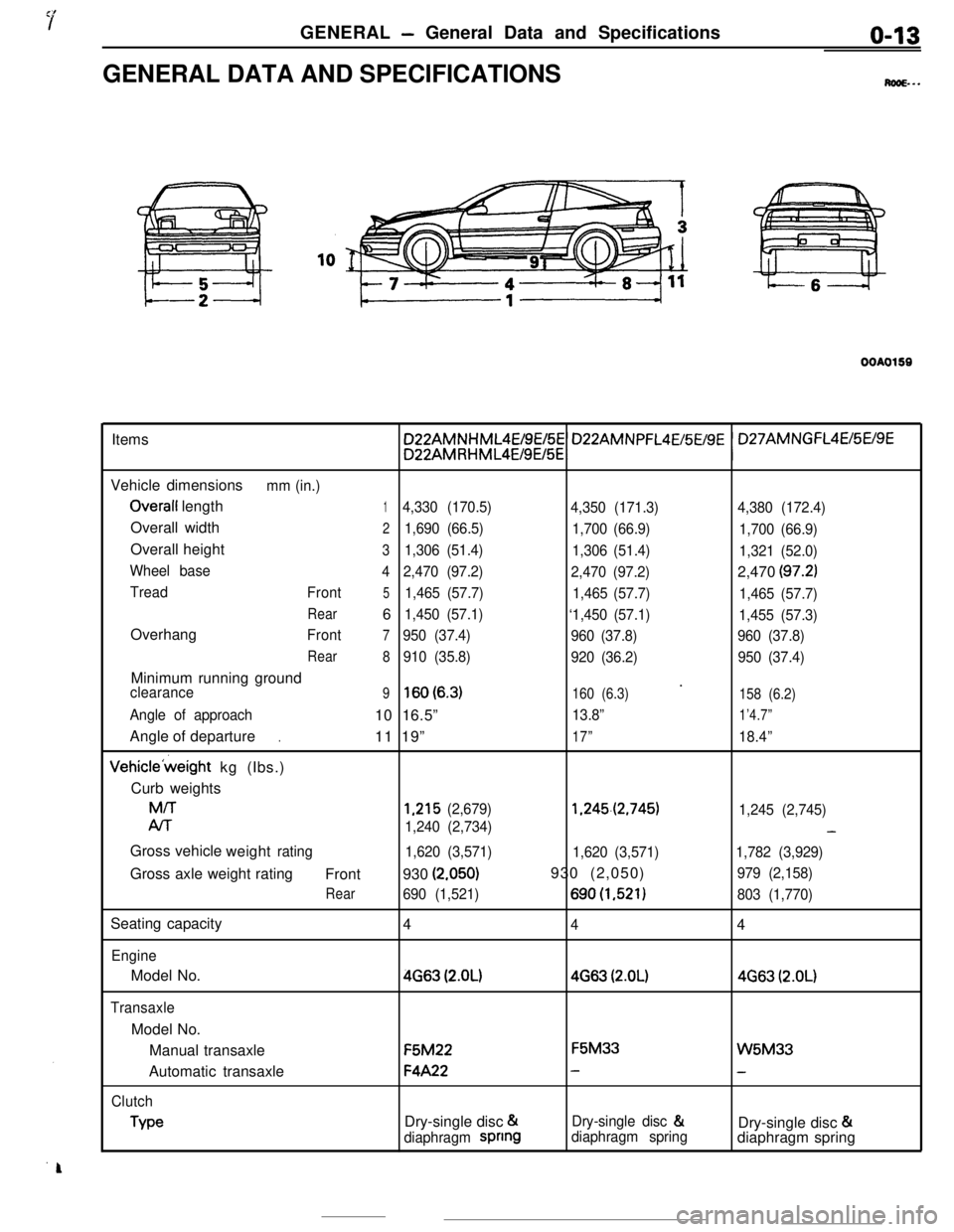
GENERAL - General Data and Specificationso-13GENERAL DATA AND SPECIFICATIONS
M...
OOAO159Items
Vehicle dimensions
mm (in.)
Overall length14,330 (170.5)
4,350 (171.3)4,380 (172.4)Overall width
21,690 (66.5)
1,700 (66.9)
1,700 (66.9)Overall height
31,306 (51.4)
1,306 (51.4)
1,321 (52.0)
Wheel base
42,470 (97.2)
2,470 (97.2)2,470
(97.2)
Tread
Front51,465 (57.7)
1,465 (57.7)
1,465 (57.7)
Rear61,450 (57.1)
‘1,450 (57.1)
1,455 (57.3)Overhang
Front7950 (37.4)
960 (37.8)960 (37.8)
Rear
8910 (35.8)
920 (36.2)950 (37.4)Minimum running ground
’clearance9lsO(6.3)160 (6.3)
158 (6.2)
Angle of approach10 16.5”13.8”1’4.7”Angle of departure
11 19”
17”18.4”.Vehicle’weight kg (Ibs.)
Curb weightsM/T
1,215 (2,679)1.245.(2,745)
1,245 (2,745)
Al-r
1,240 (2,734)-Gross vehicle
weight
rating
1,620 (3,571)
1,620 (3,571)1,782 (3,929)Gross axle weight rating
Front930
(2.050)930 (2,050)979 (2,158)
Rear690 (1,521)690(1,521)803 (1,770)Seating capacity
4
44
EngineModel No.
4663 (2.OL)4663 (2.OL)4663 (2.OL)
TransaxleModel No.
Manual transaxleF5M22F5M33
W5M33Automatic transaxle
F4A22--
Clutch
TypeDry-single disc &Dry-single disc &
Dry-single disc &
diaphragm spnngdiaphragm springdiaphragm spring
Page 21 of 391
FRONT SUSPENSION - General Information2-3
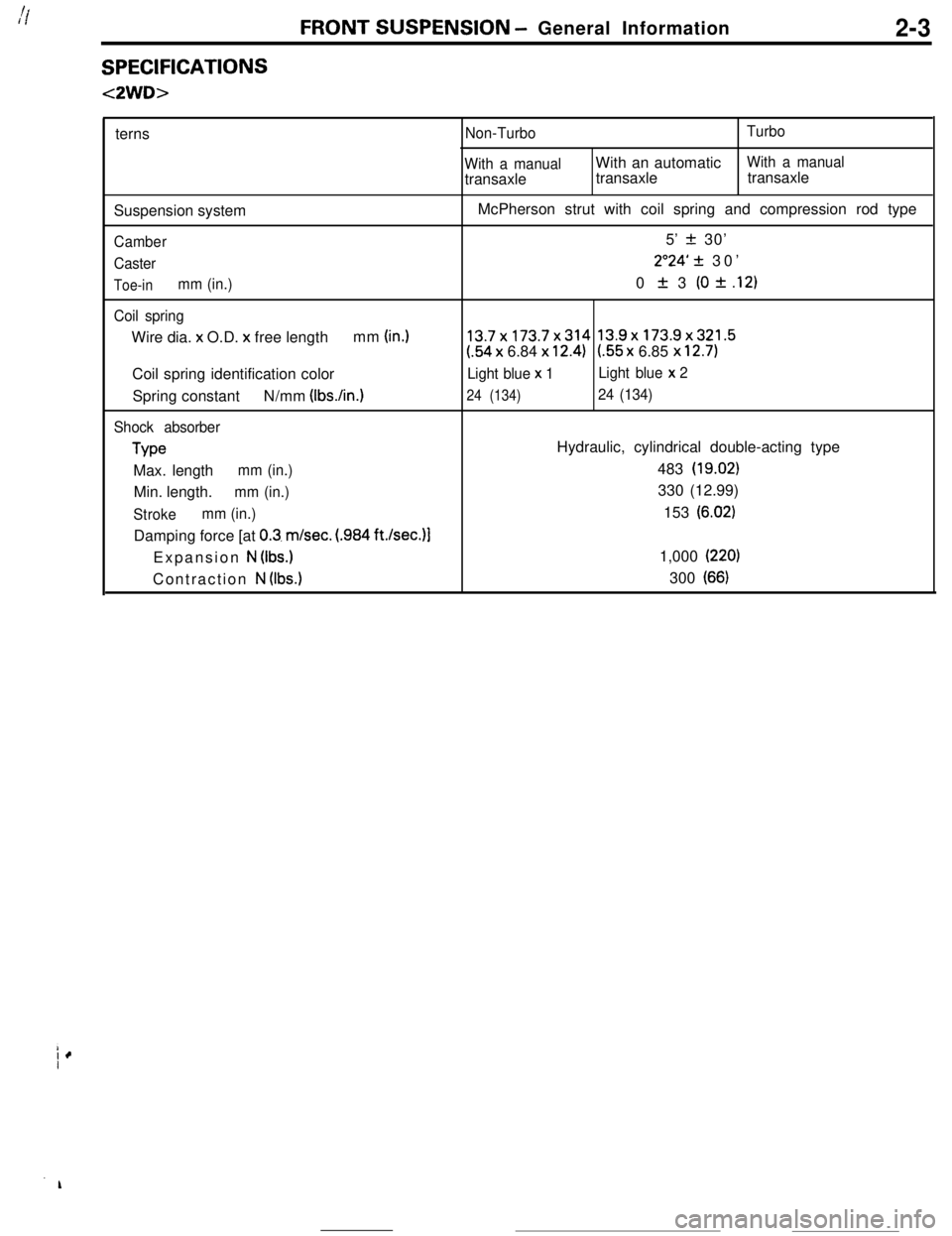
SPECIFICATIONS
<2WD>terns
Suspension system
Camber
Caster
Toe-inmm (in.)
Coil springWire dia. x O.D.
x free lengthmm (in.)Coil spring identification color
Spring constantN/mm (IbsAn.)
Shock absorber
TypeMax. length
mm (in.)Min. length.
mm (in.)
Strokemm (in.)Damping force [at
0.3. m/set. (.984 ft./sec.)l
Expansion
N (Ibs.)Contraction
N (Ibs.)
Non-TurboTurbo
With a manualWith an automatic
With a manualtransaxletransaxletransaxle
McPherson strut with coil spring and compression rod type
5’
z!z 30’
2”24’ 31 30’
0
It 3 (0 * .12)
13.7x173.7x314 13.9x173.9x321.5
(.54 x 6.84 x 12.4)l.55 x 6.85 x 12.7)
Light blue x 1Light blue x 2
24 (134)24 (134)Hydraulic, cylindrical double-acting type
483
(19.02)330 (12.99)
153
(6.02)1,000
(220)300
(66)
Page 22 of 391
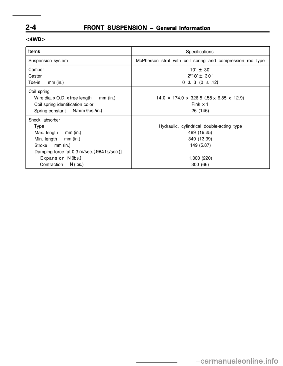
FRONT SUSPENSION - General Information
c4WD>Items
Suspension system
CamberCaster
Toe-inmm (in.)
Coil springWire dia. x O.D. x free length
mm (in.)Coil spring identification color
Spring constantN/mm
(Ibs./in.)
Shock absorber
TypeMax. length
mm (in.)Min. length
mm (in.)
Strokemm (in.)Damping force [at 0.3
m/set. (.984 ft./set.)]Expansion
N (Ibs.)Contraction
N (Ibs.)Specifications
McPherson strut with coil spring and compression rod type
10’
+- 30’
2”18’ + 30’
0
zk 3 (0 f .l2)14.0 x 174.0
x 326.5 (.55 x 6.85 x 12.9)
Pink x 1
26 (146)
Hydraulic, cylindrical double-acting type
489 (19.25)
340 (13.39)
149 (5.87)
1,000 (220)
300 (66)
Page 30 of 391
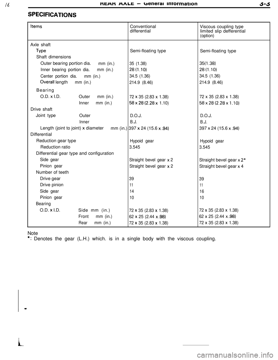
SPECIFICATIONSMEHM
nnlL -ueneral mrormationJ-JItemsConventional
differentialViscous coupling type
limited slip defferential
(option)Axle shaft
TypeSemi-floating type
Shaft dimensions
Outer bearing portion dia.
mm (in.)35 (1.38)
Inner bearing portion dia.mm (in.)28t1.10)
Center portion dia.
mm (in.)34.5 (1.36)
Overall lengthmm (in.)
214.9 (8.46)Bearing
O.D. x I.D.
Outer
mm (in.)
72 x 35 (2.83 x 1.38)
Innermm (in.)
58x28(2.28x 1.10)Drive shaft
Joint type
Outer
D.O.J.
Inner
B.J.Length (joint to joint)
x diameter
mm (in.) 397 x 24 (15.6 x .94)Differential
Reduction gear type
Hypoid gearReduction ratio
3.545Differential gear type and configuration
Side gear
Straight bevel gear x 2
Pinion gear
Straight bevel gear x
2Number of teeth
Drive gear
39Drive pinion
11
Side gear14
Pinion gear10
BearingO.D.
x I.D.
Side mm (in.)72 x 35 (2.83 x 1.38)
Frontmm (in.)
62 x
25 (2.44 x .98)
Rearmm (in.)
72 x 35 (2.83 x 1.38)NoteSemi-floating type
35f1.38)28t1.10)
34.5 (1.36)
214.9 (8.46)
72
x 35 (2.83 x 1.38)
58x28(2.28x1.10)
D.O.J.
B.J.397 x 24 (15.6 x
.94)
Hypoid gear
3.545Straight bevel gear x
2”Straight bevel gear x 4
39
11
16
10
72 x 35 (2.83 x 1.38)
62
x 25 (2.44 x .98)
72 x 35 (2.83 x 1.38)
*: Denotes the gear (L.H.) which. is in a single body with the viscous coupling.
i
Page 31 of 391
3-4REAR AXLE - Axle Shaft / Drive Shaft
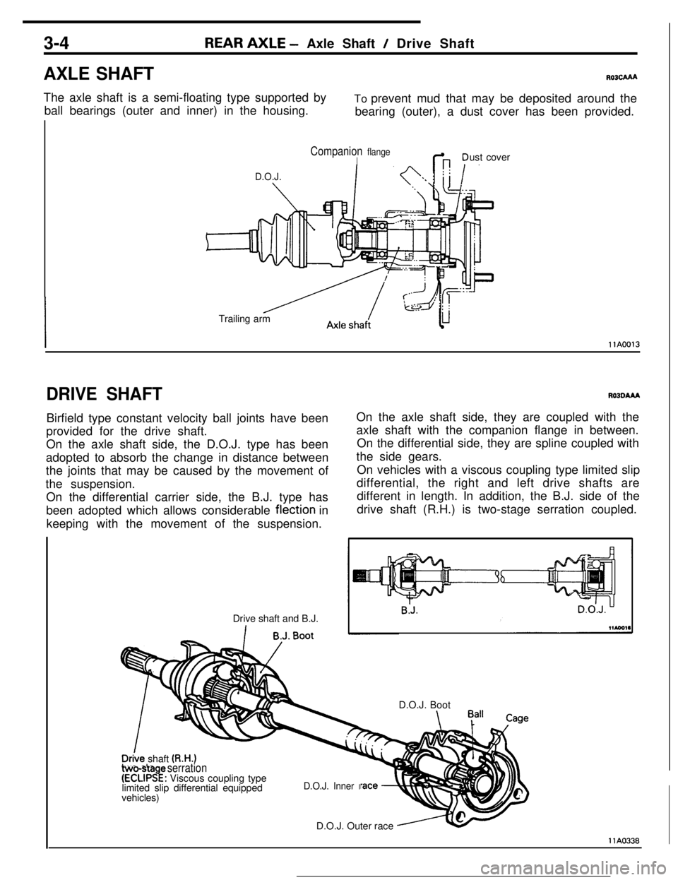
AXLE SHAFT
R03cAAAThe axle shaft is a semi-floating type supported by
ball bearings (outer and inner) in the housing.To prevent mud that may be deposited around the
bearing (outer), a dust cover has been provided.
D.O.J.
Companion flangeIG ?ust cover
Trailing arm
IllA0013
DRIVE SHAFTBirfield type constant velocity ball joints have been
provided for the drive shaft.
On the axle shaft side, the D.O.J. type has been
adopted to absorb the change in distance between
the joints that may be caused by the movement of
the suspension.
On the differential carrier side, the B.J. type has
been adopted which allows considerable flection in
keeping with the movement of the suspension.
Drive shaft and B.J.RO3OAAAOn the axle shaft side, they are coupled with the
axle shaft with the companion flange in between.
On the differential side, they are spline coupled with
the side gears.
On vehicles with a viscous coupling type limited slip
differential, the right and left drive shafts are
different in length. In addition, the B.J. side of the
drive shaft (R.H.) is two-stage serration coupled.
D.O.J. Boot
_vehicles)
D.O.J. Outer race
D&e shaft (R.H.)two-sta e serration(ECLIPS!: Viscous coupling type
limited slip differential equipped
D.O.J. Inner I
llA0338
Page 192 of 391
PROPELLER SHAFT -General Information / Liibro Joint16-3
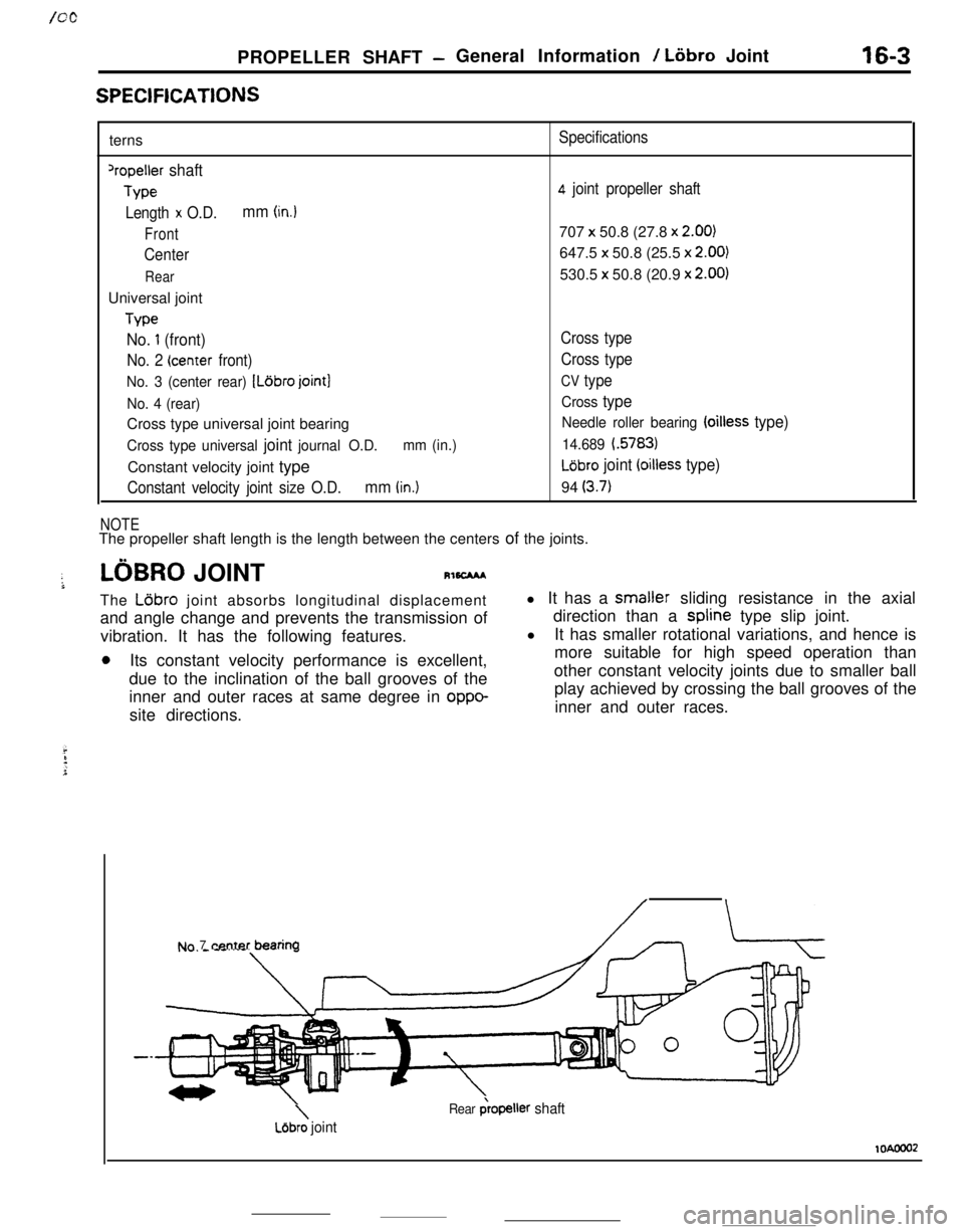
SPEClFlCATlONSterns
‘repeller shaft
Type
Length
x O.D.mm (in.)
Front
Center
RearUniversal joint
Type
No. 1 (front)
No. 2 (center front)
No. 3 (center rear) [Ldbro joint]
No. 4 (rear)Cross type universal joint bearing
Cross type universal joint journal O.D.mm (in.)Constant velocity joint type
Constant velocity joint size O.D.mm (in.)
NOTE
Specifications
4 joint propeller shaft707
x 50.8 (27.8 x 2.00)647.5 x 50.8 (25.5 x
2.00)530.5 x 50.8 (20.9 x
2.00)
Cross type
Cross type
CV type
Cross type
Needle roller bearing (oilless type)
14.689 i.5783)
LGbro joint (oilless type)94
(3.7)The propeller shaft length is the length between the centers of the joints.
LOBRO JOINTRl6CMAThe
L6bro joint absorbs longitudinal displacement
and angle change and prevents the transmission of
vibration. It has the following features.
0Its constant velocity performance is excellent,
due to the inclination of the ball grooves of the
inner and outer races at same degree in
oppo-site directions.l It has a smaller sliding resistance in the axial
direction than a spline type slip joint.
l
It has smaller rotational variations, and hence is
more suitable for high speed operation than
other constant velocity joints due to smaller ball
play achieved by crossing the ball grooves of the
inner and outer races.
Nn 7 center bearina
\Lejbro joint
Rear &opeller shaft
lOAooo2
Page 202 of 391
_ -. ..__ .-
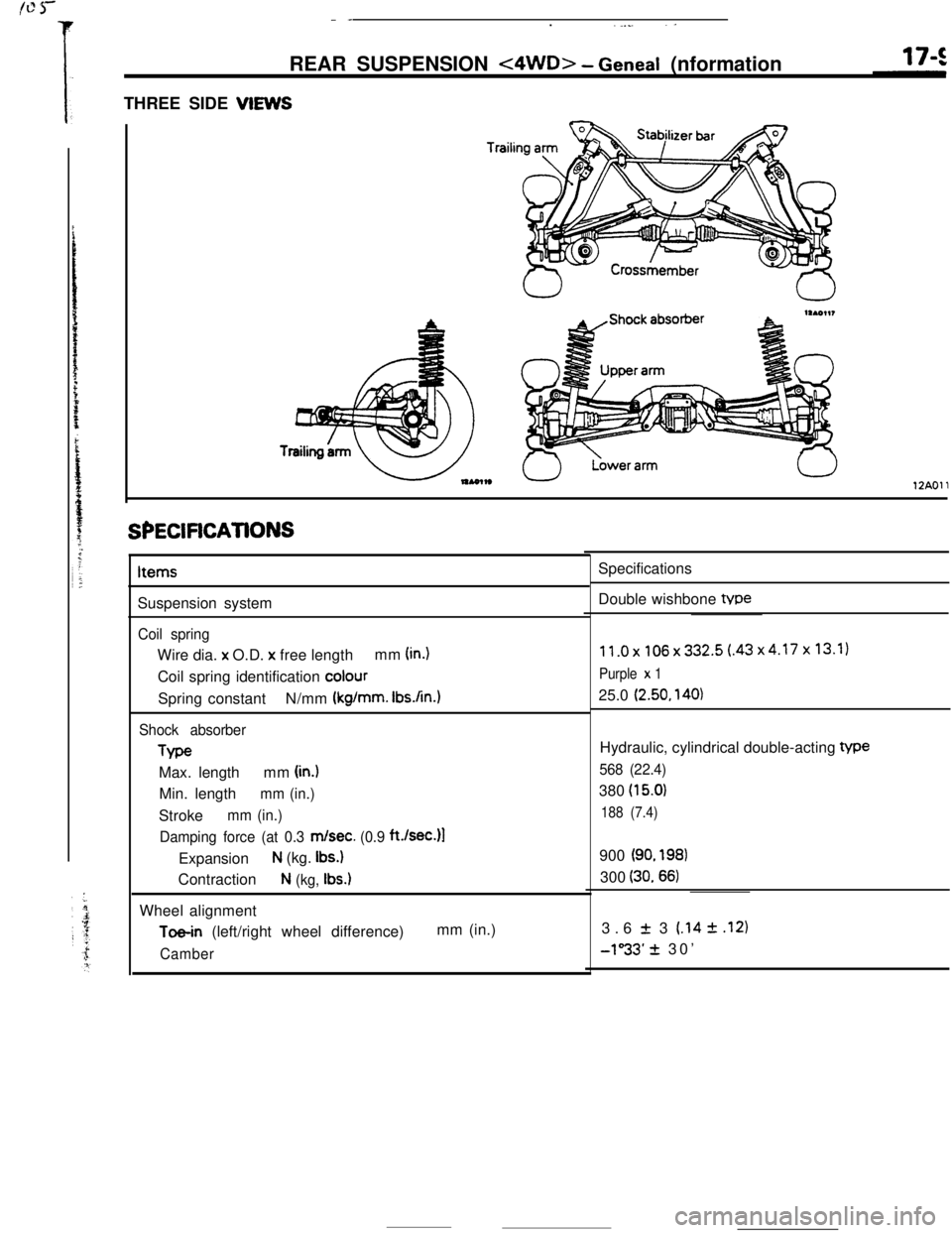
REAR SUSPENSION
<4WD> - Geneal (nformation
THREE SIDE VIEWS
Trailil
12AOll
SPECiFiCATiONSItems
Suspension system
Coil springWire dia. x O.D.
x free lengthmm (in.)Coil spring identification
colourSpring constantN/mm
(kg/mm. Ibs.An.1
Shock absorberType
Max. lengthmm
(in.)Min. length
mm (in.)Stroke
mm (in.)
Damping force (at 0.3
m/set. (0.9 ft./sec.)l
Expansion
N (kg. Ibs.)Contraction
N (kg, Ibs.)Wheel alignment
Toe-in (left/right wheel difference)mm (in.)
CamberSpecifications
Double wishbone tvpe
11.0x106x332.5(.43x4.17x13.1)
Purple x 125.0
(2.50, 140)Hydraulic, cylindrical double-acting
We
568 (22.4)380
(15.0)
188 (7.4)900
(90. 198)300
(30.66)3.6
f 3 (.14 2 .I21
-1”33’ + 30’
Page 259 of 391
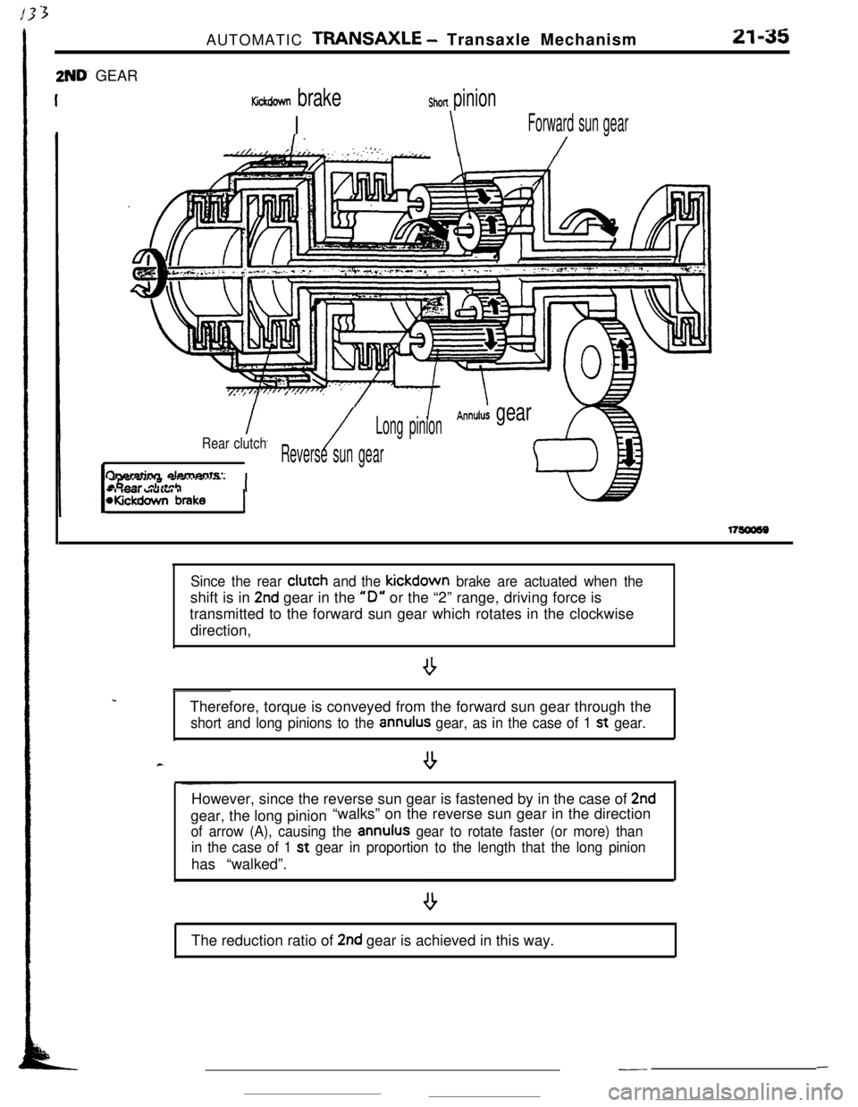
2ND’ GEARAUTOMATIC
TRANSAXLE - Transaxle Mechanism21-35
Kickdown brake
I
Shon pinion
\Forward sun gear
1.//LT.//. , ,’ .‘,,i.:,;:.:‘.,.‘,\/
/
Annulus gearLong pinion
Rear clutch/Reverse sun gear
fharatinn damants:
-, IWI WUIUI IWickdown brakeI
.
c
Since the rear clutch and the kickdown brake are actuated when theshift is in
2nd gear in the “0” or the “2” range, driving force is
transmitted to the forward sun gear which rotates in the clockwise
direction,
Therefore, torque is conveyed from the forward sun gear through the
short and long pinions to the annulus gear, as in the case of 1 st gear.
--However, since the reverse sun gear is fastened by in the case of
2ndgear, the long pinion“walks” on the reverse sun gear in the direction
of arrow (A), causing the annulus gear to rotate faster (or more) than
in the case of 1 st
gear in proportion to the length that the long pinionhas “walked”.
The reduction ratio of
2nd gear is achieved in this way.
---
Page 354 of 391
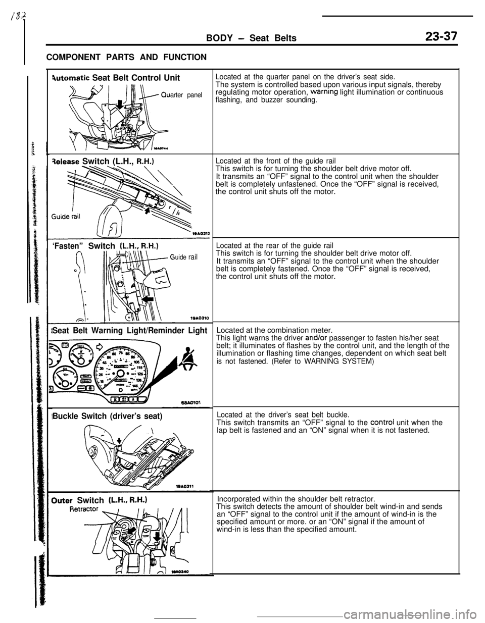
BODY - Seat Belts23-37COMPONENT PARTS AND FUNCTION
4utomatic Seat Belt Control Unit
arter panel
qelease Switch (L.H., R.H.)
‘Fasten”Switch (L.H., R.H.)
uide rail
1SAO310
Seat Belt Warning Light/Reminder Light
Buckle Switch (driver’s seat)
Outer Switch (LH., R.H.)
Located at the quarter panel on the driver’s seat side.The system is controlled based upon various input signals, thereby
regulating motor operation,
warnrng light illumination or continuousflashing, and buzzer sounding.
Located at the front of the guide railThis switch is for turning the shoulder belt drive motor off.
It transmits an “OFF” signal to the control unit when the shoulder
belt is completely unfastened. Once the “OFF” signal is received,
the control unit shuts off the motor.
Located at the rear of the guide railThis switch is for turning the shoulder belt drive motor off.
It transmits an “OFF” signal to the control unit when the shoulder
belt is completely fastened. Once the “OFF” signal is received,
the control unit shuts off the motor.
Located at the combination meter.
This light warns the driver
and/or passenger to fasten his/her seat
belt; it illuminates of flashes by the control unit, and the length of the
illumination or flashing time changes, dependent on which seat belt
is not fastened. (Refer to WARNING SYSTEM)
Located at the driver’s seat belt buckle.This switch transmits an “OFF” signal to the
control unit when the
lap belt is fastened and an “ON” signal when it is not fastened.
Incorporated within the shoulder belt retractor.
This switch detects the amount of shoulder belt wind-in and sends
an “OFF” signal to the control unit if the amount of wind-in is the
specified amount or more. or an “ON” signal if the amount of
wind-in is less than the specified amount.