brake sensor MITSUBISHI ECLIPSE 1990 Service Manual
[x] Cancel search | Manufacturer: MITSUBISHI, Model Year: 1990, Model line: ECLIPSE, Model: MITSUBISHI ECLIPSE 1990Pages: 391, PDF Size: 15.27 MB
Page 39 of 391

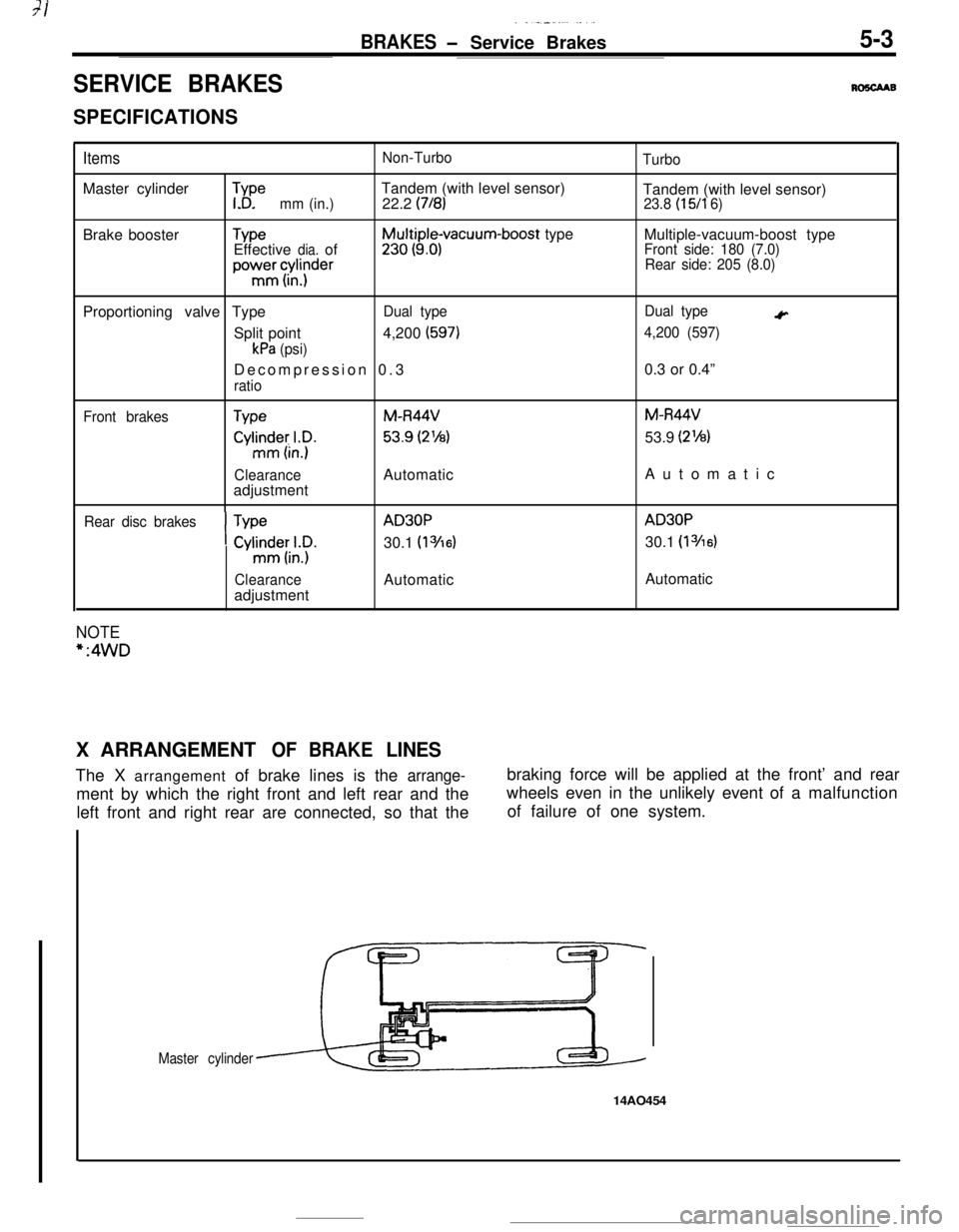
BRAKES - Service Brakes 5-3
$eTandem (with level sensor)
(718)
Brake boosterTYpeEffective dia. of
y3tt$;ivacuum-boost type
powmermc&;der
Proportioning valve Type Dual type
(597)
kPa (psi)
Decompression 0. 3
(15/l 6)
Multiple-vacuum-boost type
c
4,200 (597)
TypeM-R44VM-R44V
cyhnxLy.53.9 (2’/8) 53.9 (2%)
Clearance Automatic Automati
c
I
TypeAD30PAD30P
Cyl~itl;.~. 30.1 (13/16) 30.1 (13/16)
Clearance Automatic Automatic
*:4WD
X
ARRANGEMENT OF BRAKE LINES
Page 182 of 391

14-70
-_FUEL SYSTEM
- Auto-cruise Control System
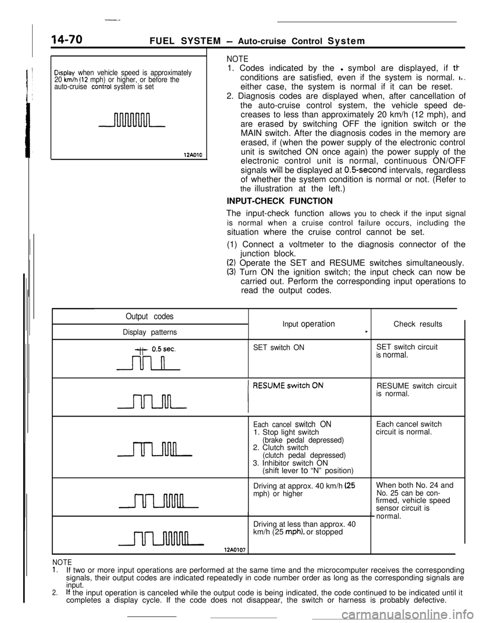
Display when vehicle speed is approximately
20 km/h (12 mph) or higher, or before the
auto-cruise conrrol system is set
12AolO
NOTE1. Codes indicated by thel symbol are displayed, if
tt-conditions are satisfied, even if the system is normal.
I,.either case, the system is normal if it can be reset.
2. Diagnosis codes are displayed when, after cancellation of
the auto-cruise control system, the vehicle speed de-
creases to less than approximately 20 km/h (12 mph), and
are erased by switching OFF the ignition switch or the
MAIN switch. After the diagnosis codes in the memory are
erased, if (when the power supply of the electronic control
unit is switched ON once again) the power supply of the
electronic control unit is normal, continuous ON/OFF
signals will be displayed at
O.&second intervals, regardless
of whether the system condition is normal or not. (Refer to
the illustration at the left.)
INPUT-CHECK FUNCTION
The input-check function allows you to check if the input signal
is normal when a cruise control failure occurs, including the
situation where the cruise control cannot be set.
(1) Connect a voltmeter to the diagnosis connector of the
junction block.
(2) Operate the SET and RESUME switches simultaneously.
(3) Turn ON the ignition switch; the input check can now be
carried out. Perform the corresponding input operations to
read the output codes.
Output codes
Display patternsInput
operationCheck resultst
y- 0.5sec.
n
SET switch ONSET switch circuitis normal.RESUME switch circuit
is normal.
Each cancel switch ON1. Stop light switch
(brake pedal depressed)2. Clutch switch
(clutch pedal depressed)3. Inhibitor switch ON
(shift lever to “N” position)Each cancel switch
circuit is normal.
Driving at approx. 40 km/h
(25mph) or higherWhen both No. 24 andNo. 25 can be con-firmed, vehicle speed
sensor circuit is
normal.Driving at less than approx. 40
km/h (25
mph). or stopped
NOTE1.If two or more input operations are performed at the same time and the microcomputer receives the corresponding
signals, their output codes are indicated repeatedly in code number order as long as the corresponding signals are
2.input.If the input operation is canceled while the output code is being indicated, the code continued to be indicated until it
completes a display cycle. If the code does not disappear, the switch or harness is probably defective.
Page 269 of 391

‘4) Once the operation is step (2) is completed, the
hydraulic control device functions by hydraulic
pressure force to change the state of the
clutches and brakes to accomplish the gear
shifting. To minimize the shock that would
otherwise be produced during gear shifting,
hydraulic pressure is controlled during the gear
shifting period by the “duty control” of the
pressure control solenoid valve. The duty control
is explained later.
‘HYDRAULIC PRESSURE CONTROL DURING
SHFIING(1) The hydraulic pressure that functions during
gear shifting to engage the clutches and apply
the brakes is regulated by the pressure control
valve, The hydraulic pressure that works on the
pressure control valve is further regulated by the
pressure control solenoid valve which functions
under the control of the transaxle control unit.
The transaxle control unit controls the solenoid
valve through the duty control, thus providing
appropriate regulation of the hydraulic pressure.
(2)
(3)
(4)The transaxle control unit decides the timing of
the gear shifting period (during which ‘it per-
forms hydraulic pressure control for gear shift-
ing) according to the change in the kickdown
drum rotating speed that it detects. The unit
identifies the time just before the kickdown
brake is applied and uses that as the timing for
initiating control of the hydraulic pressure which
is to be applied to the kickdown brake.
When the transaxle is cold, the fluid viscosity is
high, causing slower oil pressure response. in
such conditions, the transaxle control unit pro-
vides a correction for the oil pressure by
changing the control duty of the pressure control
solenoid valve.
This control is performed when the fluid temper-
atures as indicated by the oil temperature
sensor is lower than
60°C (140°F).After the engine has been started and the
vehicle is inmotion, the transaxle
continues torefine its performance
est possiblegear shifting.control unit
for smooth-
tHFigure B
- Duty(%)
17500661750067
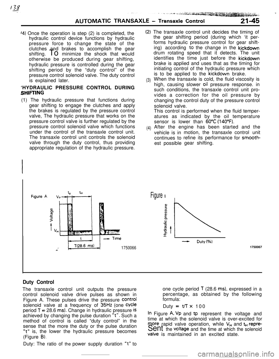
Duty ControlThe transaxle control unit outputs the pressureone cycle period
T (28.6 ms), expressed in a
control solenoid valve drive pulses as shown inpercentage, as obtained by the following
formula:
Figure A. These pulses drive the pressure
COrmIsolenoid valve at a frequency of
35Hz (one Cycleperiod
T = 28.6 ms). Change in hydraulic pressure iSDuty =t/-r x 100
achieved by changing the pulse duration
“t”. Such aIn Figure A, Vp and tp represent the voltage and
method of control is called “duty control” in thetime at which the solenoid valve is over-excited for
sense that the more the duty or the pulse duration
more rapid valve operation, while V,, and t+., repre-
“t” is, the lower the hydraulic pressure becomesSent the v,oltage and the time at which the solenoid(Figure
B).Valve is maintained in an excited state.
Duty: The ratio of the power supply duration
“t” to
Page 273 of 391

.-AUTOMATIC TRANSAXLE
- Transaxle Control21-49
Transaxlecontrol unit
Eel
6017!au72
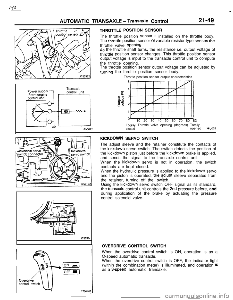
THROmE POSITION SENSOR
The throttle position
SenSOr is installed on the throttle body.
The throttle position sensor Of variable resistor type
senses thethrottle valve
opening.
As the throttle shaft turns, the resistance i.e. output voltage of
throttle position sensor changes. This throttle position sensor
output voltage is input to the transaxle control unit to compute
the throttle opening.
The throttle position sensor output voltage can be adjusted by
turning the throttle position sensor body.
Throttle position sensor output characteristics
5
1
0’ ’10 20 30 40 50 60 70 80 82Totally Throttle valve opening (degrees) Totally
closedopened7FUO75control switchKICKDOWN SERVO SWITCH
The adjust sleeve and the retainer constitute the contacts of
the kickdown servo switch. The switch detects the position of
the kickdown piston just before the kickdown brake is applied,
and sends the signal to the transaxle control unit.
When the kickdown servo is not in operation, the switch
contacts are kept closed.
When the hydraulic pressure is applied to the kickdown servo
and the piston is operated,
the’adjust sleeve separates from
the retainer, turning off the. switch.
Using the kickdown servo switch OFF signal as its standard,
thetransaxle control unit controls the 2nd pressure before, and
during application of the brake by actuating the pressure
control solenoid valve.
OVERDRIVE CONTROL SWITCH
When the overdrive control switch is ON, operation is as a
O-speed automatic transaxle.
When the overdrive control switch is OFF, the indicator light
(within the combination meter) is illuminated, and operation
isas a
3-speed automatic transaxle.