tires MITSUBISHI ECLIPSE 1990 Service Manual
[x] Cancel search | Manufacturer: MITSUBISHI, Model Year: 1990, Model line: ECLIPSE, Model: MITSUBISHI ECLIPSE 1990Pages: 391, PDF Size: 15.27 MB
Page 6 of 391

o-2GENERAL - Technical Features
TECHNICAL FEATURESROOCAAB
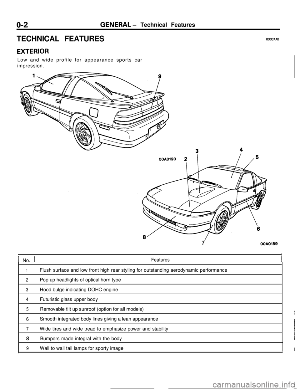
EXTERIORLow and wide profile for appearance sports car
impression.
OOA0190 2
7OOA0189
I
1 No. tFeatures
1Flush surface and low front high rear styling for outstanding aerodynamic performance
2Pop up headlights of optical horn type
3Hood bulge indicating DOHC engine
4Futuristic glass upper body
5Removable tilt up sunroof (option for all models)If
6Smooth integrated body lines giving a lean appearance
7Wide tires and wide tread to emphasize power and stabilityI1
aBumpers made integral with the bodyi
9Wall to wall tail lamps for sporty imageIi
--
Page 23 of 391

FRONT SUSPENSION - Anti-dive Geometry / Negative-offset Geometry2-5ANTI-DIVE GEOMETRY
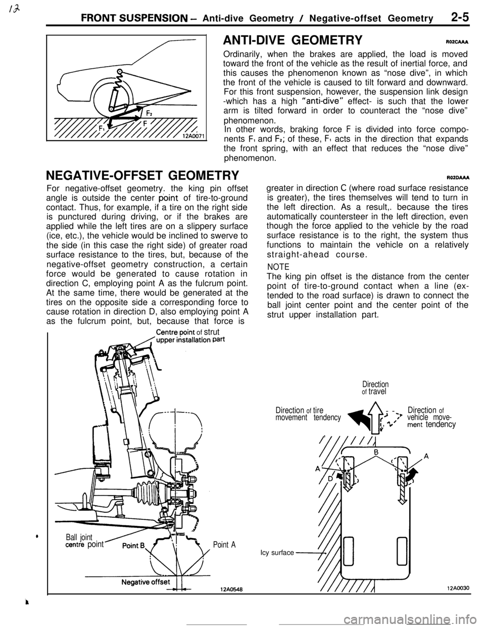
RO2cAAAOrdinarily, when the brakes are applied, the load is moved
toward the front of the vehicle as the result of inertial force, and
this causes the phenomenon known as “nose dive”, in which
the front of the vehicle is caused to tilt forward and downward.
For this front suspension, however, the suspension link design
-which has a high
“anti-dive” effect- is such that the lower
arm is tilted forward in order to counteract the “nose dive”
phenomenon.
In other words, braking force
F is divided into force compo-
nents
F, and F2; of these, F1 acts in the direction that expands
the front spring, with an effect that reduces the “nose dive”
phenomenon.
NEGATIVE-OFFSET GEOMETRY
AOZDAAAFor negative-offset geometry. the king pin offset
angle is outside the center point of tire-to-ground
contact. Thus, for example, if a tire on the right side
is punctured during driving, or if the brakes are
applied while the left tires are on a slippery surface
(ice, etc.), the vehicle would be inclined to swerve to
the side (in this case the right side) of greater road
surface resistance to the tires, but, because of the
negative-offset geometry construction, a certain
force would be generated to cause rotation in
direction C, employing point A as the fulcrum point.
At the same time, there would be generated at the
tires on the opposite side a corresponding force to
cause rotation in direction D, also employing point A
as the fulcrum point, but, because that force is
Centreooint of strutPatigreater in direction
C (where road surface resistance
is greater), the tires themselves will tend to turn in
the left direction. As a result,. because
t.he tires
automatically countersteer in the left direction, even
though the force applied to the vehicle by the road
surface resistance is to the right, the system thus
functions to maintain the vehicle on a relatively
straight-ahead course.
NOTEThe king pin offset is the distance from the center
point of tire-to-ground contact when a line (ex-
tended to the road surface) is drawn to connect the
ball joint center point and the center point of the
strut upper installation part.
Point AIcy surface
12AO548
Ball jointLcentre point
Directionof travel
Direction
of tire
4--
Direction ofmovement tendency>f;’*Jvehicle move-:’
”ment tendency,
12AOO30
Page 198 of 391

---_REAR SUSPENSION
<2WD> - Three-link Suspension17-5
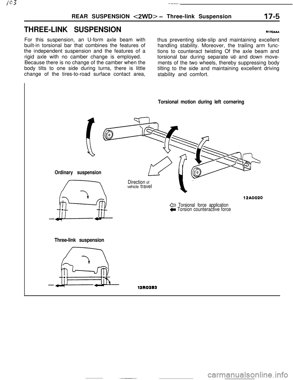
THREE-LINK SUSPENSIONFor this suspension, an U-form axle beam with
built-in torsional bar that combines the features of
the independent suspension and the features of a
rigid axle with no camber change is employed.
Because there is no change of the camber when the
body tilts to one side during turns, there is little
change of the tires-to-road surface contact area,
R1naAAthus preventing side-slip and maintaining excellent
handling stability. Moreover, the trailing arm func-
tions to counteract twisting Of the axle beam and
torsional bar during separate
UP and down move-
ments of the two wheels, thereby suppressing body
tilting to the side and maintaining excellent driving
stability and comfort.
Torsional motion during left cornering
Ordinary suspension
Direction ofvehicle travel
& Torsional force applicationC Torsion counteractive force
Three-link suspension
Page 235 of 391

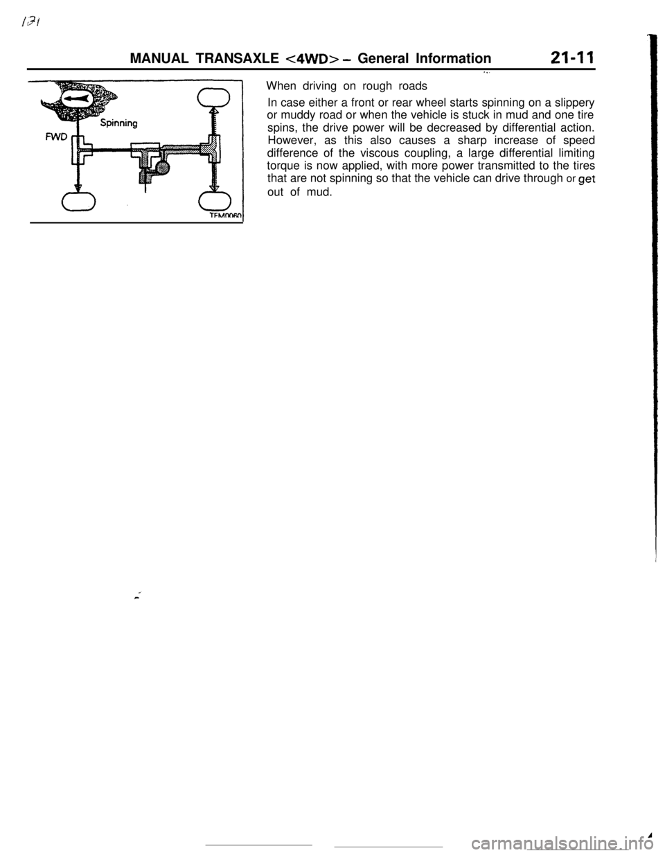
MANUAL TRANSAXLE <4WD> - General Information21-I 1When driving on rough roads. . .In case either a front or rear wheel starts spinning on a slippery
or muddy road or when the vehicle is stuck in mud and one tire
spins, the drive power will be decreased by differential action.
However, as this also causes a sharp increase of speed
difference of the viscous coupling, a large differential limiting
torque is now applied, with more power transmitted to the tires
that are not spinning so that the vehicle can drive through or
getout of mud.A