torque MITSUBISHI ECLIPSE 1990 Service Manual
[x] Cancel search | Manufacturer: MITSUBISHI, Model Year: 1990, Model line: ECLIPSE, Model: MITSUBISHI ECLIPSE 1990Pages: 391, PDF Size: 15.27 MB
Page 9 of 391
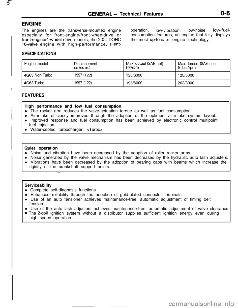
GENERAL - Technical Featureso-5ENGINE
The engines are the transverse-mounted engine
especially for front-engine/front-wheeldrive orfront-engine/4-wheel drive models, the
2.OL DOHC
16-valve engine with high-performance, silent-
operation,low-vibration,low-noise,low-fuel-
consumption features, an engine that fully displays
the most
up-todate engine technology.
SPECIFICATIONS
Engine model
Displacement
cc (cu.in.1
h$xo$put (SAE net)Max. torque (SAE net)
ft.Ibs./rpm
4G63Non-Turbo1997(122)135/6000125/5000
4663Turbo1997(122)195/6000203/3000
FEATURESHigh performance and low fuel consumption
l The rocker arm reduces the valve-actuation torque as well as fuel consumption.
l Air-intake efficiency improved through the adoption of the optimum air-intake system layout.
l Improved response and fuel consumption has been achieved by electronic control multipoint
fuel injection.
l Water-cooled turbocharger.
Quiet operation
l Noise and vibration have been decreased by the adoption of roller rocker arms.
l Noise generated by the valve mechanism has been decreased by the hydraulic auto lash adjusters.
l Vibrations have been decreased by the adoption of bearing caps with beams which increase the
rigidity of the crankshaft support points.
-Serviceability
l Complete self-diagnosis functions.
l Enhanced reliability through the adoption of gold-plated connector terminals.
l Use of an auto tensioner achieves maintenance-free, automatic adjustment of timing belt
tension.
l Use of the auto lash adjusters achieves maintenance-free, automatic adjustment of valve clearance
.o The 2coil ignition system without a distributor supplies sufficient ignition energy even during
high speed operation.
Page 11 of 391
GENERAL -Technical Featureso-74WD
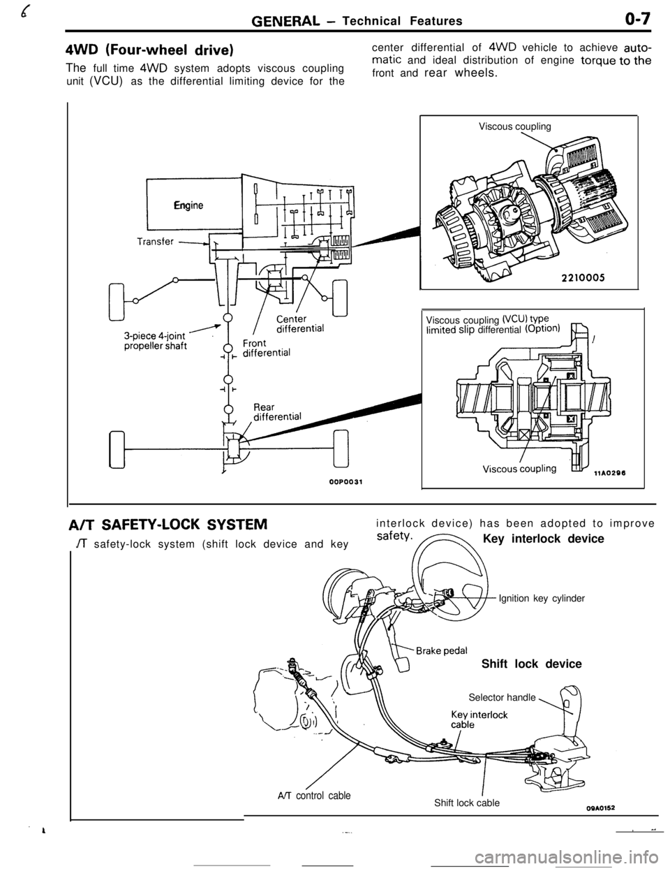
(Four-wheel drive)The full time 4WD system adopts viscous coupling
unit (VCU) as the differential limiting device for thecenter differential of 4WD vehicle to achieve auto-
matic and ideal distribution of engine torque to the
front and rear wheels.
r_
Engine
00P0031Viscous coupling
Viscous coupling
(VCU) VP?limited slip differential (OptIOn)
A/TSAFETY-LOCK SYSTEMinterlock device) has been adopted to improve
JT safety-lock system (shift lock device and keysafety*FNKey interlock device
Ignition key cylinder
Shift lock device
Selector handle
AIT control cableShift lock cable
~ ^.._...
Page 32 of 391
REAR AXLE- Viscous Coupling Type Limited Slip Differential3-a
DIFFERENTIALROlEAM
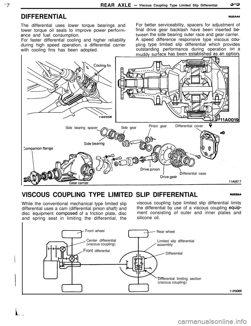
The differential uses lower torque bearings and
lower torque oil seals to improve power perform-
ante and fuel consumption.
For faster differential cooling and higher reliability
during high speed operation, a differential carrier
with cooling fins has been adopted.For better serviceability, spacers for adjustment of
final drive gear backlash have been inserted
be-tween the side bearing outer race and gear carrier.
A speed difference responsive type viscous
cou-
pling type limited slip differential which provides
outstandingperformance during operationon a
Side gearPinion gearDifferential coverQ./\Side bearing spaceifferential case
VISCOUS COUPLING TYPE LIMITED SLIP DIFFERENTIALRWEBAAWhile the conventional mechanical type limited slip
differential uses a cam (differential pinion shaft) and
disc equipment
compo.sed of a friction plate, disc
and spring seat in limiting the differential, theviscous coupling type limited slip differential limits
the differential by use of a viscous coupling equip-
ment consisting of outer and inner plates and
silicone oil.
Front wheel
Center differential
’ (viscous coupling)Rear wheel
Limited slip differential
assembly
Front differential, I
TDifferential
Differential limiting section
(viscous coupling)11KmI66
L.-
Page 33 of 391
3-6REAR AXLE - Viscous Coupling Type Limited Slip Differential
Is
Side gear (L.H.)
Side gear (R.H.)1Differential case B
Pinion shaft
Thrust
washer
Viscous cokpling
3r
Side gear U3.H.)Differential case
B
, ,,Differential cover
I
‘Gear cagierPir
,Drive pinionfront bearing
Driv& pinionDrive gear
Bearing caprear bearing
ICokpanion flangellAo337
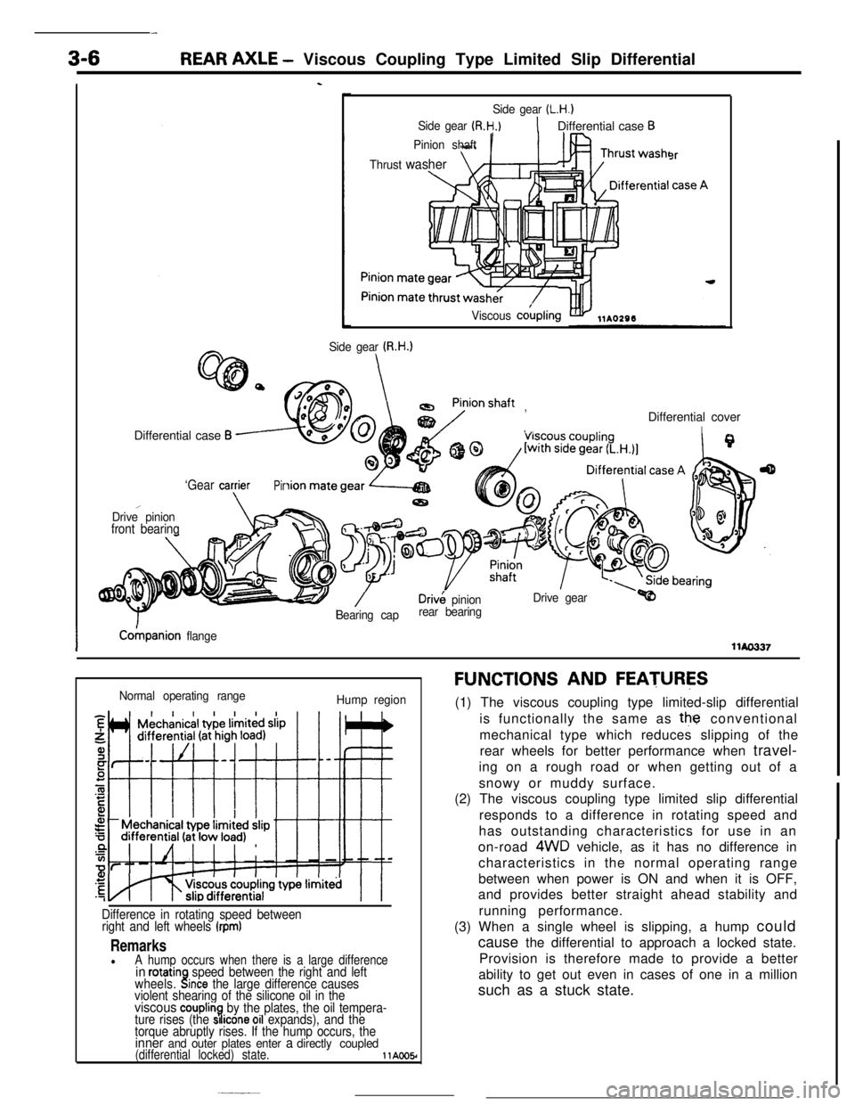
Normal operating range
Hump region
Difference in rotating speed between
right and left wheels (rpm)
RemarkslA hump occurs when there is a large differencein rotatinwheels..!speed between the right and leftlnce the large difference causes
violent shearing of the silicone oil in the
viscous couplin7.by the plates, the oil tempera-
ture rises (the SI Icone 011 expands), and the
torque abruptly rises. If the hump occurs, the
inner and outer plates enter a directly coupled(differential locked) state.llAOO5r
FUNCTIONS AND FEATURES(1) The viscous coupling type limited-slip differential
is functionally the same as
the conventional
mechanical type which reduces slipping of the
rear wheels for better performance when travel-
ing on a rough road or when getting out of a
snowy or muddy surface.
(2) The viscous coupling type limited slip differential
responds to a difference in rotating speed and
has outstanding characteristics for use in an
on-road
4WD vehicle, as it has no difference in
characteristics in the normal operating range
between when power is ON and when it is OFF,
and provides better straight ahead stability and
running performance.
(3) When a single wheel is slipping, a hump could
cause the differential to approach a locked state.
Provision is therefore made to provide a better
ability to get out even in cases of one in a million
such as a stuck state.
Page 35 of 391
w
3-8REAR AXLE - Viscous Coupling Type Limited Slip Differential
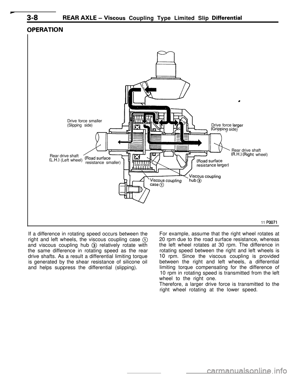
OPERATIONDrive force smaller
I(Slipping side)Drive force larger(Grippina side)
Rear drive shaft
(L.H.1 (Left wheel)
resistance smaller)Rear drive shaft
(R.H.1 (Right wheel)
11 PO071If a difference in rotating speed occurs between the
right and left wheels, the viscous coupling case @
and viscous coupling hub @ relatively rotate with
the same difference in rotating speed as the rear
drive shafts. As a result a differential limiting torque
is generated by the shear resistance of silicone oil
and helps suppress the differential (slipping).For example, assume that the right wheel rotates at
20 rpm due to the road surface resistance, whereas
the left wheel rotates at 30 rpm. The difference in
rotating speed between the right and left wheels is
10 rpm. Since the viscous coupling is provided
between the right and left wheels, a differential
limiting torque compensating for the difference of
10 rpm in rotating speed is transmitted from the left
wheel to the right one.
Therefore, a larger drive force is transmitted to the
right wheel rotating at the lower speed.
Page 99 of 391
ENGINE - Base Engine
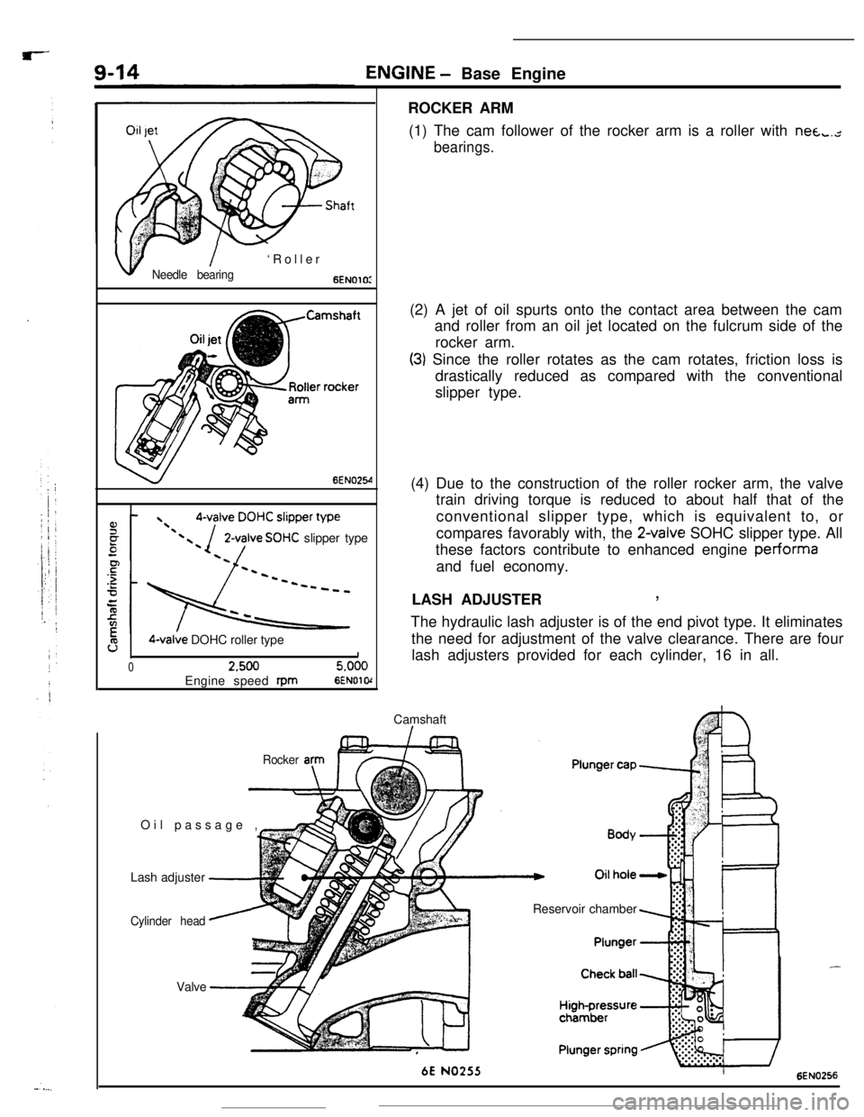
ROCKER ARM
(1) The cam follower of the rocker arm is a roller with nea,.,-
bearings.
v
,I$- I- ‘Roller
Needle bearing6ENOlOI
6EN025-4
2-valve SOHC slipper type
9O-valve DOHC roller type1
02.5005.000Engine speed
rpm6ENOl o(Camshaft
I-Oil passage ,
EIr(2) A jet of oil spurts onto the contact area between the cam
and roller from an oil jet located on the fulcrum side of the
rocker arm.
(3) Since the roller rotates as the cam rotates, friction loss is
drastically reduced as compared with the conventional
slipper type.
(4) Due to the construction of the roller rocker arm, the valve
train driving torque is reduced to about half that of the
conventional slipper type, which is equivalent to, or
compares favorably with, the
2-valve SOHC slipper type. All
these factors contribute to enhanced engine performa
and fuel economy.
LASH ADJUSTER
,The hydraulic lash adjuster is of the end pivot type. It eliminates
the need for adjustment of the valve clearance. There are four
lash adjusters provided for each cylinder, 16 in all.
Rocker anIF=Lash adjuster
-
Cylinder head
--Valve
‘-Reservoir chamber
6E NO255
-6EN0256
Page 107 of 391
9-22ENGINE- Mounts
Principalaxi? of inertia
The
::I: indicates mount positions.01 RO77OlAbsorption action during minute vibrations
ICavity
CavityOlRcl767l
Absorption during large vibrations or “rolling”
Cavity
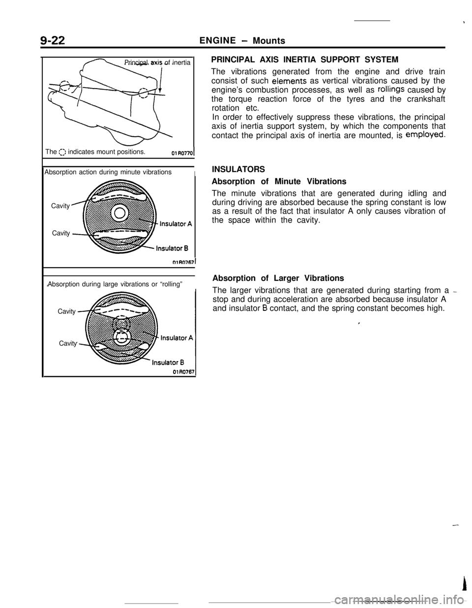
CavityPRINCIPAL AXIS INERTIA SUPPORT SYSTEM
The vibrations generated from the engine and drive train
consist of such eiements as vertical vibrations caused by the
engine’s combustion processes, as well as
rollings caused by
the torque reaction force of the tyres and the crankshaft
rotation etc.
In order to effectively suppress these vibrations, the principal
axis of inertia support system, by which the components that
contact the principal axis of inertia are mounted, is employed.
INSULATORS
Absorption of Minute Vibrations
The minute vibrations that are generated during idling and
during driving are absorbed because the spring constant is low
as a result of the fact that insulator A only causes vibration of
the space within the cavity.
Absorption of Larger Vibrations
The larger vibrations that are generated during starting from a
_stop and during acceleration are absorbed because insulator A
and insulator
B contact, and the spring constant becomes high.
Page 163 of 391
FUEL SYSTEM -Idle Speed Control14-51
_ 0 (32)80 (175)Coolant temperature “C (“F)6FUO2653
ATarget position during operation
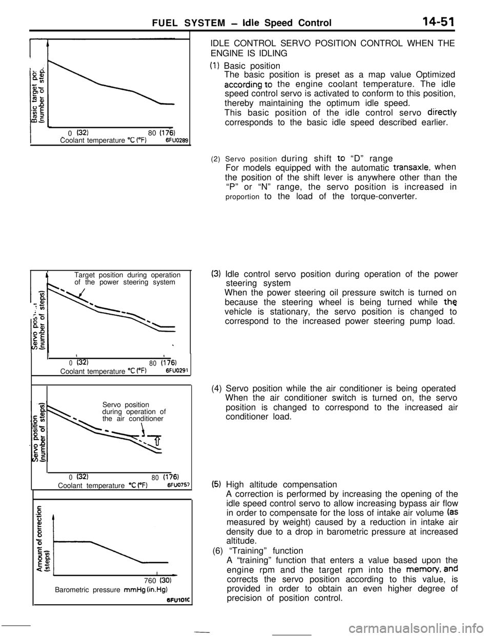
of the power steering systemIDLE CONTROL SERVO POSITION CONTROL WHEN THE
ENGINE IS IDLING
(1) Basic position
The basic position is preset as a map value Optimized
according to the engine coolant temperature. The idle
speed control servo is activated to conform to this position,
thereby maintaining the optimum idle speed.
This basic position of the idle control servo
diiectlycorresponds to the basic idle speed described earlier.
1II
0(32)
80(176)Coolant temperature
“C VW6FUO291Servo position
during operation of
the air conditioner
0(32)
80(176)Coolant temperature “C (“F)6FUO757
1L)760 (30)Barometric pressure mmHg
(in.Hg)BFUlOlC(2) Servo position during shift to “D” range
For models equipped with the automatic
transaxle.when
the position of the shift lever is anywhere other than the
“P” or “N” range, the servo position is increased in
proportion to the load of the torque-converter.
(3) Idle control servo position during operation of the power
steering system
When the power steering oil pressure switch is turned on
because the steering wheel is being turned while
thevehicle is stationary, the servo position is changed to
correspond to the increased power steering pump load.
(4) Servo position while the air conditioner is being operated
When the air conditioner switch is turned on, the servo
position is changed to correspond to the increased air
conditioner load.
(5) High altitude compensation
A correction is performed by increasing the opening of the
idle speed control servo to allow increasing bypass air flow
in order to compensate for the loss of intake air volume
(asmeasured by weight) caused by a reduction in intake air
density due to a drop in barometric pressure at increased
altitude.
(6) “Training” function
A “training” function that enters a value based upon the
engine rpm and the target rpm into the memon/,
andcorrects the servo position according to this value, is
provided in order to obtain an even higher degree of
precision of position control.
Page 200 of 391
/cY
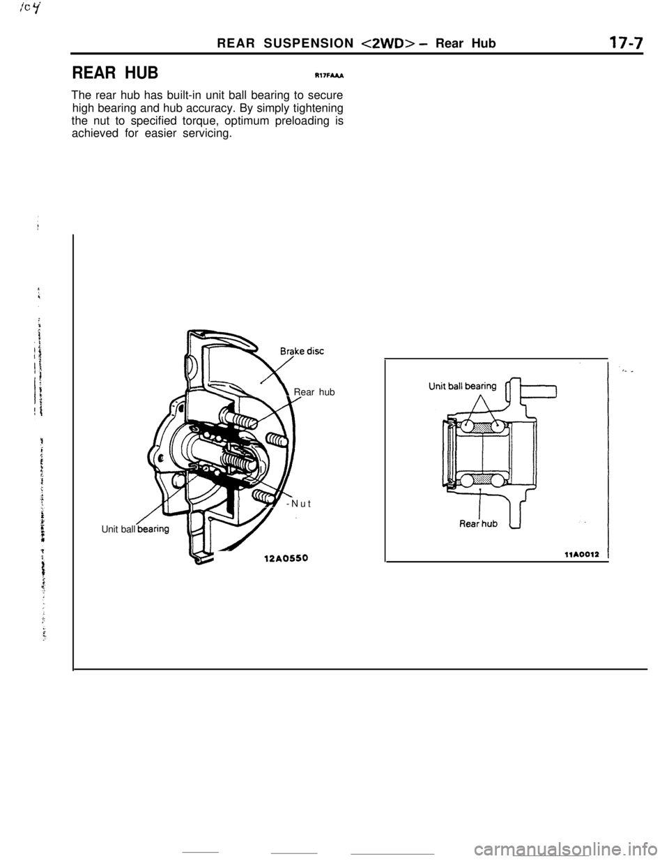
REAR HUBREAR SUSPENSION
<2WD> - Rear Hub
Rl7FMA
17-7The rear hub has built-in unit ball bearing to secure
high bearing and hub accuracy. By simply tightening
the nut to specified torque, optimum preloading is
achieved for easier servicing.
Unit ball
a -\ Rear hub
/‘YLLY -Nut
12A0550
Page 216 of 391
:POWER STEERING
- Pinion and Valve Assembly Construction19-7 ’fOPERATION OF THE PINION AND VALVE
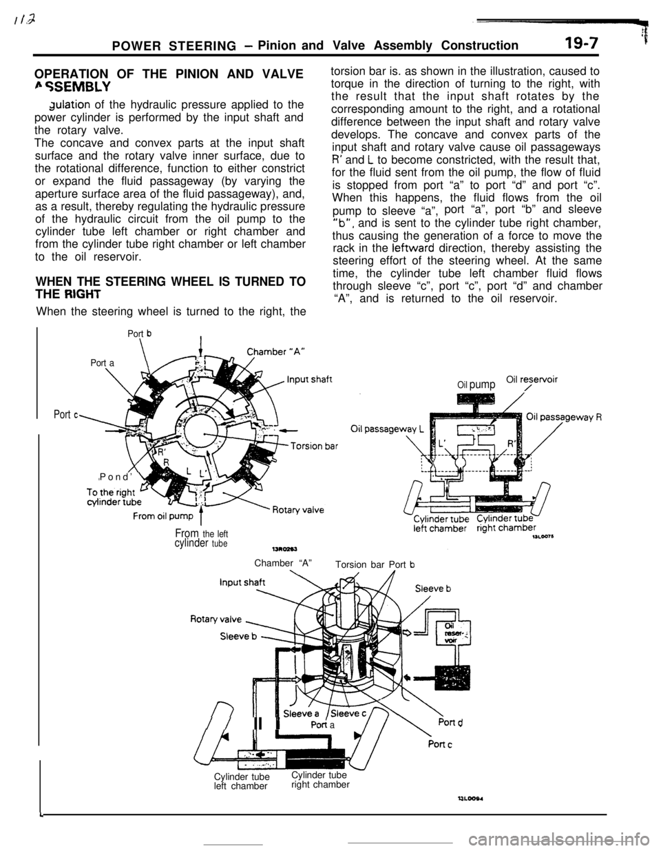
fi %EMBLYdulation of the hydraulic pressure applied to the
power cylinder is performed by the input shaft and
the rotary valve.
The concave and convex parts at the input shaft
surface and the rotary valve inner surface, due to
the rotational difference, function to either constrict
or expand the fluid passageway (by varying the
aperture surface area of the fluid passageway), and,
as a result, thereby regulating the hydraulic pressure
of the hydraulic circuit from the oil pump to the
cylinder tube left chamber or right chamber and
from the cylinder tube right chamber or left chamber
to the oil reservoir.
WHEN THE STEERING WHEEL IS TURNED TOTHE
RIGHTWhen the steering wheel is turned to the right, the
Port b\
Port a\Pond’
Ltorsion bar is. as shown in the illustration, caused to
torque in the direction of turning to the right, with
the result that the input shaft rotates by the
corresponding amount to the right, and a rotational
difference between the input shaft and rotary valve
develops. The concave and convex parts of the
input shaft and rotary valve cause oil passageways
R’ and L to become constricted, with the result that,
for the fluid sent from the oil pump, the flow of fluid
is stopped from port “a” to port “d” and port “c”.
When this happens, the fluid flows from the oil
pump to sleeve “a”,port “a”, port “b” and sleeve
‘lb”, and is sent to the cylinder tube right chamber,
thus causing the generation of a force to move the
rack in the leftward direction, thereby assisting the
steering effort of the steering wheel. At the same
time, the cylinder tube left chamber fluid flows
through sleeve “c”, port “c”, port “d” and chamber
“A”, and is returned to the oil reservoir.
Port c
Oil pumpOil ryetvoir
From the leftcylinder tubeChamber “A”
Torsion bar Port
b
//II YPO< aPond
4Cylinder tube
left chamberCylinder tube
right chamber