torque MITSUBISHI ECLIPSE 1990 Owner's Manual
[x] Cancel search | Manufacturer: MITSUBISHI, Model Year: 1990, Model line: ECLIPSE, Model: MITSUBISHI ECLIPSE 1990Pages: 391, PDF Size: 15.27 MB
Page 247 of 391
I,?+7_-AUTOMATIC TRANSAXLE
- Transaxle Mechanism21-23
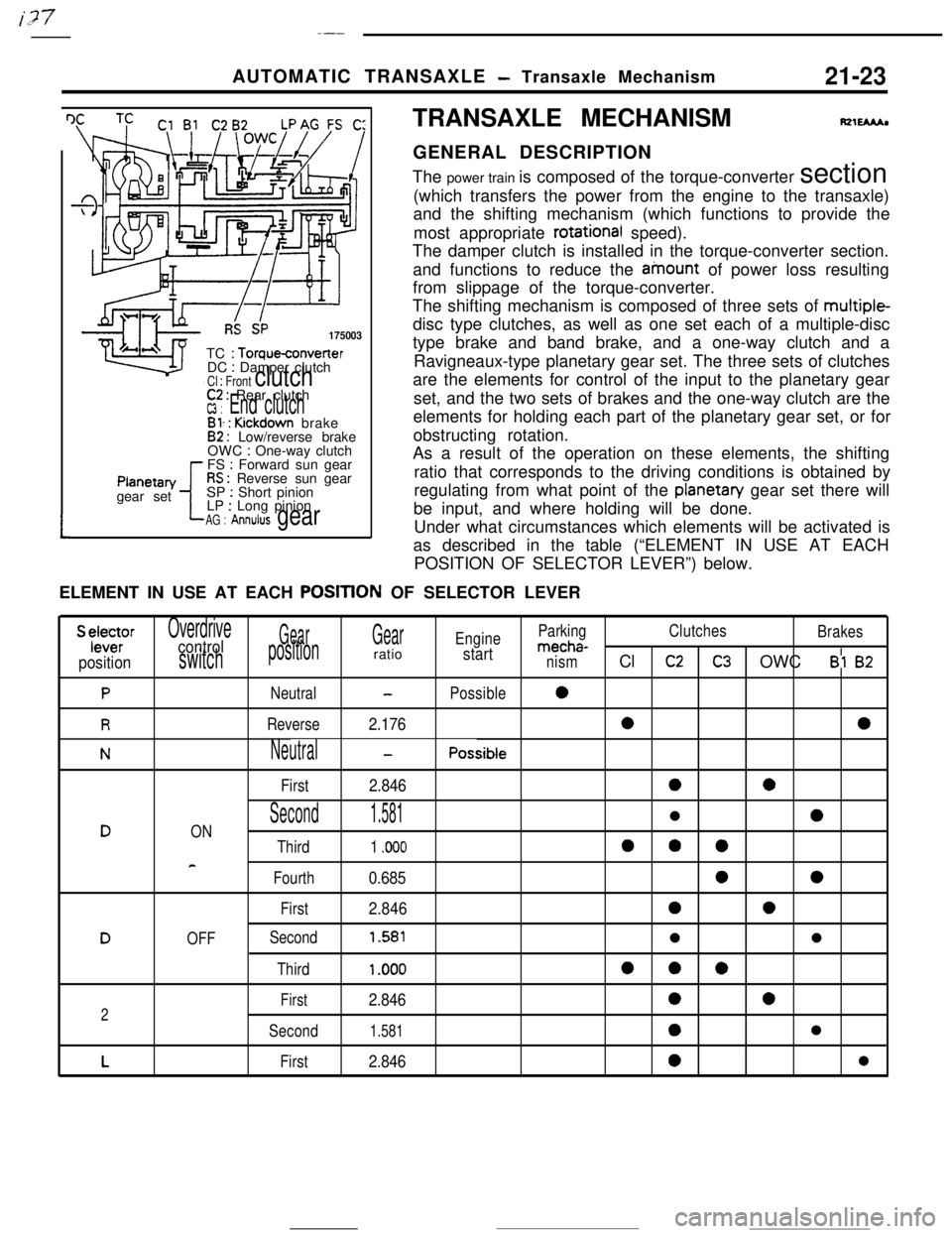
I IRS SP175003TC
: Torqueconverter
DC : Damper clutchCl : Front clutch
tPlanetan/
gear set
C2 : Rear clutchW : End clutchBl. : Kickdown brake82 : Low/reverse brake
OWC : One-way clutch
FS : Forward sun gearRS : Reverse sun gear
SP : Short pinion
LP : Long pinionAG : Annulus gearTRANSAXLE MECHANISM
fQlEMhGENERAL DESCRIPTION
The power train is composed of the torque-converter section
(which transfers the power from the engine to the transaxle)
and the shifting mechanism (which functions to provide the
most appropriate
rotational speed).
The damper clutch is installed in the torque-converter section.
and functions to reduce the ainount of power loss resulting
from slippage of the torque-converter.
The shifting mechanism is composed of three sets of multiple-
disc type clutches, as well as one set each of a multiple-disc
type brake and band brake, and a one-way clutch and a
Ravigneaux-type planetary gear set. The three sets of clutches
are the elements for control of the input to the planetary gear
set, and the two sets of brakes and the one-way clutch are the
elements for holding each part of the planetary gear set, or for
obstructing rotation.
As a result of the operation on these elements, the shifting
ratio that corresponds to the driving conditions is obtained by
regulating from what point of the
planetan/ gear set there will
be input, and where holding will be done.
Under what circumstances which elements will be activated is
as described in the table (“ELEMENT IN USE AT EACH
POSITION OF SELECTOR LEVER”) below.
ELEMENT IN USE AT EACH
POSITtON OF SELECTOR LEVER
S ylele~rOverdriveGearGearEngineParkingClutches
Brakescontrolmecha-
positionswitchpositionratiostartnismCl c2C3 OWC Bl 82
PNeutral-Possible0
RReverse2.17600
NNeutral-Possible
First
2.8460a
Second1.581l0DON
Third1 .ooo000
e
Fourth0.68500
First2.84600
DOFFSecond1.581ll
Third1 .ooo000
First2.846002
Second1.5810l
LFirst2.8460l
Page 257 of 391
AUTOMATIC TRANSAXLE - Transaxle Mechanism21-33
POWER FLOW
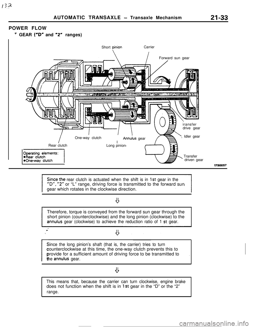
T GEAR (“D” and ‘2” ranges)
Short
DinionCarrier
IForward sun gear
IOne-way clutch
IAnn&s gear
Rear clutch
-1Long pinioniransfer
drive gear
, Idler gear
Transfer* driven gear
17!50057
rear clutch is actuated when the shift is in 1 st gear in the
“D”. “2” or “L” range, driving force is transmitted to the forward sun
gear which rotates in the clockwise direction.
ITherefore, torque is conveyed from the forward sun gear through the
short pinion (counterclockwise) and the long pinion (clockwise) to theannulus gear (clockwise) to achieve the reduction ratio of 1 st gear.
Since the long pinion’s shaft (that is, the carrier) tries to turn
/counterclockwise at this time, the one-way clutch prevents this to
provide for a sufficient amount of driving force to be transmitted to
.
the annulus gear.
,
This means that, because the carrier can turn clockwise, engine brakedoes not function when the shift is in
1 st gear in the “D” or the “2”
range.
Page 259 of 391
2ND’ GEARAUTOMATIC
TRANSAXLE - Transaxle Mechanism21-35
Kickdown brake
I
Shon pinion
\Forward sun gear
1.//LT.//. , ,’ .‘,,i.:,;:.:‘.,.‘,\/
/
Annulus gearLong pinion
Rear clutch/Reverse sun gear
fharatinn damants:
-, IWI WUIUI IWickdown brakeI
.
c
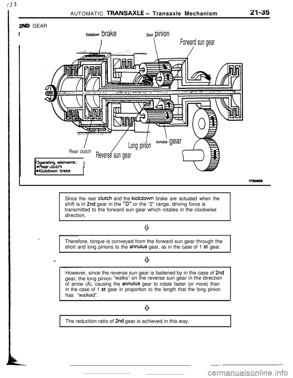
Since the rear clutch and the kickdown brake are actuated when theshift is in
2nd gear in the “0” or the “2” range, driving force is
transmitted to the forward sun gear which rotates in the clockwise
direction,
Therefore, torque is conveyed from the forward sun gear through the
short and long pinions to the annulus gear, as in the case of 1 st gear.
--However, since the reverse sun gear is fastened by in the case of
2ndgear, the long pinion“walks” on the reverse sun gear in the direction
of arrow (A), causing the annulus gear to rotate faster (or more) than
in the case of 1 st
gear in proportion to the length that the long pinionhas “walked”.
The reduction ratio of
2nd gear is achieved in this way.
---
Page 270 of 391
---21-46AUTOMATIC TRANSAXLE
- Transaxle Control
Figure A
IICITime (sec.)f
IiFigureB ,
II
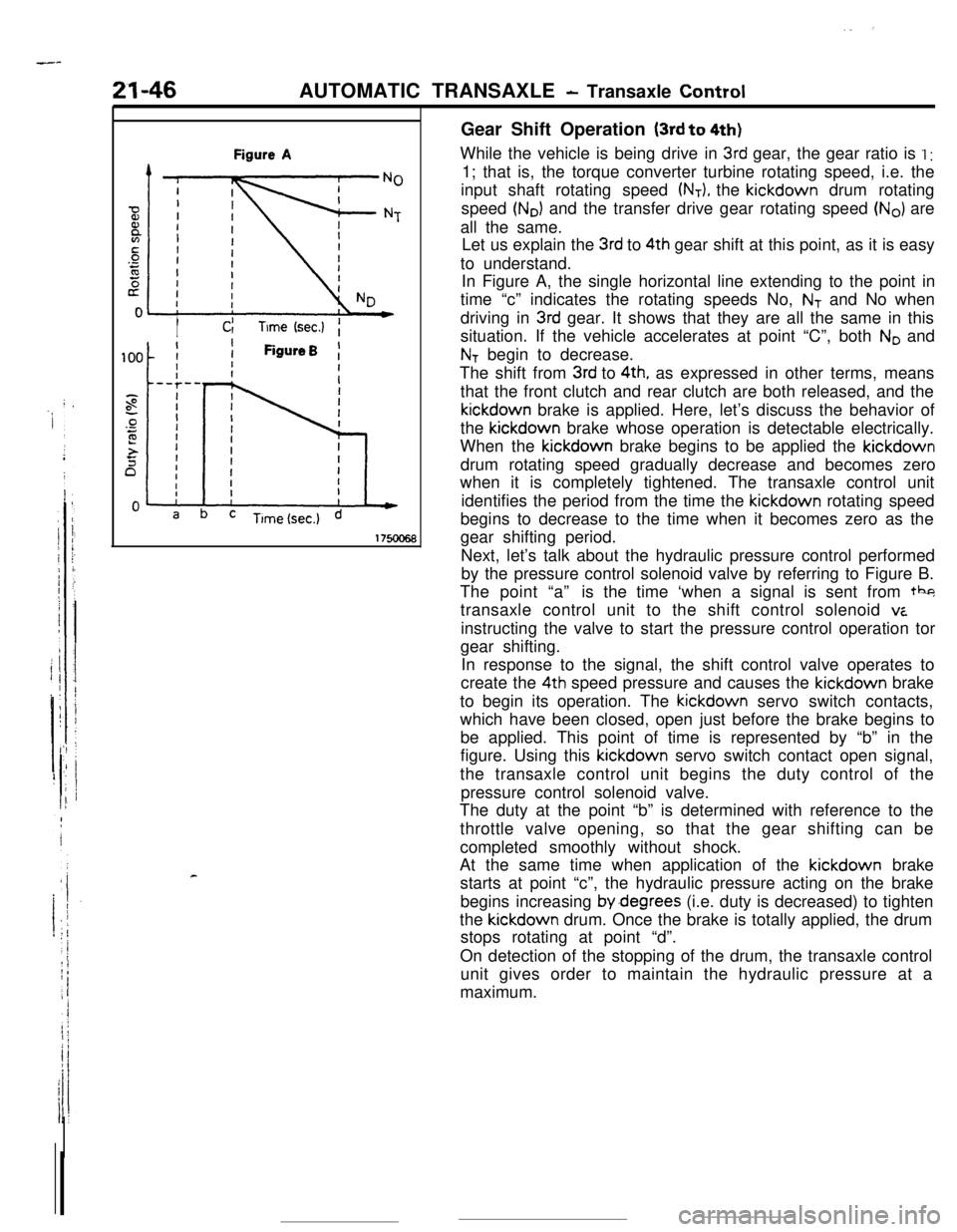
cGear Shift Operation
(3rd to 4th)While the vehicle is being drive in
3rd gear, the gear ratio is I :1; that is, the torque converter turbine rotating speed, i.e. the
input shaft rotating speed
(NT), the kickdown drum rotating
speed
(No) and the transfer drive gear rotating speed (No) are
all the same.
Let us explain the
3rd to 4th gear shift at this point, as it is easy
to understand.
In Figure A, the single horizontal line extending to the point in
time “c” indicates the rotating speeds No,
NT and No when
driving in
3rd gear. It shows that they are all the same in this
situation. If the vehicle accelerates at point “C”, both
No and
NT begin to decrease.
The shift from
3rd to 4th, as expressed in other terms, means
that the front clutch and rear clutch are both released, and thekickdown brake is applied. Here, let’s discuss the behavior of
the kickdown brake whose operation is detectable electrically.
When the kickdown brake begins to be applied the kickdown
drum rotating speed gradually decrease and becomes zero
when it is completely tightened. The transaxle control unit
identifies the period from the time the kickdown rotating speed
begins to decrease to the time when it becomes zero as the
gear shifting period.
Next, let’s talk about the hydraulic pressure control performed
by the pressure control solenoid valve by referring to Figure B.
The point “a”is the time ‘when a signal is sent from tbg
transaxle control unit to the shift control solenoid
viinstructing the valve to start the pressure control operation tor
gear shifting.
In response to the signal, the shift control valve operates to
create the 4th speed pressure and causes the kickdown brake
to begin its operation. The kickdown servo switch contacts,
which have been closed, open just before the brake begins to
be applied. This point of time is represented by “b” in the
figure. Using this kickdown servo switch contact open signal,
the transaxle control unit begins the duty control of the
pressure control solenoid valve.
The duty at the point “b” is determined with reference to the
throttle valve opening, so that the gear shifting can be
completed smoothly without shock.
At the same time when application of the kickdown brake
starts at point “c”, the hydraulic pressure acting on the brake
begins increasing by.degrees (i.e. duty is decreased) to tighten
the kickdown drum. Once the brake is totally applied, the drum
stops rotating at point “d”.
On detection of the stopping of the drum, the transaxle control
unit gives order to maintain the hydraulic pressure at a
maximum.
Page 279 of 391
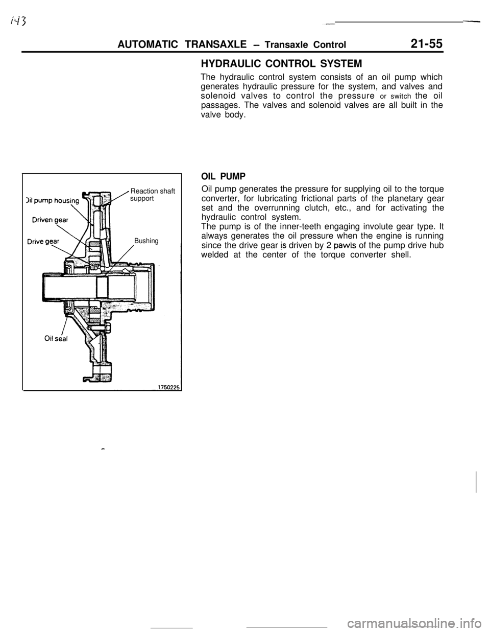
AUTOMATIC TRANSAXLE - Transaxle Control21-55HYDRAULIC CONTROL SYSTEM
Reaction shaft
support
BushingThe hydraulic control system consists of an oil pump which
generates hydraulic pressure for the system, and valves and
solenoid valves to control the pressure or switch the oil
passages. The valves and solenoid valves are all built in the
valve body.
OIL PUMPOil pump generates the pressure for supplying oil to the torque
converter, for lubricating frictional parts of the planetary gear
set and the overrunning clutch, etc., and for activating the
hydraulic control system.
The pump is of the inner-teeth engaging involute gear type. It
always generates the oil pressure when the engine is running
since the drive gear
is driven by 2 pawls of the pump drive hub
welded at the center of the torque converter shell.
Page 280 of 391
-
!-I
I!I
21-56AUTOMATIC TRANSAXLE - Transaxle Control~-REGULATOR VALVE
To torque convener
control valve
t
Toshift control valve,
pressure control valve
and N-D control valve(in “D”. ”2” or “L” range)
“D”.“2” or “L” range)
Oil filter
I1
To N-R control valve(in “R” range)Line relief valve
Oil pan
l
1750076
! To torque convener
IL‘I:control valve
Line pressure Pump
Li Ae(from oil pump) suctionprest$$)7,This
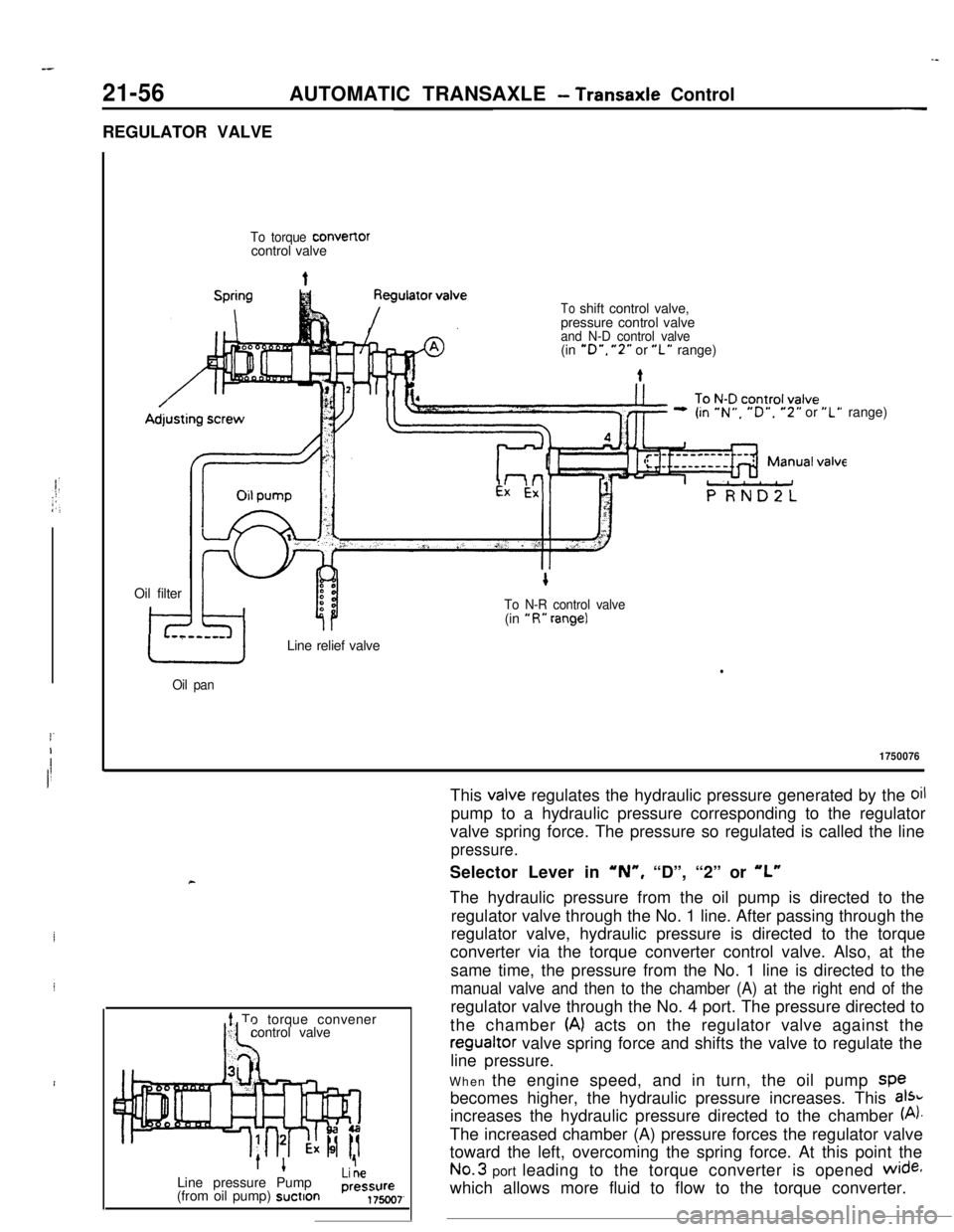
valve regulates the hydraulic pressure generated by the oilpump to a hydraulic pressure corresponding to the regulator
valve spring force. The pressure so regulated is called the line
pressure.Selector Lever in
‘N”, “D”, “2” or “L”The hydraulic pressure from the oil pump is directed to the
regulator valve through the No. 1 line. After passing through the
regulator valve, hydraulic pressure is directed to the torque
converter via the torque converter control valve. Also, at the
same time, the pressure from the No. 1 line is directed to the
manual valve and then to the chamber (A) at the right end of theregulator valve through the No. 4 port. The pressure directed to
the chamber
(A) acts on the regulator valve against theregualtor valve spring force and shifts the valve to regulate the
line pressure.
When the engine speed, and in turn, the oil pump spe
becomes higher, the hydraulic pressure increases. This
aI%increases the hydraulic pressure directed to the chamber
(A).The increased chamber (A) pressure forces the regulator valve
toward the left, overcoming the spring force. At this point theNo.3 port leading to the torque converter is opened
wide+which allows more fluid to flow to the torque converter.
Page 281 of 391
AUTOMATIC TRANSAXLE - Transaxle Control21-57
-7.To torque convert,erLine pressure
’Pump(from oil pump) suction
1 To N-RI control valveLine pressure
(from oil pump)1750072
-#5
To N-Dcontrol
valve
To toraueconverter
AdjLine pressure
1+(from oil pump)Pumpsuction
1 ~7valve
To N-Dcontrol
valve
s
Line pressure
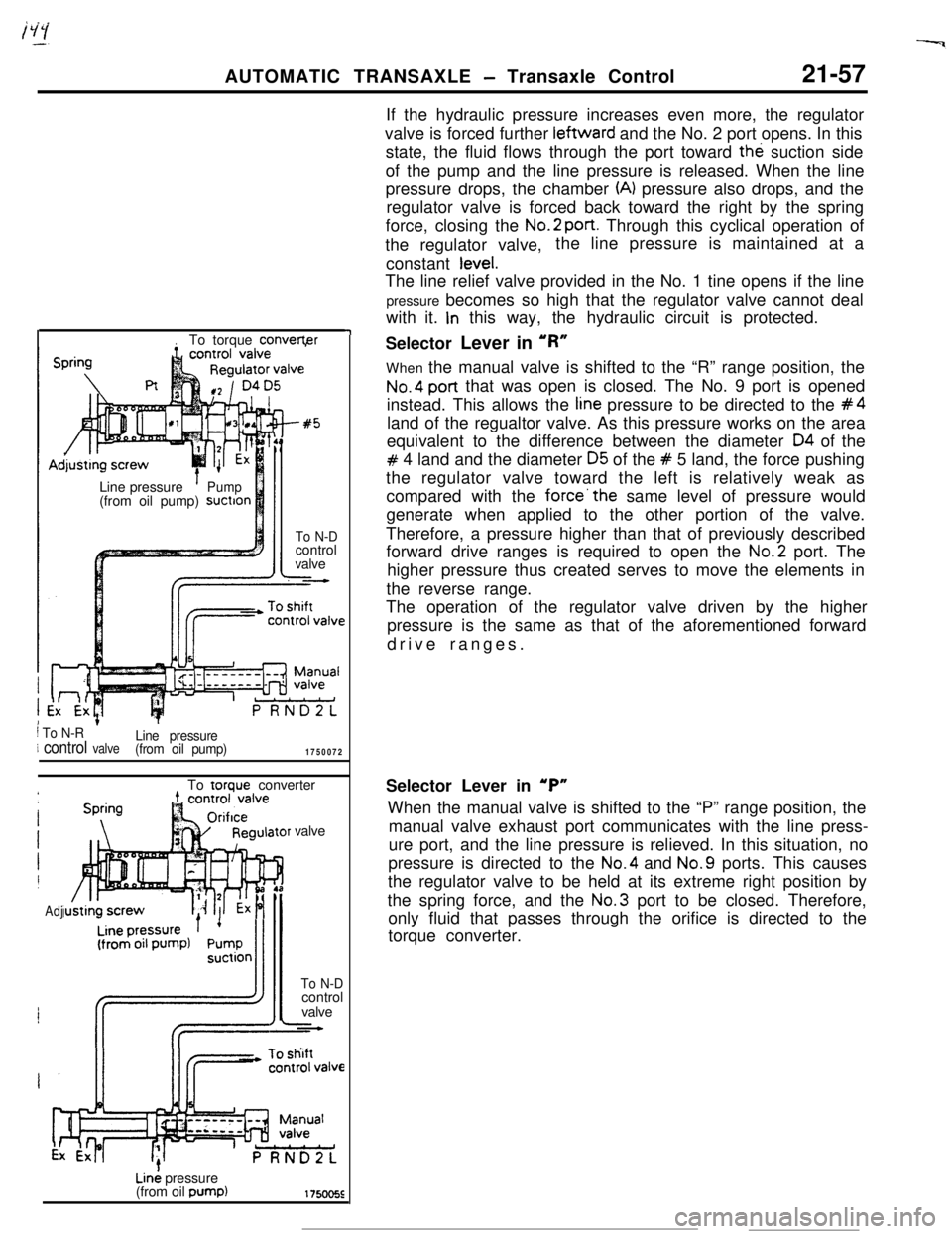
(from oil pump)If the hydraulic pressure increases even more, the regulator
valve is forced further leftward and the No. 2 port opens. In this
state, the fluid flows through the port toward the suction side
of the pump and the line pressure is released. When the line
pressure drops, the chamber
(A) pressure also drops, and the
regulator valve is forced back toward the right by the spring
force, closing the No.2
port. Through this cyclical operation of
the regulator valve,the line pressure is maintained at a
constant
tevel.The line relief valve provided in the No. 1 tine opens if the line
pressure becomes so high that the regulator valve cannot deal
with it.
In this way, the hydraulic circuit is protected.
Selector Lever in ‘R”
When the manual valve is shifted to the “R” range position, the
No.4 post that was open is closed. The No. 9 port is opened
instead. This allows the
tine pressure to be directed to the #4land of the regualtor valve. As this pressure works on the area
equivalent to the difference between the diameter
04 of the
# 4 land and the diameter 05 of the # 5 land, the force pushing
the regulator valve toward the left is relatively weak as
compared with the
force’the same level of pressure would
generate when applied to the other portion of the valve.
Therefore, a pressure higher than that of previously described
forward drive ranges is required to open the No.2 port. The
higher pressure thus created serves to move the elements in
the reverse range.
The operation of the regulator valve driven by the higher
pressure is the same as that of the aforementioned forward
drive ranges.
Selector Lever in
‘P”When the manual valve is shifted to the “P” range position, the
manual valve exhaust port communicates with the line press-
ure port, and the line pressure is relieved. In this situation, no
pressure is directed to the No.4 and No.9 ports. This causes
the regulator valve to be held at its extreme right position by
the spring force, and the No.3 port to be closed. Therefore,
only fluid that passes through the orifice is directed to the
torque converter.
Page 282 of 391
21-58AUTOMATIC TRANSAXLE - Transaxle Control
1750227
To torqueconverter
Pump suction
h& regulator
side1750081
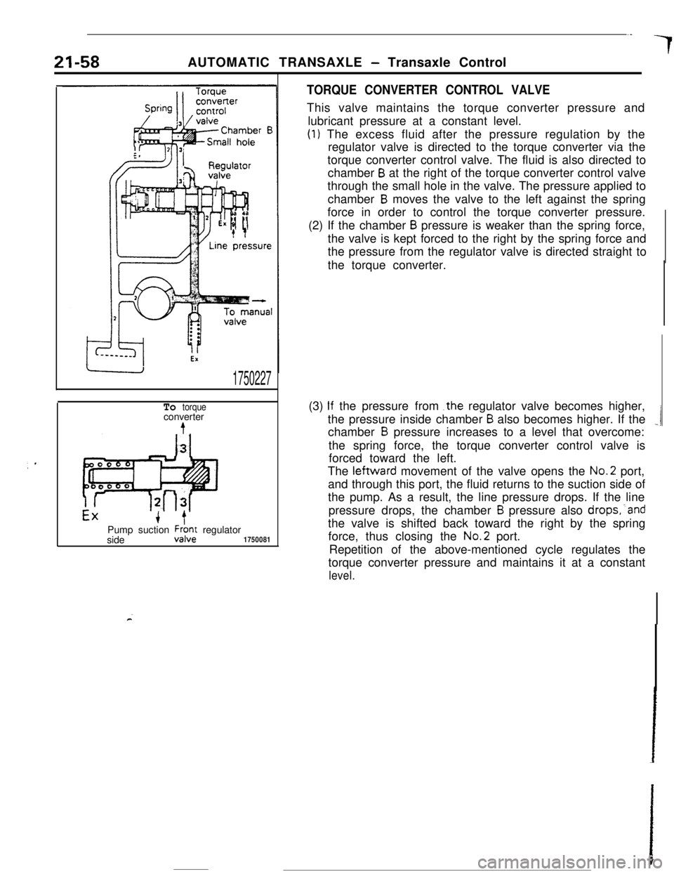
TORQUE CONVERTER CONTROL VALVEThis valve maintains the torque converter pressure and
lubricant pressure at a constant level.
(1) The excess fluid after the pressure regulation by the
regulator valve is directed to the torque converter via the
torque converter control valve. The fluid is also directed to
chamber
B at the right of the torque converter control valve
through the small hole in the valve. The pressure applied to
chamber
B moves the valve to the left against the spring
force in order to control the torque converter pressure.
(2) If the chamber
B pressure is weaker than the spring force,
the valve is kept forced to the right by the spring force and
the pressure from the regulator valve is directed straight to
the torque converter.
(3)
If the pressurefrom .the regulator valve becomes higher,
the pressure inside chamber
B also becomes higher. If the_1chamber B pressure increases to a level that overcome:
the spring force, the torque converter control valve is
forced toward the left.
The leftward movement of the valve opens the No.2 port,
and through this port, the fluid returns to the suction side of
the pump. As a result, the line pressure drops. If the line
pressure drops, the chamber
B pressure also drops,‘and
the valve is shifted back toward the right by the spring
force, thus closing the No.2 port.
Repetition of the above-mentioned cycle regulates the
torque converter pressure and maintains it at a constant
level.
Page 283 of 391
/ii>--..AUTOMATIC TRANSAXLE
- Transaxle Control21-59
Sxxrolvalve175022E
6
LmeFrom
TooilFrompressure torque- pump 2;0%conver-
termntrd
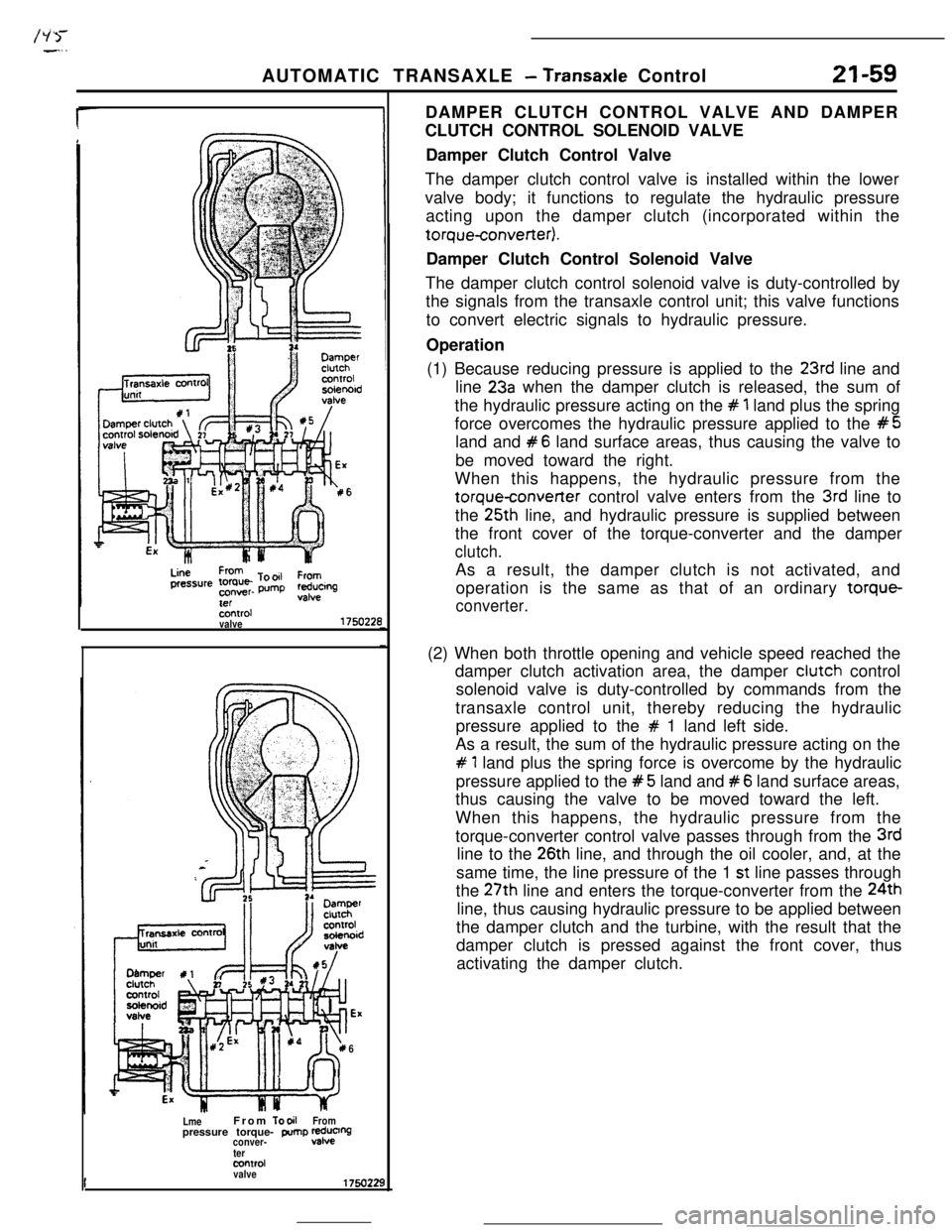
valveDAMPER CLUTCH CONTROL VALVE AND DAMPER
CLUTCH CONTROL SOLENOID VALVE
Damper Clutch Control Valve
The damper clutch control valve is installed within the lower
valve body; it functions to regulate the hydraulic pressure
acting upon the damper clutch (incorporated within thetorqueconverter).
Damper Clutch Control Solenoid Valve
The damper clutch control solenoid valve is duty-controlled by
the signals from the transaxle control unit; this valve functions
to convert electric signals to hydraulic pressure.
Operation
(1) Because reducing pressure is applied to the
23rd line and
line
23a when the damper clutch is released, the sum of
the hydraulic pressure acting on the
# 1 land plus the spring
force overcomes the hydraulic pressure applied to the
#5land and
#6 land surface areas, thus causing the valve to
be moved toward the right.
When this happens, the hydraulic pressure from the
torqueconverter control valve enters from the 3rd line to
the 25th line, and hydraulic pressure is supplied between
the front cover of the torque-converter and the damper
clutch.As a result, the damper clutch is not activated, and
operation is the same as that of an ordinary torque-
converter.(2) When both throttle opening and vehicle speed reached the
damper clutch activation area, the damper clutch control
solenoid valve is duty-controlled by commands from the
transaxle control unit, thereby reducing the hydraulic
pressure applied to the
# 1 land left side.
As a result, the sum of the hydraulic pressure acting on the
# 1 land plus the spring force is overcome by the hydraulic
pressure applied to the
#5 land and #6 land surface areas,
thus causing the valve to be moved toward the left.
When this happens, the hydraulic pressure from the
torque-converter control valve passes through from the
3rdline to the
26th line, and through the oil cooler, and, at the
same time, the line pressure of the 1
st line passes through
the 27th line and enters the torque-converter from the 24th
line, thus causing hydraulic pressure to be applied between
the damper clutch and the turbine, with the result that the
damper clutch is pressed against the front cover, thus
activating the damper clutch.
Page 309 of 391
AUTOMATIC TRANSAXLE - ~kmucle ControlHWBRAULIC
ClRCUlT
S.XTOR LEVER IN “N”Torque-converterKickdown servo
FrontRearu)w-reverse =.I 1~
clutchclutchbrakeclutch
r-m I
-amper clutchIhOlJenoid valve
Oil -filter,
IIShi LroI3,
Lii PressureTorque-converter pressureand
lubriition oil pressureReducing pressurePump suction pressure
Lii Pressure(control pressure)
PCSV control pressureDamper clutch pressure
DCCSV control pressure
I1760224
A