transmission MITSUBISHI ECLIPSE 1990 Service Manual
[x] Cancel search | Manufacturer: MITSUBISHI, Model Year: 1990, Model line: ECLIPSE, Model: MITSUBISHI ECLIPSE 1990Pages: 391, PDF Size: 15.27 MB
Page 8 of 391
o-4GENERAL - Technical Features
BASIC CONSTRUCTION
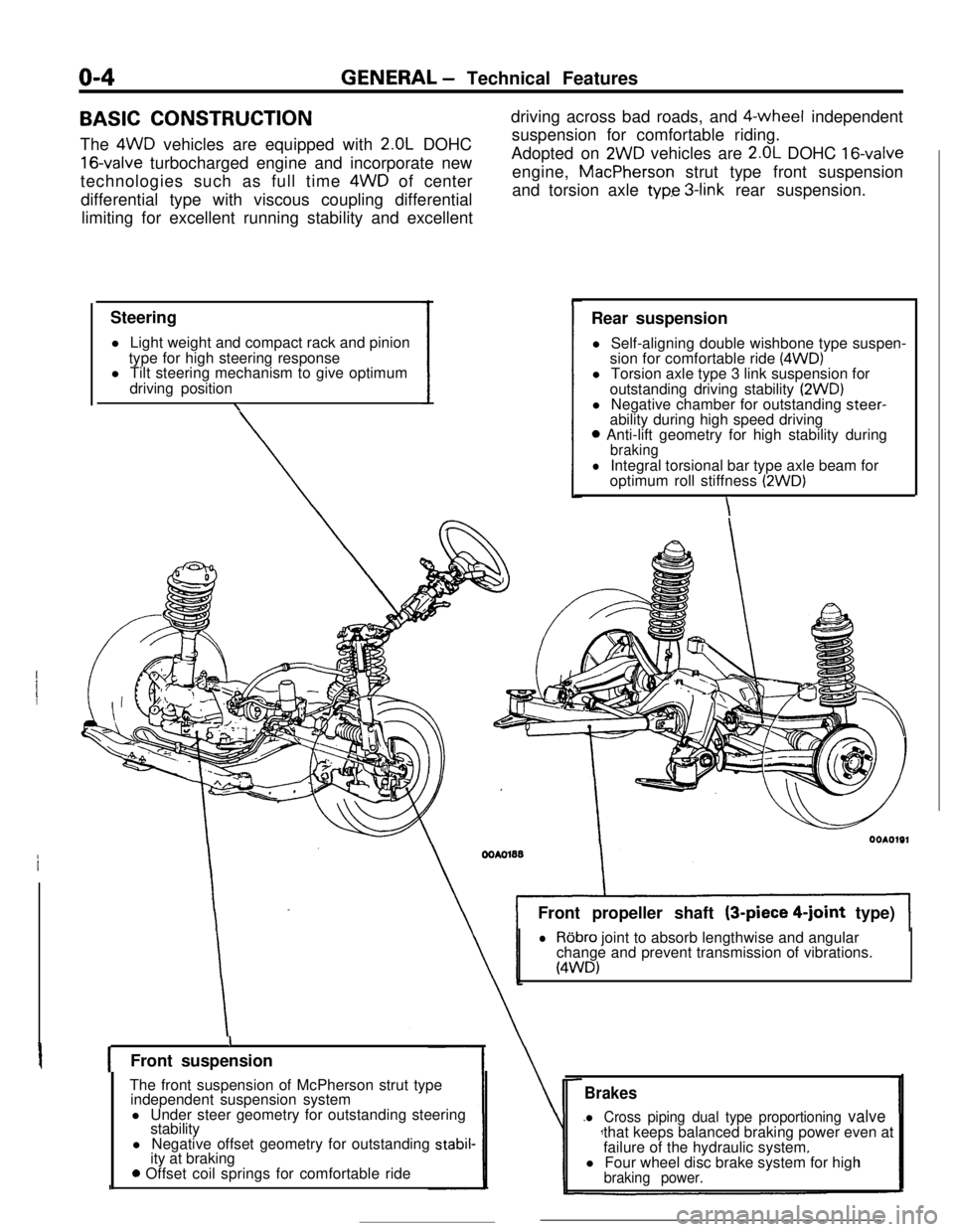
The 4WD vehicles are equipped with
2.OL DOHC
16-valve turbocharged engine and incorporate new
technologies such as full time 4WD of center
differential type with viscous coupling differential
limiting for excellent running stability and excellent
Steering
l Light weight and compact rack and pinion
type for high steering response
l Tilt steering mechanism to give optimum
driving position
\driving across bad roads, and $-wheel independent
suspension for comfortable riding.
Adopted on
2WD vehicles are 2.OL DOHC 16-valveengine, MacPherson strut type front suspension
and torsion axle
typ.e 3-link rear suspension.
Rear suspension
l Self-aligning double wishbone type suspen-
sion for comfortable ride
(4WD)l Torsion axle type 3 link suspension for
outstanding driving stability
(2WD)l Negative chamber for outstanding steer-
ability during high speed driving
0 Anti-lift geometry for high stability duringbraking
lIntegral torsional bar type axle beam for
optimum roll stiffness (2WD)
\Front propeller shaft (3-piece
4-joint type)
lRobro joint to absorb lengthwise and angular
change and prevent transmission of vibrations.
(4WD)
IFront suspension
The front suspension of McPherson strut type
independent suspension system
l Under steer geometry for outstanding steering
stability
l Negative offset geometry for outstanding
stabil-ity at braking
0 Offset coil springs for comfortable ride
Brakes
l Cross piping dual type proportioning valvethat keeps balanced braking power even at
failure of the hydraulic system.
l Four wheel disc brake system for high
braking power.
Page 26 of 391
2-8FRONT SUSPENSION - Front Axle
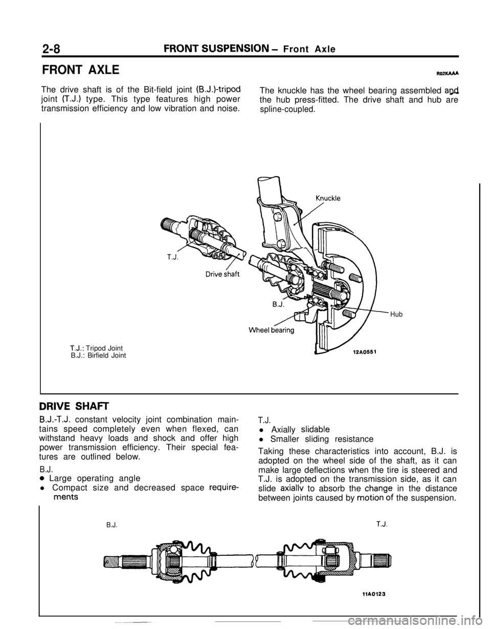
FRONT AXLEROPKAAAThe drive shaft is of the Bit-field joint
(B.J.)-tripodjoint
(T.J.) type. This type features high power
transmission efficiency and low vibration and noise.The knuckle has the wheel bearing assembled
a@the hub press-fitted. The drive shaft and hub are
spline-coupled.
T.J.: Tripod Joint
B.J.: Birfield Joint
Hub
DRIVE SHAFT
B.J.-T.J. constant velocity joint combination main-
tains speed completely even when flexed, can
withstand heavy loads and shock and offer high
power transmission efficiency. Their special fea-
tures are outlined below.
B.J.T.J.l Axially
slidablel Smaller sliding resistance
0 Large operating angle
l Compact size and decreased space
require-
me&Taking these characteristics into account, B.J. is
adopted on the wheel side of the shaft, as it can
make large deflections when the tire is steered and
T.J. is adopted on the transmission side, as it can
slide
axiallv to absorb the chanae in the distance
between joints caused by
motionWof the suspension.
B.J.T.J.
llA0123
Page 106 of 391
L1ENGINE
- Mounts9-21MOUNTS
Rost3u
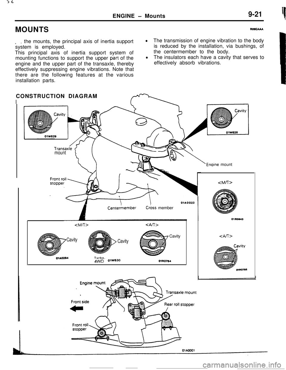
. *the mounts, the principal axis of inertia support
system is employed.
This principal axis of inertia support system of
mounting functions to support the upper
part of the
engine and the upper part of the transaxle, thereby
effectively suppressing engine vibrations. Note that
there are the following features at the various
installation parts.
lThe transmission of engine vibration to the body
is reduced by the installation, via bushings, of
the centermember to the body.
lThe insulators each have a cavity that serves to
effectively absorb vibrations.
CONSTRUCTION DIAGRAM
I
Transaxlemount
‘i::
+g
/v 1b-8
8-,
Enaine mount
A
CenterkemberC&s member
Cavity
CavityCavityolAO284Turbo.
4WD 0lW630OlRO764
Page 112 of 391
INTAKE AND EXHAUST - Exhaust PipeII-5
EXHAUST PIPERllDAM
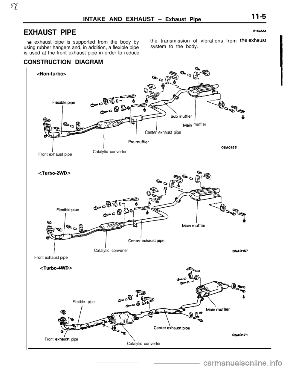
,le exhaust pipe is supported from the body by
using rubber hangers and, in addition, a flexible pipe
is used at the front exhaust pipe in order to reducethe transmission of vibrations from the exhaust
system to the body.
CONSTRUCTION DIAGRAM
Center exhaust pipeFront exhaust pipe
IPm-muffler
Catalytic converter
Imuffler
IFront exhaust pipeCatalytic convener
Flexible pipe,05AO155
05A0157
Front exhakt pipeCatalytic converter
Page 128 of 391
14-16FUEL SYSTEM - Sensors
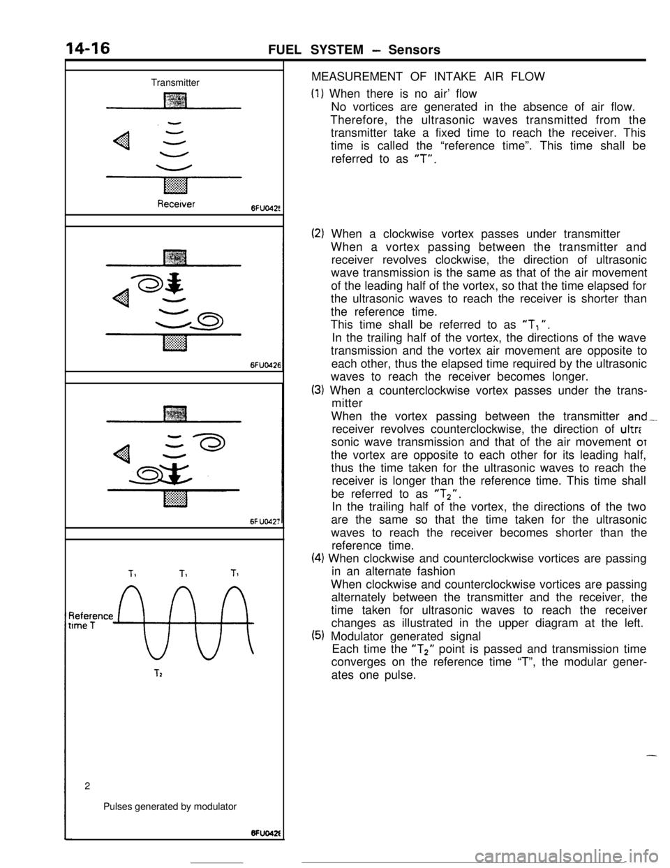
TransmitterMEASUREMENT OF INTAKE AIR FLOW
(1) When there is no air’ flow
No vortices are generated in the absence of air flow.
Therefore, the ultrasonic waves transmitted from the
transmitter take a fixed time to reach the receiver. This
time is called the “reference time”. This time shall be
referred to as
“T”.
Recetver6FUo42!
6FUO426
6f UO42;
TIT1Tl
~tee;ence
9%
T22
Pulses generated by modulator
(2) When a clockwise vortex passes under transmitter
When a vortex passing between the transmitter and
receiver revolves clockwise, the direction of ultrasonic
wave transmission is the same as that of the air movement
of the leading half of the vortex, so that the time elapsed for
the ultrasonic waves to reach the receiver is shorter than
the reference time.
This time shall be referred to as
“T, “.
In the trailing half of the vortex, the directions of the wave
transmission and the vortex air movement are opposite to
each other, thus the elapsed time required by the ultrasonic
waves to reach the receiver becomes longer.
(3) When a counterclockwise vortex passes under the trans-
mitter
When the vortex passing between the transmitter
and-.receiver revolves counterclockwise, the direction of ultr:
sonic wave transmission and that of the air movement
OTthe vortex are opposite to each other for its leading half,
thus the time taken for the ultrasonic waves to reach the
receiver is longer than the reference time. This time shall
be referred to as
“Tz”.In the trailing half of the vortex, the directions of the two
are the same so that the time taken for the ultrasonic
waves to reach the receiver becomes shorter than the
reference time.
(4) When clockwise and counterclockwise vortices are passing
in an alternate fashion
When clockwise and counterclockwise vortices are passing
alternately between the transmitter and the receiver, the
time taken for ultrasonic waves to reach the receiver
changes as illustrated in the upper diagram at the left.
(5) Modulator generated signal
Each time the “T2” point is passed and transmission time
converges on the reference time “T”, the modular gener-
ates one pulse.
-
Page 134 of 391
14-22FUEL SYSTEM - Sensors
VEHICLE SPEED SENSOR
L
Vehicle speessensor
Vehicle speed sensor
10*0051speed sensorEngine control unit
6FlJO604
1 revoluttonI
‘r’471
16245
7
B
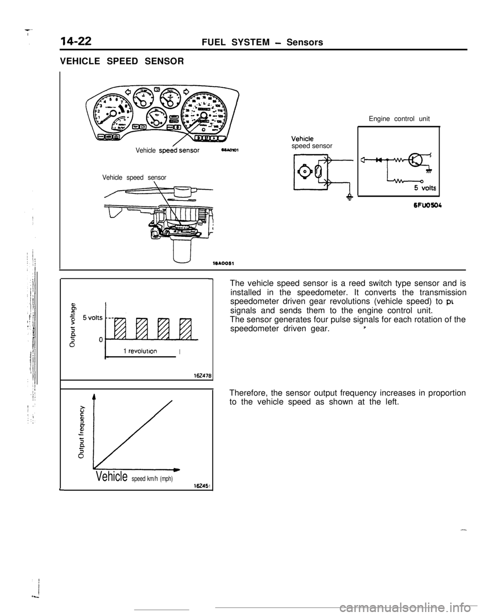
1Vehicle speed km/h (mph)The vehicle speed sensor is a reed switch type sensor and is
installed in the speedometer. It converts the transmission
speedometer driven gear revolutions (vehicle speed) to
ptsignals and sends them to the engine control unit.
The sensor generates four pulse signals for each rotation of the
speedometer driven gear.
5Therefore, the sensor output frequency increases in proportion
to the vehicle speed as shown at the left.
-
Page 192 of 391
PROPELLER SHAFT -General Information / Liibro Joint16-3
SPEClFlCATlONSterns
‘repeller shaft
Type
Length
x O.D.mm (in.)
Front
Center
RearUniversal joint
Type
No. 1 (front)
No. 2 (center front)
No. 3 (center rear) [Ldbro joint]
No. 4 (rear)Cross type universal joint bearing
Cross type universal joint journal O.D.mm (in.)Constant velocity joint type
Constant velocity joint size O.D.mm (in.)
NOTE
Specifications
4 joint propeller shaft707
x 50.8 (27.8 x 2.00)647.5 x 50.8 (25.5 x
2.00)530.5 x 50.8 (20.9 x
2.00)
Cross type
Cross type
CV type
Cross type
Needle roller bearing (oilless type)
14.689 i.5783)
LGbro joint (oilless type)94
(3.7)The propeller shaft length is the length between the centers of the joints.
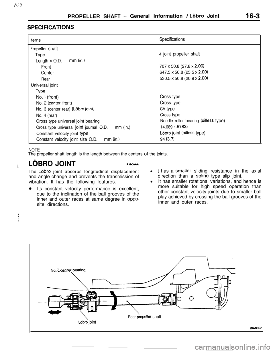
LOBRO JOINTRl6CMAThe
L6bro joint absorbs longitudinal displacement
and angle change and prevents the transmission of
vibration. It has the following features.
0Its constant velocity performance is excellent,
due to the inclination of the ball grooves of the
inner and outer races at same degree in
oppo-site directions.l It has a smaller sliding resistance in the axial
direction than a spline type slip joint.
l
It has smaller rotational variations, and hence is
more suitable for high speed operation than
other constant velocity joints due to smaller ball
play achieved by crossing the ball grooves of the
inner and outer races.
Nn 7 center bearina
\Lejbro joint
Rear &opeller shaft
lOAooo2
Page 193 of 391
- --- -._ -...PROPELLER SHAFT
- LBbro Joint / Center Bearing
groove
Inner race
ball groove
Outer race
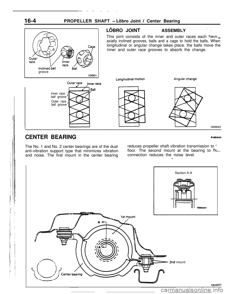
ball grooveLGBRO
JOltiT ASSEMBLY ’ IThis joint consists of the inner and outer races each havir,,
axially inclined grooves, balls and a cage to hold the balls. Whenlongitudinal or angular change takes place. the balls move the
inner and outer race grooves to absorb the change.
CENTER BEARINGRlSDWThe No. 1 and No. 2 center bearings are of the dualreduces propeller shaft vibration transmission to ’
anti-vibration support type that minimizes vibrationfloor. The second mount at the bearing to
flo,,and noise. The first mount in the center bearingconnection reduces the noise level.
*Section A-A
2nd mount
1ouooo3
Page 199 of 391
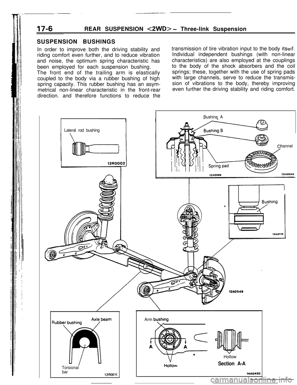
17-6REAR SUSPENSION <2WD> - Three-link Suspension
SUSPENSION BUSHINGS
In order to improve both the driving stability and
riding comfort even further, and to reduce vibration
and noise, the optimum spring characteristic has
been employed for each suspension bushing.
The front end of the trailing arm is elastically
coupled to the body via a rubber bushing of high
spring capacity. This rubber bushing has an asym-
metrical non-linear characteristic in the front-rear
direction. and therefore functions to reduce thetransmission of tire vibration input to the body itself.
Individual independent bushings (with non-linear
characteristics) are also employed at the couplings
to the body of the shock absorbers and the coil
springs; these, together with the use of spring pads
with large channels, serve to reduce the transmis-
sion of vibrations to the body, thereby improving
even further the driving stability and riding comfort.
Lateral rod bushingBushina A
hannel
f3ub
Torsional
barArm
bushmg\/HollowHoilow
Section A-A
Page 214 of 391

.-. --POWER STEERING
- Power Steering Gear Box Construction19-5
-POWER STEERING GEAR BOX CONSTRUCTIONRlsJLIIUB,
ne steering gear box is of the rack and pinion type
with a built-in hydraulic control unit which uses a
compact and highly reliable rotary valve.The steering gear box, in the same way as the
manual steering gear box, is installed to the body by
way of the mounting rubber in order to reduce the
transmission of vibrations.
Section A-A
Beari
1-$ysy input shaft
To oilreservoir
LFrom oil
I’Rotary valve
Yoke spring
13A0257
Section B-B
From oil pumpTo oil reservoir
To cylinder tubeleft chamber
To cylinder tube
13A0077right chamber