window MITSUBISHI ECLIPSE 1990 Service Manual
[x] Cancel search | Manufacturer: MITSUBISHI, Model Year: 1990, Model line: ECLIPSE, Model: MITSUBISHI ECLIPSE 1990Pages: 391, PDF Size: 15.27 MB
Page 55 of 391
ELECTRICAL - Fuses8-3q
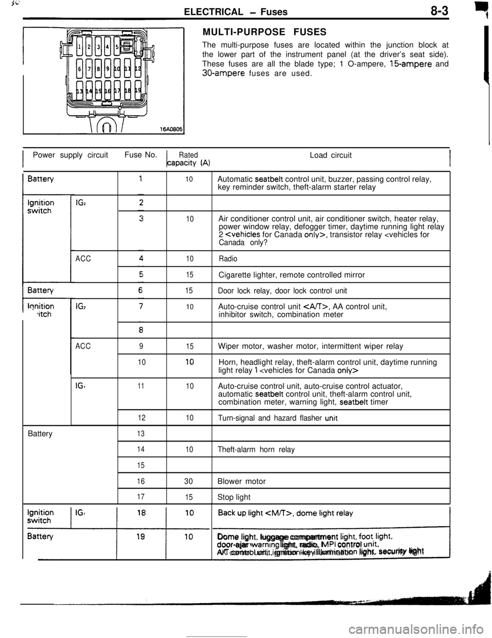
rMULTI-PURPOSE FUSES
The multi-purpose fuses are located within the junction block at
the lower part of the instrument panel (at the driver’s seat side).
These fuses are all the blade type; 1 O-ampere, 15-ampere and
30-ampere fuses are used.
IPower supply circuitFuse No.
RatedLoad circuitapacity
(A)IBattery
t-lonition,itchBattery
IGz
ACC
IG,
10
10
10
15
15
10Automatic seatbelt control unit, buzzer, passing control relay,
key reminder switch, theft-alarm starter relay
Air conditioner control unit, air conditioner switch, heater relay,
power window relay, defogger timer, daytime running light relay
2
Door lock relay, door lock control unitAuto-cruise control unit
, AA control unit,
inhibitor switch, combination meter
ACC
IGI9
1011
12
1315
10
10
10Wiper motor, washer motor, intermittent wiper relay
Horn, headlight relay, theft-alarm control unit, daytime running
light relay
1
automatic seatbelt control unit, theft-alarm control unit,
combination meter, warning light, seatbelt timer
Turn-signal and hazard flasher u.nit
14
15
16
17
10Theft-alarm horn relay
30Blower motor
15Stop light
Back up light
CM/T>, dome light relay
!Dome light. luggage compartment
Irght, foot. Irght.door-ajar warntng light, radio, MPI control unrt.AK control unit, ignition key illumination light.security lightI
Page 65 of 391
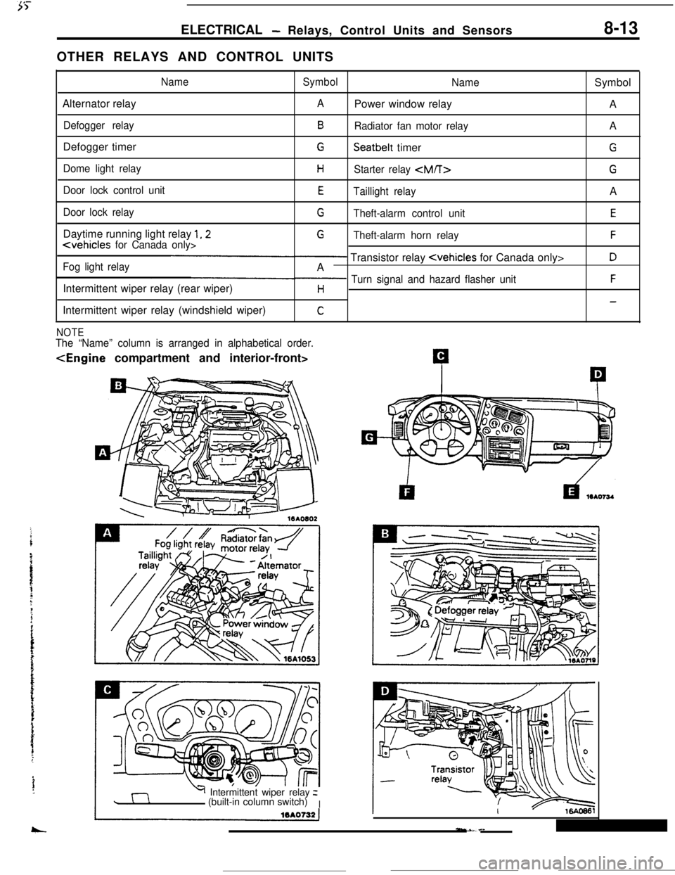
ELECTRICAL- Relays, Control Units and Sensors8-13OTHER RELAYS AND CONTROL UNITS
NameSymbol
NameSymbol
Alternator relay
APower window relay
A
Defogger relayBRadiator fan motor relayA
Defogger timer
GSeatbelt timerG
Dome light relayHStarter relay
Door lock control unitETaillight relayA
Door lock relayGTheft-alarm control unitEDaytime running light relay
1,2G
Fog light relay- Transistor relay
Intermittent wiper relay (rear wiper)
p Turn signal and hazard flasher unitFH-Intermittent wiper relay (windshield wiper)
C
NOTEThe “Name” column is arranged in alphabetical order.
Y Intermittent wiper relayz
(built-in column switch)
I
Page 85 of 391
ELECTRICAL - Theft-alarm System8-33ARMING THE SYSTEM
After the following procedures have been completed, the SECURITY light illuminates for about 20 seconds,
and when illumination stops, the system is armed.
(1) Pull out the ignition key from the key cylinder.
(2) Open a door. (The other door is closed.)
(3) Lock the door with the key or the
keyless-locking method.
(The central door locking system will then function to lock all doors.)
NOTE(1) The system is set regardless of whether the hood and liftgate are open or
closed, and is armed as
soon as the light goes out.
(2) Even after the system has been armed, if the key is used to open the liftgate, the system will not be
activated; when the liftgate is then
closed, moreover, the system will be armed.
DISARMING THE SYSTEM
(1) The system will be disarmed if the key is used to unlock a door.
(2) If the system is armed while the driver is still in the vehicle, the system can be disarmed by inserting the
ignition key and turning it to the ACC or ON position.
(3) If the door lock is unlocked while closing the door or the door is ajar.
(4) If the door is unfastened while the SECURITY light illuminates.
ACTIVATING THE ALARM
(1) if an attempt is made to open a door, the liftgate or the hood, without using the key, while the system is
armed, the horn will sound intermittently and the headlights will flash on and off for approximately
three,
minutes.Furthermore, the starter circuit is interrupted at this time also, making starting of the engine impossible.
(2) if a further attempt at *forcible entry is made after the first three-minute alarm has finished, the
three-minute alarm will be activated again.
DEACTIVATING THE ALARM
(1) To deactivate the alarm, insert the key into the door’s key cylinder and turn the key.
(2) The alarm is deactivated and the system is disarmed when the iiftgate is unlocked with the key.
CHECKING THE SYSTEM OPERATION
The activation/operation of the system can be checked by following the steps below.
(1) Turn the ignition key to the ON position and then use the power-window switch to fully open the window
at the driver’s seat side.
(2) Turn the ignition key to the LOCK position and then remove the key from the ignition.
(3) Open only the driver’s door, and close all the other doors, as well as the hood and the rear hatch.
(4) Lock the driver’s door by the key or the
keyless-locking method.
(5) All doors will then be
locked, and the SECURITY light (within the combination meter) will illuminate; check
to be sure that illumination stops in about 20 seconds.
(6) After about two seconds have passed after the SECURITY light illumination stopped, reach through the
window of the driver’s door, pull up the lock lever to unlock the door, and then open the door.
(7) Check to be sure that, when the door is opened, the horn starts sounding and the headlights flash on and
Off.
(8) To stop the alarm, insert the key into the door’s key cylinder and turn the key.
!?iEeck the alarm for the opening of the liftgate or hood open the liftgate (or the hood) by using the
remote liftgate release lever (or the hood release lever),
located at the driver’s seat side either before the
alarm is activated by the opening of a door, or after the finish of the first three-minute alarm.
Page 336 of 391
i73BODY
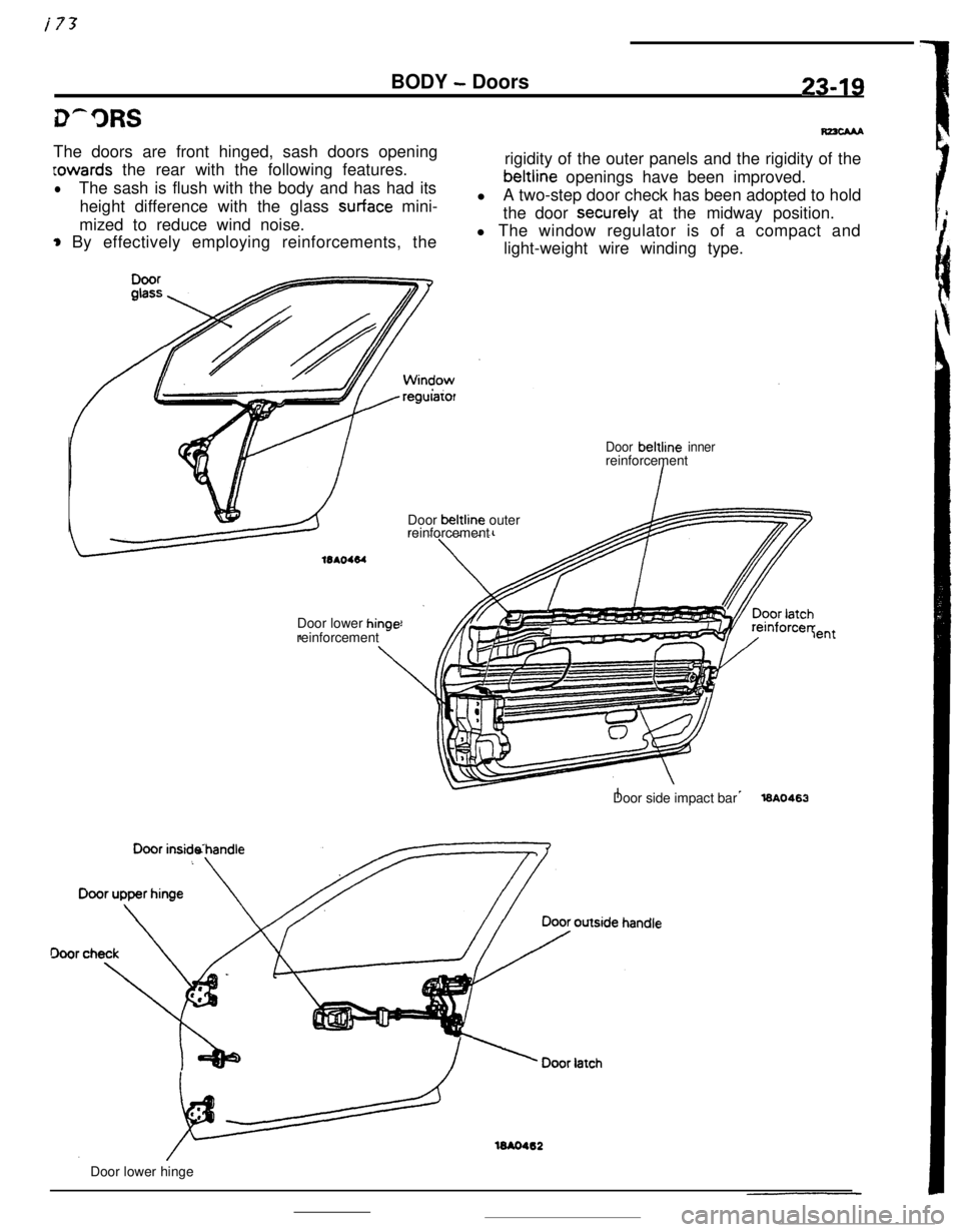
- Doors23-19The doors are front hinged, sash doors opening
Lowards the rear with the following features.
lThe sash is flush with the body and has had its
height difference with the glass
surface mini-
mized to reduce wind noise.
* By effectively employing reinforcements, the
regularorrigidity of the outer panels and the rigidity of thebeltline openings have been improved.
lA two-step door check has been adopted to hold
the door securely at the midway position.
l The window regulator is of a compact and
light-weight wire winding type.
Door beltline innerreinforcement
Door beltline outer
reinforcement
Door lower
hinr-reinforcement *-lentDoor side impact bar
l6A0463
16AO462Door lower hinge
Page 339 of 391
23-22BODY - Power Windows
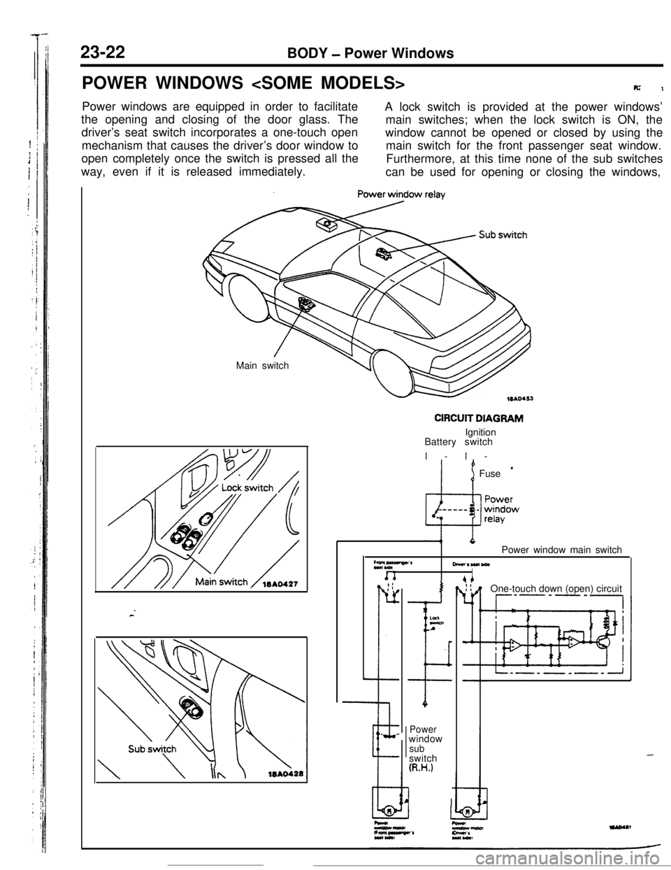
POWER WINDOWS
R’1Power windows are equipped in order to facilitate
A lock switch is provided at the power windows’
the opening and closing of the door glass. The
main switches; when the lock switch is ON, the
driver’s seat switch incorporates a one-touch open
mechanism that causes the driver’s door window towindow cannot be opened or closed by using the
main switch for the front passenger seat window.
open completely once the switch is pressed all the
way, even if it is released immediately.Furthermore, at this time none of the sub switches
can be used for opening or closing the windows,
Main switch
CIRCUIT DIAGRAMIgnition
Battery switch
l-l-
’ 1Fuse ’
Z*,“““”CrPower window main switch
-*W(WlI. _;:
r-
L
--e.
.
I
ELnA
I
Powerwindow
subswitch
(R.H.)
I IOne-touch down (open) circuit
--P’-‘-,
-
Page 340 of 391
BODY - Power Windows23-23
IBatterv
---IBatteryOPERATION OF THE POWER WINDOWS
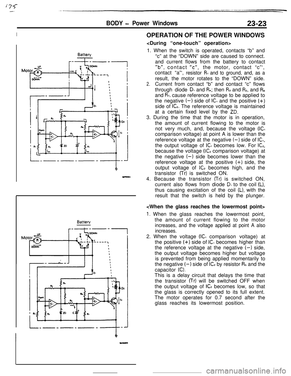
1. When the switch is operated, contacts “b” and
“c” at the “DOWN” side are caused to connect.
and current flows from the battery to contact
“b”, contact “c”,the motor, contact “c”‘,
contact “a”‘,
resistor R and to ground, and, as aresult, the motor rotates to the “DOWN” side.
2.Current from contact “b” and contact “c” flows
through diode
DI and R.; then I% and I%, and R,and
R7, cause reference voltage to be applied to
the negative
(-) side of IC and the positive (+)
side of
G. The reference voltage is maintained
at a certain fixed level by the
ZD.3. During the time that the motor is in operation,
the amount of current flowing to the motor is
not very much, and, because the voltage
(ICcomparison voltage) at point A is lower than the
reference voltage at the negative
(-) side of IC,,the output voltage of
IC becomes low. For G,because the voltage
(G comparison voltage) at
the negative
(-) side becomes lower than the
reference voltage at the positive (+) side, the
output voltage of
lC2 becomes high, and the
transistor
(Tr) is switched ON.
4. Because the transistor
(Tr) is switched ON,
current also flows from diode
D1 to the coil (L).thus causing excitation of the coil
IL), with the
result that the switch is held by the plunger.
1. When the glass reaches the lowermost point,
the amount of current flowing to the motor
increases, and the voltage applied at point A also
increases.2. When the voltage
(IC comparison voltage) at
the positive
(+) side of IC becomes higher than
the reference voltage at the negative
(-) side,
the output voltage becomes higher but voltage
is prevented from being applied momentarily to
the negative
I-) side of ICI by resistor R6 and the
capacitor
0.This is a delay circuit that delays the time that
the transistor
(Tr) will be switched OFF when
the output voltage of
IC, becomes low, so that
the glass is correctly opened to its full extent.
The motor operates for 0.7 second after the
glass reaches its lowermost position.
Page 341 of 391
23-24BODY - Power Windows / Bumpers
Batterv
r--+----
02’
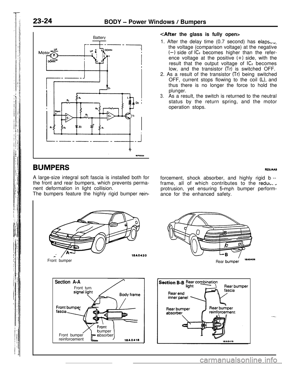
BUMPERSA large-size integral soft fascia is installed both for
the front and rear bumpers, which prevents perma-
nent deformation in light collision.
The bumpers feature the highly rigid bumper
rein-
18A0420
Section A-A
Front turn Front bumper
/Front bumperbumper
t Jabsorber
reinforcement18AOllB
1. After the delay time (0.7 second) has
claps,+,,,the voltage (comparison voltage) at the negative
(-1 side of IC2 becomes higher than the refer-
ence voltage at the positive
(+) side, with the
result that the output voltage of
ICI becomes
low, and the transistor
(Tr) is switched OFF.
2. As a result of the transistor
(Tr) being switched
OFF, current stops flowing to the coil
(L), and
thus there is no longer the force to hold the
plunger.
3.As a result, the switch is returned to the neutral
status by the return spring, and the motor
operation stops.
R22JMBforcement, shock absorber, and highly rigid
b --
frame, all of which contributes to the reduL.
aprotrusion, yet ensuring
5-mph bumper perform-
ance for the enhanced safety.
Rear bumpe:,.AOIOI
-
Page 367 of 391
L.
24-4HEATERS AND AIR CONDITIONING - General Information
’ /To side (door) window
(side defroster)
t4L\ m\vTofacearea
/(side ventilator)To windshiel
(defroster)
To side (door) window
(side defroster)
Blower switch
Toface area(side ventilator)
u rorootanTemperature control knob
, , , ,Air-selection lever
Air conditioner switch
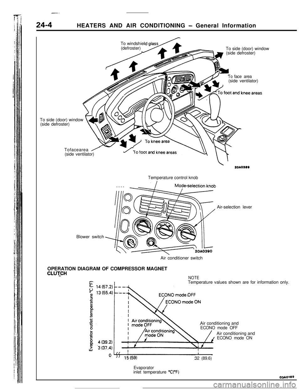
OPERATION DIAGRAM OF COMPRESSOR MAGNET
CLUTCHNOTETemperature values shown are for information only.
Air conditioning and
ECONO mode OFFAir conditioning and
ECONO mode ON
II
32 (89.6)
Evaporatorinlet temperature “WF)