light MITSUBISHI ECLIPSE 1991 Service Manual
[x] Cancel search | Manufacturer: MITSUBISHI, Model Year: 1991, Model line: ECLIPSE, Model: MITSUBISHI ECLIPSE 1991Pages: 1216, PDF Size: 67.42 MB
Page 14 of 1216
I4INTRODUCTION AND MASTER TROUBLESHOOTING - Precautions before Service
mm (In.1smo59
PARTSWhen replacing parts, use MOPAR genuine parts.
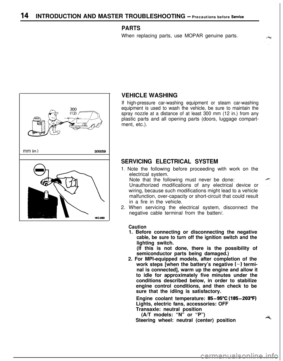
VEHICLE WASHING
If high-pressure car-washing equipment or steam car-washing
equipment is used to wash the vehicle, be sure to maintain the
spray nozzle at a distance of at least 300 mm (12 in.) from anyplastic parts and all opening parts (doors, luggage compart-
ment, etc.).
SERVICING ELECTRICAL SYSTEM
1. Note the following before proceeding with work on the
electrical system.
Note that the following must never be done:
Unauthorized modifications of any electrical device or
wiring, because such modifications might lead to a vehicle
malfunction, over-capacity or short-circuit that could result
in a fire in the vehicle.
2. When servicing the electrical system, disconnect the
negative cable terminal from the batten/.
Caution1. Before connecting or disconnecting the negative
cable, be sure to turn off the ignition switch and thelighting switch.
(If this is not done, there is the possibility of
semiconductor parts being damaged.)
2. For MPI-equipped models, after completion of the
work steps [when the battery’s negative
(-) termi-
nal is connected], warm up the engine and allow it
to idle for approximately five minutes under the
conditions described below, in order to stabilize
engine control conditions, and then check to be
sure that the idling is satisfactory.
Engine coolant temperature:
85-95°C (185-203°F)
Lights, electric fans, accessories: OFF
Transaxle: neutral position
(A/T models: “N” or “P”)
Steering wheel: neutral (center) position
Page 28 of 1216
28INTRODUCTION AND MASTER TROUBLESHOOTING - Tightening Torque
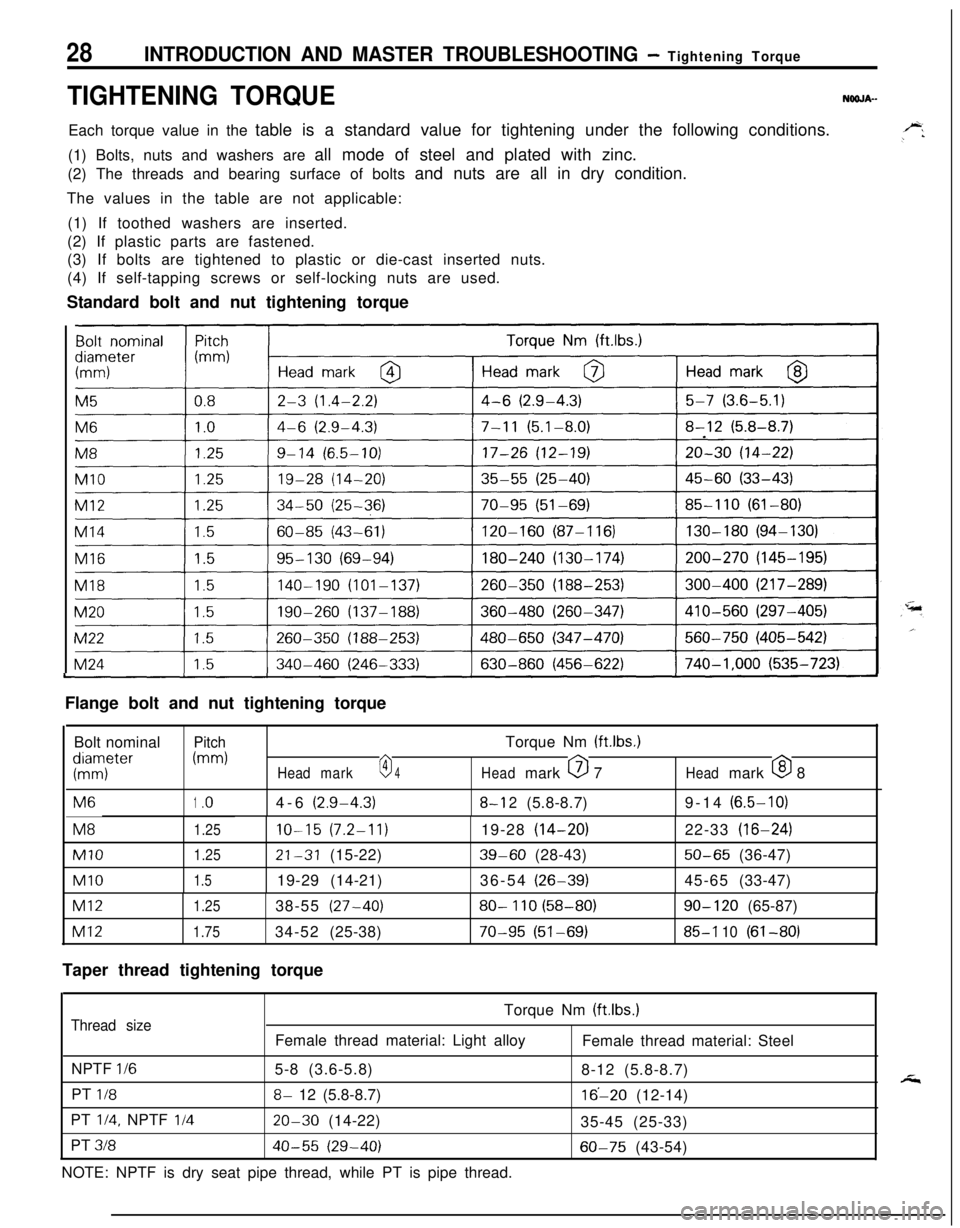
TIGHTENING TORQUENOOJA-Each torque value in the table is a standard value for tightening under the following conditions.
(1) Bolts, nuts and washers are all mode of steel and plated with zinc.
(2) The threads and bearing surface of bolts and nuts are all in dry condition.
The values in the table are not applicable:
(1) If toothed washers are inserted.
(2) If plastic parts are fastened.
(3) If bolts are tightened to plastic or die-cast inserted nuts.
(4) If self-tapping screws or self-locking nuts are used.
Standard bolt and nut tightening torque
I
I
ILFlange bolt and nut tightening torque
Bolt nominal
PitchTorque Nm (ftlbs.)
KTter
(mm)
Headmark0 4Headmark 0 7Headmark 0 8M6
1.o4-6(2.9-4.3)8-l 2(5.8-8.7)9-14(6.5-10)M8
1.25IO-15(7.2-11)19-28(14-20)22-33(16-24)
Ml01.2521-31(15-22)39-60(28-43)50-65(36-47)
Ml01.519-29(14-21)36-54(26-39)45-65(33-47)
Ml21.2538-55(27-40)80- 110 (58-80)90- 120(65-87)
Ml21.7534-52(25-38)70-95 (51-69)85-l 10(61-80)
Taper thread tightening torque
Torque Nm (ftlbs.)
Thread sizeFemale thread material: Light alloy
Female thread material: Steel
NPTF
l/65-8 (3.6-5.8)
8-12 (5.8-8.7)
PT
l/88- 12 (5.8-8.7)16’-20 (12-14)
PT
l/4, NPTF I/420-30 (14-22)
35-45 (25-33)
PT
31840-55 (29-40)60-75 (43-54)
NOTE: NPTF is dry seat pipe thread, while PT is pipe thread.
Page 47 of 1216
LUBRICATION AND MAINTENANCE - Maintenance Serviceo-13
OOAOlB6
13.BRAKE HOSES (Check for deteriorati.on or
leaks)NwBBnAs
Inspection of brake hoses and tubing should be included inall brake service operations.
The hoses should be checked for:
1. Correct length, severe surface cracking, pulling, scuf-
fing or worn spots. (If the fabric casing of the hoses is
exposed by cracks of abrasion in the rubber hose cover,
the hoses should be replaced. Eventual deterioration ofhose may occur with possible bursting failure.)
2. Faulty installation, casing twisting or interference with
wheel, tire of chassis.
14.BALL JOINT AND STEERING LINKAGE SEALS
(Inspect for grease leaks and damage)
NWSBJAb1. These components, which are permanently lubricated
at the factory, do not require periodic lubrication.
Damaged seals and boots should be replaced to
prevent leakage or contamination of the grease.
2. Inspect the dust cover and boots for proper sealing,
leakage and damage. Replace them if defective.
15.DRIVE SHAFT BOOTS (Inspect for grease leaksand damage)
NWSBJAc1. These components, which are permanently lubricated
at the factory, do not require periodic lubrication.
Damaged boots should be replaced to prevent leakage
or contamination of the grease.
2. Inspect the boots for proper sealing, leakage and
damage. Replace it if defective.
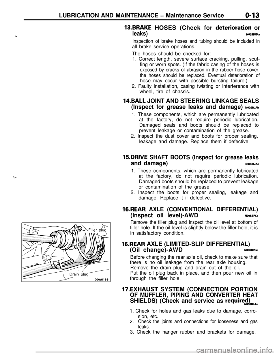
16.REAR AXLE (CONVENTIONAL DIFFERENTIAL)(Inspect oil level)-AWD
NWSBFCa
Remove the filler plug and inspect the oil level at bottom offiller hole. If the oil level is slightly below the filler hole, it is
in satisfactory condition.
16.REAR AXLE (LIMITED-SLIP DIFFERENTIAL)
(Oil change)-AWD
N66SBFCcBefore changing the rear axle oil, check to make sure that
there is no oil leakage from the rear axle housing.
Remove the drain plug and drain out of the oil.
Put the oil plug back in place, and then pour new oil in
through the filler hole.
17.EXHAUST SYSTEM (CONNECTION PORTION
OF MUFFLER, PIPING AND CONVERTER HEATSHIELDS) (Check and service as
require$dBu.
1. Check for holes and gas leaks due to damage, corro-
sion, etc.
2.Check the joints and connections for looseness and gas
leaks.3. Check the hanger rubber and brackets for damage.
Page 50 of 1216
2-2FRONT SUSPENSION - Specifications
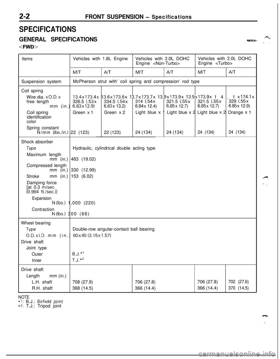
SPECIFICATIONS
GENERAL SPECIFICATIONSNOZCA-
ItemsVehicles with 1.8L EngineVehicles with 2.0L DOHCVehicles with 2.0L DOHC
Engine
MM/TAITMITNTSuspension systemMcPherson strut with’ coil spring and compression’ rod type
Coil spring
Wire dia.
x0.D. x13.4x173.4x 13.6x173.6x 13.7x173.7x 13.9x173.9x 13.9x173.9x 14.1 x174.1xfree length326.5 (.53x334.5 (.54x314 (.54x321.5 (.55x321.5 (.55x329 (.55x
mm (in.) 6.83x12.9)6.83x
13.2)6.84x 12.4)6.85x 12.7)6.85x 12.7)6.85x 12.9)Coil springGreen
x 1Green x 2Light blue x 1 Light blue x 2 Light blue x 2 Orange x 1
identification
colorSpring constant
N/mm
(IbsAn.) 22 (123)22 (123)24 (134)24 (134)24 (134)24 (134)Shock absorber
TypeHydraulic, cylindrical double acting type
Maximum length
mm (in.) 483 (19.02)
Compressed length
mm (in.) 330 (12.99)
Strokemm (in.) 153 (6.02)
Damping force
[at 0.3
m/set.
(0.984 ft./sec.)l
Expansion
N (Ibs.) 1,000 (220)
ContractionN (Ibs.) 300 (66)
Wheel bearing
TypeDouble-row angular-contact ball bearing
0.D.xl.D. mm (in.) 80x40 (3.15x1.57)
Drive shaft
Joint type
OuterB.J.“l
InnerT.J.“’Drive shaft
Lengthmm (in.)
L.H. shaft708 (27.9)706 (27.8)
R.H. shaft368 (14.5)366 (14.4)
NOTE*1: B.J.: Birfield joint*2: T.J.: Tripod joint706 (27.8)
702 (27.6)366 (14.4)
370 (14.5)
Page 71 of 1216
FRONT SUSPENSION - Drive Shaft2-23
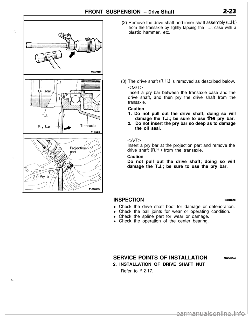
llE526(2) Remove the drive shaft and inner shaft
asSembly (L.H..)
from the transaxle by lightly tapping the T.J. case with a
plastic hammer, etc.
(3) The drive shaft
(R.H.) is removed as described below.
drive shaft, and then pry the drive shaft from the
transaxle.Caution
1. Do not pull out the drive shaft; doing so will
damage the T.J.; be sure to use the pry bar.
2.Do not insert the pry bar so deep as to damage
the oil seal.
Insert a pry bar at the projection part and remove the
drive shaft
(R.H.) from the transaxle.
Caution
Do not pull out the drive shaft; doing so will
damage the T.J.; be sure to use the pry bar.
INSPECTIONN02QCAEl Check the drive shaft boot for damage or deterioration.
l Check the ball joints for wear or operating condition.
l Check the spline part for wear or damage.
l Check the operation of the center bearing.
SERVICE POINTS OF INSTALLATION
2. INSTALLATION OF DRIVE SHAFT NUT
Refer to
P.2-17.
NOZQDAQ
Page 114 of 1216
3-12REAR AXLE - Drive ShaftTrailing arm
/c-4171
F
MB960931
1 lA0039Trailing arm
M B990799
11 A0040
7
llAO263
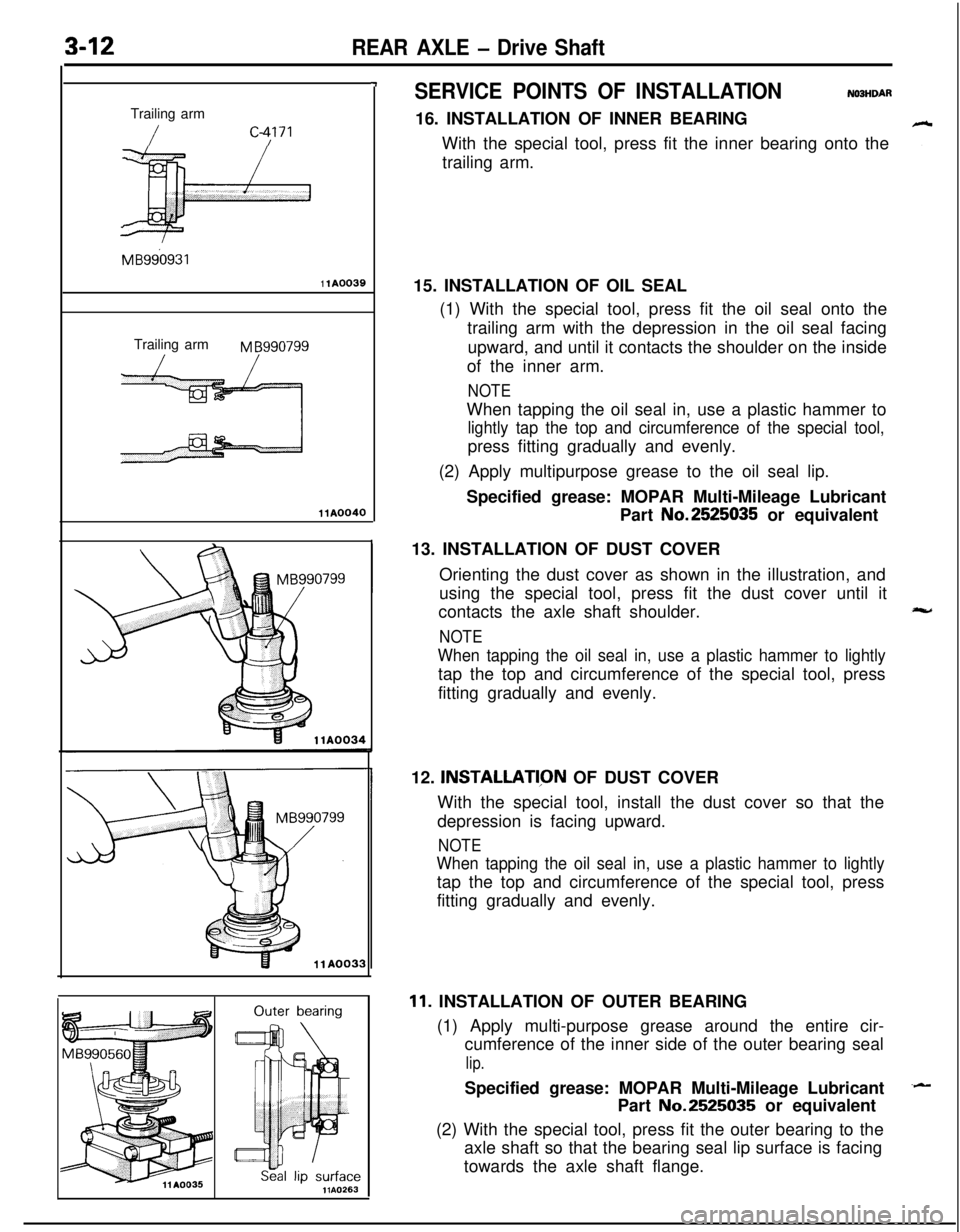
SERVICE POINTS OF INSTALLATIONN03HDAR16. INSTALLATION OF INNER BEARING
With the special tool, press fit the inner bearing onto the
trailing arm.
15. INSTALLATION OF OIL SEAL
(1) With the special tool, press fit the oil seal onto the
trailing arm with the depression in the oil seal facing
upward, and until it contacts the shoulder on the inside
of the inner arm.
NOTEWhen tapping the oil seal in, use a plastic hammer to
lightly tap the top and circumference of the special tool,press fitting gradually and evenly.
(2) Apply multipurpose grease to the oil seal lip.
Specified grease: MOPAR Multi-Mileage Lubricant
Part No.2525035 or equivalent
13. INSTALLATION OF DUST COVER
Orienting the dust cover as shown in the illustration, and
using the special tool, press fit the dust cover until it
contacts the axle shaft shoulder.
NOTE
When tapping the oil seal in, use a plastic hammer to lightlytap the top and circumference of the special tool, press
fitting gradually and evenly.
12.
INSTALLATl,ON OF DUST COVER
With the special tool, install the dust cover so that the
depression is facing upward.
NOTE
When tapping the oil seal in, use a plastic hammer to lightlytap the top and circumference of the special tool, press
fitting gradually and evenly.
11. INSTALLATION OF OUTER BEARING
(1) Apply multi-purpose grease around the entire cir-
cumference of the inner side of the outer bearing seal
lip.Specified grease: MOPAR Multi-Mileage Lubricant
Part No.2525035 or equivalent
(2) With the special tool, press fit the outer bearing to the
axle shaft so that the bearing seal lip surface is facing
towards the axle shaft flange.
Page 149 of 1216

BRAKES - Anti-lock Braking System Troubleshooting5-9
ANTI-LOCK BRAKING SYSTEM
-- TROUBLESHOOTINGNO!JEBAE
PARTICULAR CHARACTERISTICS OF
THE ANTI-LOCK BRAKING SYSTEMModels equipped with the anti-lock braking system
(A.B.S.) may exhibit one or more of the following
characteristics from time to time, but none of these
is abnormal.
(1) A pulsing feeling in the brake pedal, or vibration
of the body or the steering wheel, when the
anti-lock braking system is activated by sudden
braking or by braking on a slippery road surface.Actually, this phenomenon is an indication that
the anti-lock braking system is functioning nor-
mally.(2) When the vehicle speed reaches approximately
6 km/h (4 mph) after the engine is started and
the vehicle starts off (for the first time), a
whining motor noise may be heard from the
engine compartment if the vehicle is traveling in
a quiet place, but this noise is simply the result
of a self-check being made of the anti-lock
braking system operation.
TROUBLESHOOTING METHODSProblems related to the anti-lock braking system
(A.B.S.) can be classified into two general categor-
ies: problems in the electrical system and those in
the hydraulic system.For problems in the electrical system, the
self-diagnosis function is built into the electronic control
unit (E.C.U.) causing the A.B.S. warning light to
illuminate as a warning to the driver.
Problems in the hydraulic system (poor braking,
etc.) can be located in the same way as for ordinary
brakes. There is, however, the necessity to check todetermine whether the problem is related to ordin-
ary brake components or to the components relatedto the A.B.S.
HOW TO USE THE TROUBLESHOOTING
FLOW CHART(1) Using the flow chart, check the ABS warning
light light-up sequence and check the condition
of braking operation.
(2) Following the check chart listed in the remedy
column, perform the checks. There are [Explana-tion] and [Hint] in each check chart. Refer to
them when troubleshooting.
NOTEECU: Electronic control unit
HU: Hydraulic unit
MUT: Multi-use tester
Page 150 of 1216
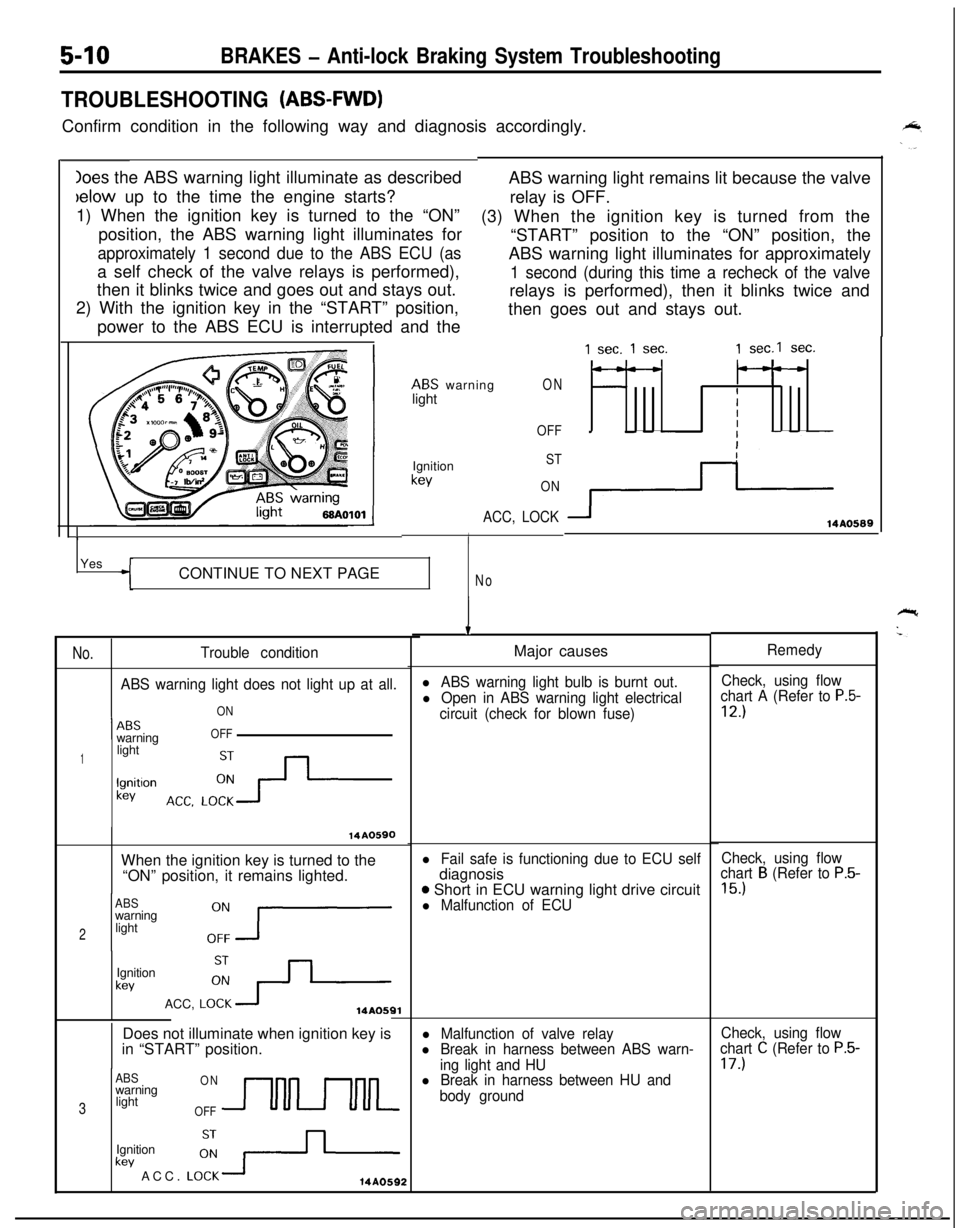
Ioes the ABS warning light illuminate as describedbelow up to the time the engine starts?
1) When the ignition key is turned to the “ON”
position, the ABS warning light illuminates for
approximately 1 second due to the ABS ECU (asa self check of the valve relays is performed),
then it blinks twice and goes out and stays out.
2) With the ignition key in the “START” position,
power to the ABS ECU is interrupted and the
5-10BRAKES - Anti-lock Braking System Troubleshooting
TROUBLESHOOTING (ABS-FWD)Confirm condition in the following way and diagnosis accordingly.
ABS warning light remains lit because the valve
relay is OFF.
(3) When the ignition key is turned from the
“START” position to the “ON” position, the
ABS warning light illuminates for approximately
1 second (during this time a recheck of the valverelays is performed), then it blinks twice and
then goes out and stays out.
ABS warning
lightON
OFF
1Ignition
kev
ST
ON
ACC, LOCK
IYes
CONTINUE TO NEXT PAGE
No
No.Trouble condition
ABS warning light does not light up at all.
ON
1 --ABSwarningOFF
1lightlgnitlon
kev
14A0590When the ignition key is turned to the
“ON” position, it remains lighted.
ABSwarning
2light
Ignition
kevACC,
LO:+14AOSQlDoes not illuminate when ignition key is
in “START” position.
ABSONwarning
3lightOFFUULkev ACC.
LO:-+-Ignition14A0592
1 sec. 1 sec.1 sec.1 sec.
---
IIII
3114AO589
IMajor causes
l ABS warning light bulb is burnt out.Check, using flow
l Open in ABS warning light electricalchart A (Refer to P.5-
circuit (check for blown fuse)12.)
l Fail safe is functioning due to ECU selfdiagnosis
o Short in ECU warning light drive circuitl Malfunction of ECU
l Malfunction of valve relayl Break in harness between ABS warn-
ing light and HU
l Break in harness between HU and
body groundRemedy
Check, using flow
chart
B (Refer to P.5-
15.)
Check, using flow
chart C (Refer to P.5-17.)
Page 151 of 1216
BRAKES - Anti-lock Braking System Troubleshooting5-14
./
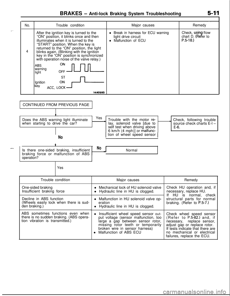
No.Trouble conditionMajor causesRemedyAfter the ignition key is turned to the
l Break in harness for ECU warningCheck, usinflow
“ON” position, it blinks once and then
light drive circuit
chart D. (Re er to9illuminates when it is turned to the
l Malfunction of ECUP.5-18.)“START” position. When the key is
4returned to the “ON” position, the light
blinks again. (Blinking with the ignition
key in the “ON” position is synchronized
with operation noise of the valve relay.)
ABSwarninglighto:-
Ignition
keyACC. LCi+-
14*0593CONTINUED FROM PREVIOUS PAGE
Does the ABS warning light illuminate
when starting to drive the car?
Yes~ Trouble with the motor re-lay, solenoid valve [due toL Check, following trouble
source check charts E-l -self test when driving above
E-6.6 km/h (4 mph)] or malfunc-
NoIs there one-sided braking, insufficient
braking force or malfunction of ABS
operation?
YesTrouble condition
Major causes
One-sided braking
Insufficient braking forcel Mechanical lock of HU solenoid valve
l Hydraulic line in HU is clogged.
Decline in ABS function
(Wheels easily lock when there is sud-
den braking.)
ABS sometimes functions even when
there is no sudden braking. (ABS opera-
tion vibration is transmitted.)
1 tion of wheel speed sensor 1
NoNormall Malfunction in HU solenoid valve op-
erationl Hydraulic line in HU is clogged.
l Insufficient wheel speed sensor out-
put voltage (sensor malfunction, too
large a gap between sensor rotor,
missing rotor teeth or temporarily
broken wire in sensor harness)
l Malfunction of ABS ECU
RemedyCheck HU operation and, if
necessary, replace HU.
If HU is normal, check
structural parts for normal
braking. (Refer to
P.5-7.)Check wheel speed sensor
(Refer to
P.5-82.) and, ifnecessary,replace sensor,
adjust gap or replace rotor.
If tests indicate that there are
no mechanical or electrical
failures, replace the ECU.
Page 152 of 1216
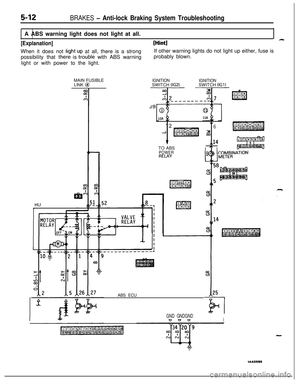
possibility that there is trouble with ABS warning
light or with power to the light.probably blown.
MAIN FUSIBLE
LINK @
5-12BRAKES - Anti-lock Braking System TroubleshootingA ABS warning light does not light at all.
I_
[Explanation][Hint]When it does not
liuht ULI at all, there is a strongIf other warning lights do not light up either, fuse is
IGNITIONSWITCH (IG2)IGNITIONSWITCH (IGl)
10A +,
“2.I6
-1z
v,,14TO ABS
I
” IPOWERIs&h ICOMBINAT~~N
ABS ECU
IGND GNDGNDv v vI
-14AO596