wheel bolts MITSUBISHI ECLIPSE 1991 Service Manual
[x] Cancel search | Manufacturer: MITSUBISHI, Model Year: 1991, Model line: ECLIPSE, Model: MITSUBISHI ECLIPSE 1991Pages: 1216, PDF Size: 67.42 MB
Page 31 of 1216
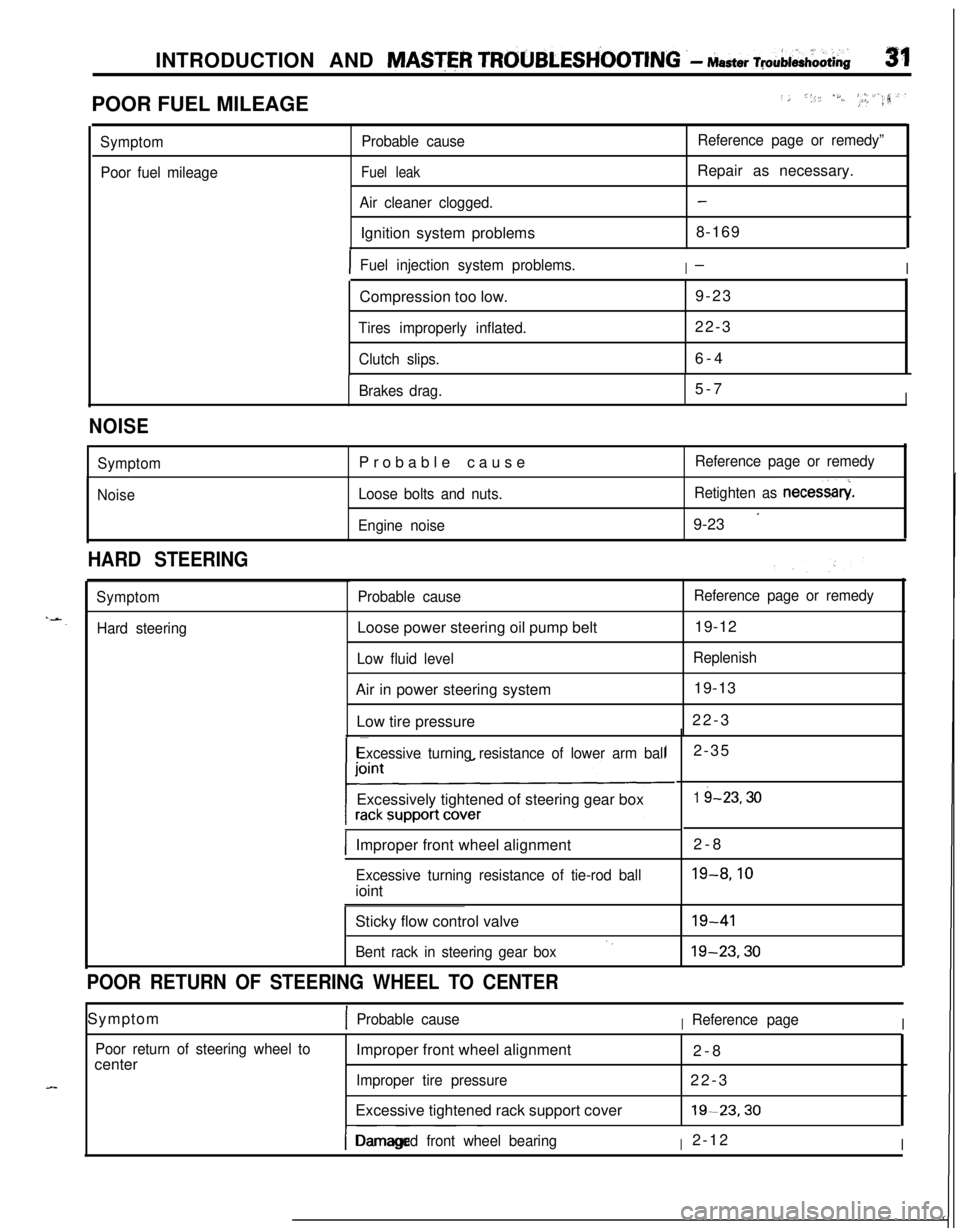
INTRODUCTION AND MASTER TROUBLESH’OOTING .- Master ~pAi&oOti~31POOR FUEL MILEAGE
../, *,, /S./..‘, _I, #_.a,‘.rr?
Symptom
Poor fuel mileageProbable cause
Fuel leak
Air cleaner clogged.Ignition system problems
Reference page or remedy”Repair as necessary.
-8-169
IFuel injection system problems.I-ICompression too low.9-23
Tires improperly inflated.22-3
Clutch slips.6-4
Brakes drag.5-7I
NOISE
Symptom
NoiseProbable cause
Loose bolts and nuts.
Engine noiseReference page or remedy
Retighten as necessary
9-23
’
HARD STEERING
Symptom
Hard steeringProbable causeLoose power steering oil pump belt
Low fluid levelAir in power steering system
Low tire pressure
Reference page or remedy19-12
Replenish19-13
22-3
Excessive turning resistance of lower arm ballExcessively tightened of steering gear box
IImproper front wheel alignment2-8
Excessive turning resistance of tie-rod ballioint2-35
1 i-23.30
19-8.10Sticky flow control valve
Bent rack in steering gear box‘.19-4119-23.30
POOR RETURN OF STEERING WHEEL TO CENTERSymptom
1Probable causeIReference pageI
Poor return of steering wheel tocenterImproper front wheel alignment
2-8
Improper tire pressure22-3
Excessive tightened rack support cover19-23.30
I-- ~~~Damaged front wheel bearingI2-12I
Page 53 of 1216
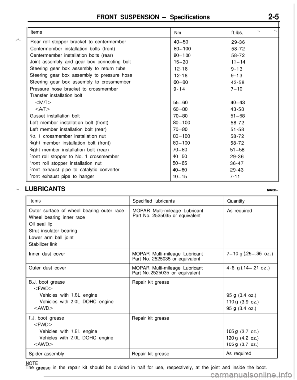
FRONT SUSPENSION - Specifications2-5Items
Rear roll stopper bracket to centermember
Centermember installation bolts (front)
Centermember installation bolts (rear)
Joint assembly and gear box connecting bolt
Steering gear box assembly to return tube
Steering gear box assembly to pressure hose
Steering gear box assembly to crossmember
Pressure hose bracket to crossmember
Transfer installation bolt
Nmftlbs. I’, ‘,
40-5029-36
80-10058-72
80-I 0058-72
15-20II-1412-18
9-13
12-189-13
60-8043-58
9-14
7-10
55-6040-43
Gusset installation bolt
70-8051-58Left member installation bolt (front)
80-10058-72
Left member installation bolt (rear)
70-8051-58
Vo. 1 crossmember installation nut80-10058-72qight member installation bolt (front)
80-10058-72?ight member installation bolt (rear)
70-8051-58
+ont roll stopper to No. 1 crossmember40-5029-36
?ont roll stopper installation nut50-6536-47
Iront exhaust pipe to catalytic converter40-6029-43
‘rant exhaust pipe to hangerIO-157-11
‘-. LUBRICANTSNO2CD--
ItemsSpecified lubricantsQuantity
Outer surface of wheel bearing outer race
MOPAR Multi-mileage LubricantAs required
Wheel bearing inner racePart No. 2525035 or equivalent
Oil seal lip
Strut insulator bearing
Lower arm ball joint
Stabilizer link
Inner dust coverMOPAR Multi-mileage Lubricant
Part No. 2525035 or equivalent
7-10 g (.25-.35 oz.)
Outer dust cover
MOPAR Multi-mileage Lubricant
Part
No.2525035 or equivalent4-6
g (.14-.21 oz.)
B.J. boot grease
Repair kit grease
1.8L engine
95 g (3.4 oz.)
Vehicles with
2.0L DOHC engine110 g (3.9 oz.)
T.J. boot grease
Repair kit grease
1.8L engine105 g (3.7 oz.)
Vehicles with
2.0L DOHC engine120 g (4.2 oz.)
Spider assemblyRepair kit greaseAs required
NOTEThe grease in the repair kit should be divided in half for use, respectively, at the joint and inside the boot.
Page 92 of 1216
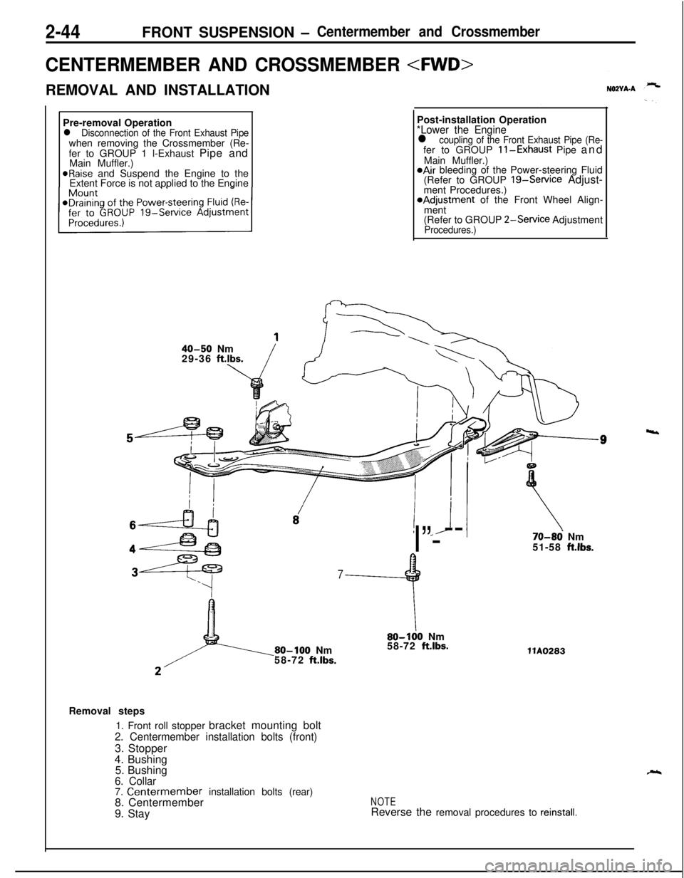
2-44FRONT SUSPENSION -Centermember and Crossmember
CENTERMEMBER AND CROSSMEMBER
REMOVAL AND INSTALLATION
Pre-removal Operation
l Disconnection of the Front Exhaust Pipewhen removing the Crossmember (Re-
fer to GROUP 1 l-Exhaust Pipe and
Main Muffler.)
@Raise and Suspend the Engine to the
Extent Force is not applied to the EnginePost-installation Operation
*Lower the Enginel coupling of the Front Exhaust Pipe (Re-fer to GROUP ll-Exhaust Pipe and
Main Muffler.)
@Air bleeding of the Power-steering Fluid
(Refer to GROUP 19-Service Adjust-
ment Procedures.)*Adjustment of the Front Wheel Align-
ment
(Refer to GROUP
2-Service AdjustmentProcedures.)
40-50 Nm
29-36 ft.lbs.
! *J
I”---
7
9
80-100 Nm
58-72 ft.lbs.
\80-100 Nm
58-72 ft.lbs.
70-86 Nm
51-58 ft.lbs.llA0283
Removal steps
1. Front roll stopper bracket mounting bolt
2. Centermember installation bolts (front)3. Stopper
4. Bushing
5. Bushing
6. Collar7. Centermember installation bolts (rear)
8. Centermember
9. StayNOTEReverse the removal procedures to reinstall.
4
Page 105 of 1216
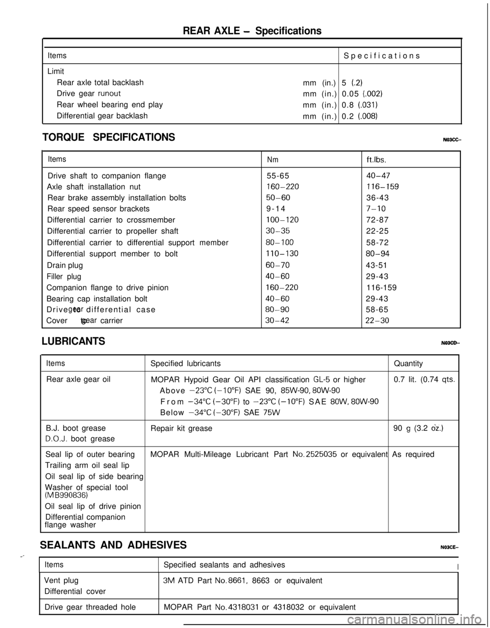
REAR AXLE - Specifications
ItemsLimit
Rear axle total backlash
Drive gear
runoutRear wheel bearing end play
Differential gear backlashSpecifications
mm (in.) 5
(.2)mm (in.) 0.05
(.002)mm (in.) 0.8
(.031)mm (in.) 0.2
(.008)
TORQUE SPECIFICATIONS
ItemsNmft.lbs.
Drive shaft to companion flange55-65
40-47Axle shaft installation nut
160-220116-159Rear brake assembly installation bolts
50-6036-43
Rear speed sensor brackets9-14
7-10Differential carrier to crossmember
100-12072-87
Differential carrier to propeller shaft
30-3522-25
Differential carrier to differential support
member80- 10058-72
Differential support member to bolt
110-13080-94Drain plug
60-7043-51
Filler plug40-6029-43
Companion flange to drive pinion
160-220116-159
Bearing cap installation bolt
40-6029-43
Drive to differential case
gear80-9058-65
Cover to carrier
gear30-4222-30
LUBRICANTS
ItemsRear axle gear oilSpecified lubricantsQuantity
MOPAR Hypoid Gear Oil API classification
GL-5 or higher0.7 lit. (0.74 qts.Above
-23°C (-10°F) SAE 90, 85W-90, 8OW-90From
-34°C (-30°F) to -23°C (-10°F) SAE 8OW, 8OW-90Below
-34°C (-30°F) SAE 75WB.J. boot grease
D.O.J. boot greaseRepair kit grease90
g (3.2 dz.)Seal lip of outer bearingMOPAR Multi-Mileage Lubricant Part No.2525035 or equivalent As required
Trailing arm oil seal lip
Oil seal lip of side bearing
Washer of special tool
(M B990836)Oil seal lip of drive pinion
Differential companion
flange washer
SEALANTS AND ADHESIVES
..-
ItemsSpecified sealants and adhesivesIVent plug
Differential cover3M ATD Part
No.8661, 8663 or equivalent
Drive gear threaded holeMOPAR Part
No.4318031 or 4318032 or equivalent
Page 109 of 1216
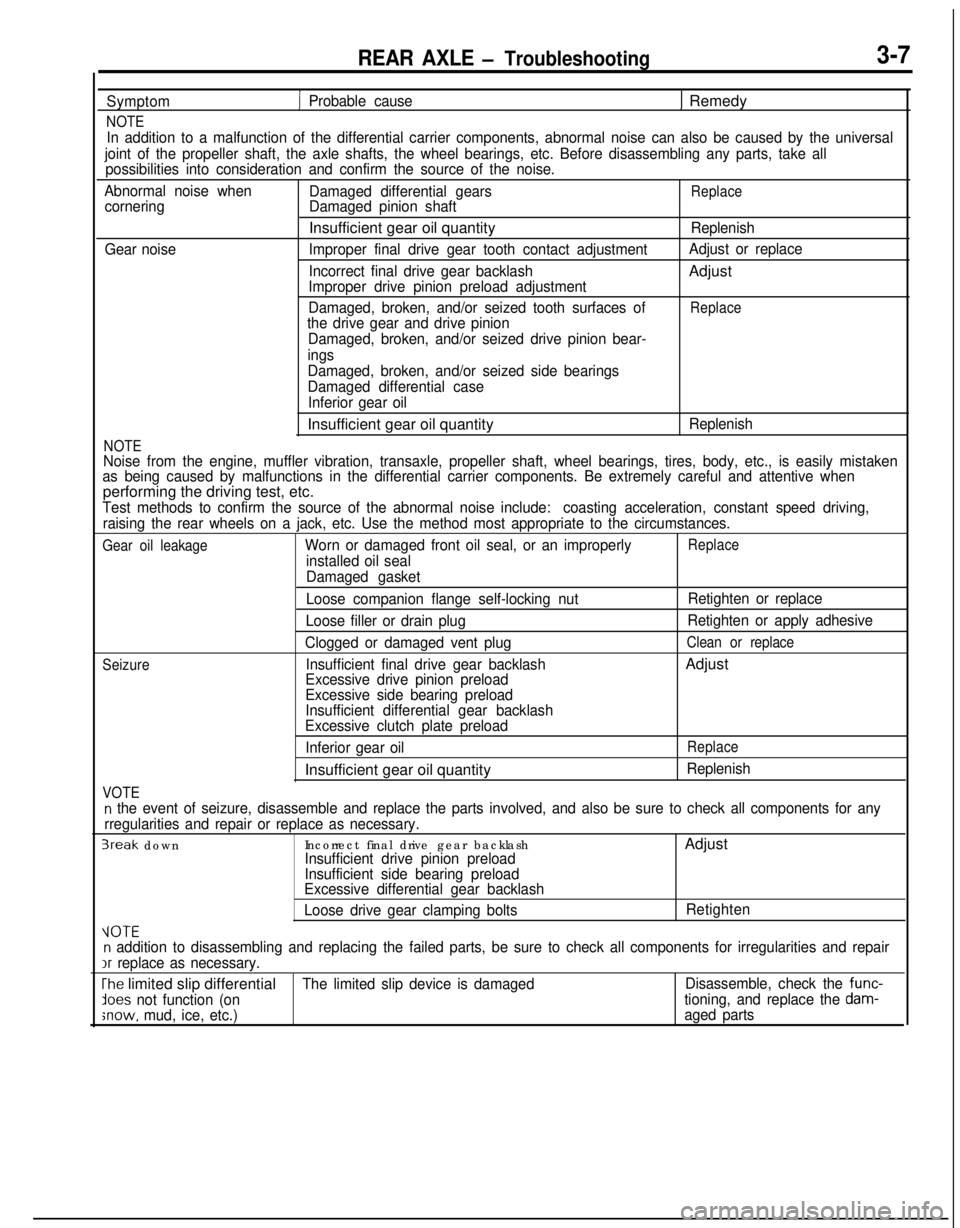
REAR AXLE - Troubleshooting3-7
Symptom
NOTE
1 Probable cause1 Remedy
In addition to a malfunction of the differential carrier components, abnormal noise can also be caused by the universal
joint of the propeller shaft, the axle shafts, the wheel bearings, etc. Before disassembling any parts, take all
possibilities into consideration and confirm the source of the noise.
Abnormal noise when
Damaged differential gears
ReplacecorneringDamaged pinion shaftInsufficient gear oil quantity
Replenish
Gear noiseImproper final drive gear tooth contact adjustmentAdjust or replace
Incorrect final drive gear backlashAdjust
Improper drive pinion preload adjustment
Damaged, broken, and/or seized tooth surfaces of
Replacethe drive gear and drive pinion
Damaged, broken, and/or seized drive pinion bear-
ings
NOTE
Damaged, broken, and/or seized side bearings
Damaged differential case
Inferior gear oilInsufficient gear oil quantity
Replenish
Noise from the engine, muffler vibration, transaxle, propeller shaft, wheel bearings, tires, body, etc., is easily mistaken
as being caused by malfunctions in the differential carrier components. Be extremely careful and attentive whenperforming the driving test, etc.
Test methods to confirm the source of the abnormal noise include:coasting acceleration, constant speed driving,
raising the rear wheels on a jack, etc. Use the method most appropriate to the circumstances.
Gear oil leakageWorn or damaged front oil seal, or an improperlyReplace
installed oil seal
Damaged gasket
Seizure
VOTE
Loose companion flange self-locking nut
Loose filler or drain plug
Clogged or damaged vent plug
Insufficient final drive gear backlash
Excessive drive pinion preload
Excessive side bearing preload
Insufficient differential gear backlash
Excessive clutch plate preload
Inferior gear oilInsufficient gear oil quantityRetighten or replace
Retighten or apply adhesive
Clean or replaceAdjust
Replace
Replenish
n the event of seizure, disassemble and replace the parts involved, and also be sure to check all components for any
rregularities and repair or replace as necessary.
3reak downIncorrect final drive gear backlashAdjustInsufficient drive pinion preload
Insufficient side bearing preload
Excessive differential gear backlash
Loose drive gear clamping boltsRetighten
VOTEn addition to disassembling and replacing the failed parts, be sure to check all components for irregularities and repairIr
replace as necessary.
The limited slip differentialThe limited slip device is damagedDisassemble, check the func-
lees not function (ontioning, and replace the dam-
;now, mud, ice, etc.)aged parts
Page 145 of 1216
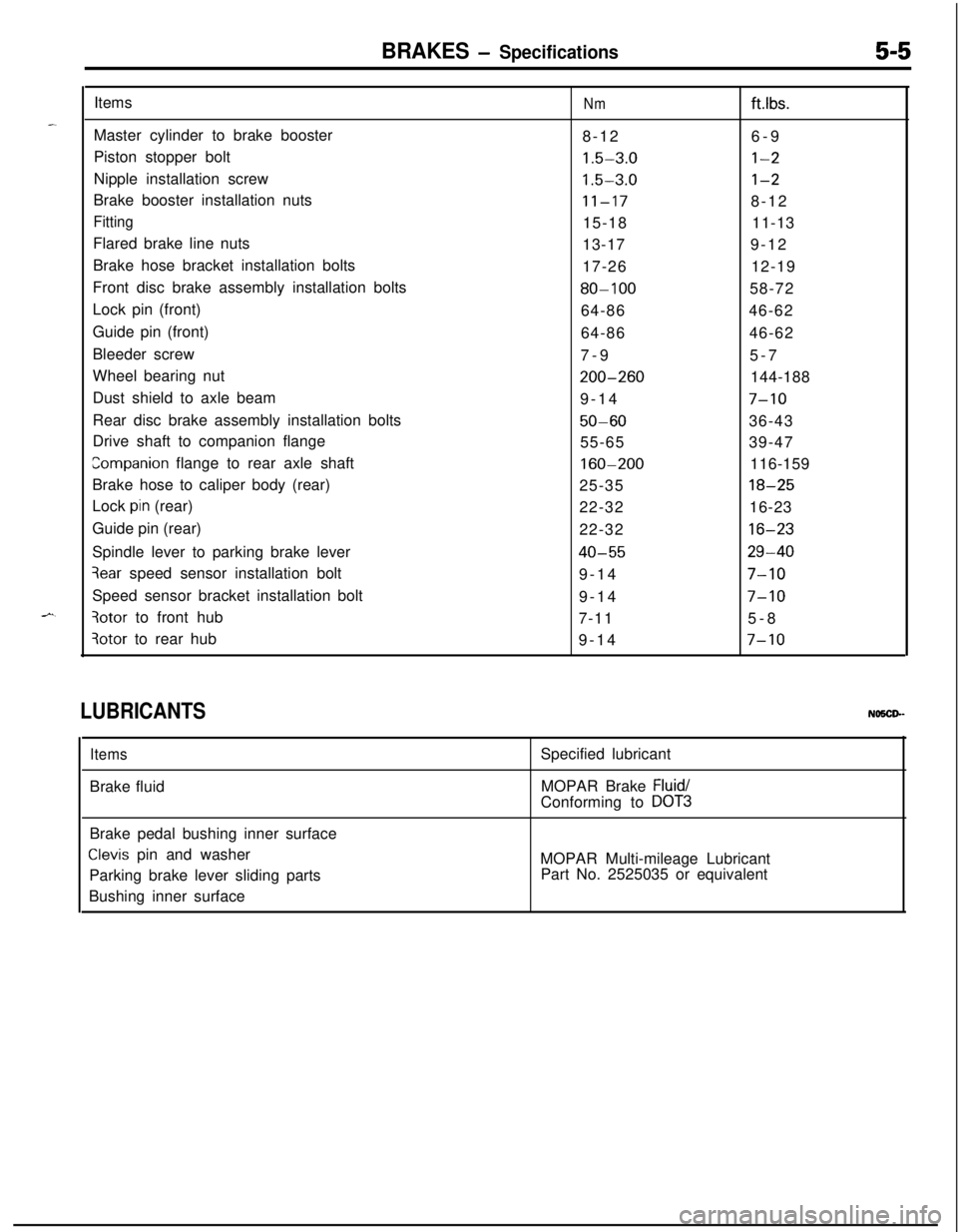
BRAKES - Specifications5-5Items
Nmftlbs.Master cylinder to brake booster
8-126-9
Piston stopper bolt
1.5-3.0l-2Nipple installation screw
1.5-3.0l-2Brake booster installation nuts
11-178-12
Fitting15-1811-13
Flared brake line nuts
13-179-12
Brake hose bracket installation bolts
17-2612-19
Front disc brake assembly installation bolts
80-10058-72
Lock pin (front)
64-8646-62
Guide pin (front)
64-8646-62
Bleeder screw
7-95-7
Wheel bearing nut
200-260144-188
Dust shield to axle beam
9-14
7-10Rear disc brake assembly installation bolts
50-6036-43
Drive shaft to companion flange
55-6539-47
companion flange to rear axle shaft160-200116-159
Brake hose to caliper body (rear)
25-35
18-25Lock
pin (rear)
22-3216-23
Guide pin (rear)
22-32
16-23Spindle lever to parking brake lever
40-5529-40
3ear speed sensor installation bolt
9-147-10Speed sensor bracket installation bolt
9-14
7-10
3otor to front hub
7-115-8
3otor to rear hub
9-147-10
LUBRICANTSNO5CP-
ItemsBrake fluidSpecified lubricant
MOPAR Brake
Fluid/Conforming to
DOT3Brake pedal bushing inner surface
Clevis pin and washer
Parking brake lever sliding parts
Bushing inner surfaceMOPAR Multi-mileage Lubricant
Part No. 2525035 or equivalent
Page 222 of 1216
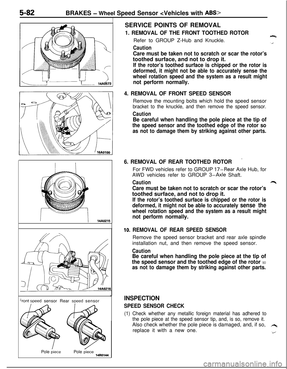
Care must be taken not to scratch or scar the rotor’stoothed surface, and not to drop it.
If the rotor’s toothed surface is chipped or the rotor is
deformed, it might not be able to accurately sense the
wheel rotation speed and the system as a result might
__ r-14A¬ perform normally.
4. REMOVAL OF FRONT SPEED SENSORRemove the mounting bolts which hold the speed sensor
bracket to the knuckle, and then remove the speed sensor.
Caution
5-82BRAKES - Wheel Speed Sensor
1. REMOVAL OF THE FRONT TOOTHED ROTOReRefer to GROUP Z-Hub and Knuckle.
Caution
Be careful when handling the pole piece at the tip of
the speed sensor and the toothed edge of the rotor so
as not to damage them by striking against other parts.
II14A0215
+ont weed sensor Rear meed sensor
Pole
piecePole piece14R0144
6. REMOVAL OF REAR TOOTHED ROTOR’For FWD vehicles refer to GROUP
17-Rear Axle Hub, for
AWD vehicles refer to GROUP
3-Axle Shaft.
Cautionr*
Care must be taken not to scratch or scar the rotor’stoothed surface, and not to drop it.
If the rotor’s toothed surface is chipped or the rotor is
deformed, it might not be able to accurately
sense the
wheel rotation speed and the system as a result might
not perform normally.
10. REMOVAL OF REAR SPEED SENSORRemove the speed sensor bracket and rear axle spindle
installation nut, and then remove the speed sensor.
Caution
Be careful when handling the pole piece at the tip of
the speed sensor and the toothed edge of the rotor
SO
as not to damage them by striking against other parts.
INSPECTION
SPEED SENSOR CHECK
(1) Check whether any metallic foreign material has adhered to
the pole piece at the speed sensor tip, and, is so, remove it.Also check whether the pole piece is damaged, and, if so,
hreplace it with a new one.
‘J
Page 247 of 1216
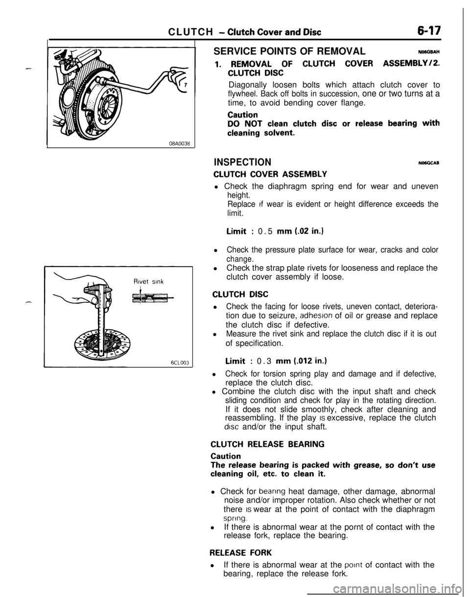
CLUTCH - Clutch Cover and Disc647
08A0038
6CLOO3SERVICE POINTS OF REMOVAL
NO6OSAH
1. REMOVAL OF CLUTCH COVER ASSEMBLY/P.
CLUTCH DISCDiagonally loosen bolts which attach clutch cover to
flywheel. Back off bolts in succession, one or two turns at atime, to avoid bending cover flange.
Caution
DO NOT clean clutch disc or release bearing with
cleaning solvent.
INSPECTIONNlNGCAB
CLUTCH COVER ASSEMBLYl Check the diaphragm spring end for wear and uneven
height.
Replace
If wear is evident or height difference exceeds the
limit.Limit
: 0.5 mm (.02 in.)l
Check the pressure plate surface for wear, cracks and color
change.lCheck the strap plate rivets for looseness and replace the
clutch cover assembly if loose.
CLUTCH DISCl
Check the facing for loose rivets, uneven contact, deteriora-tion due to seizure,
adhesron of oil or grease and replace
the clutch disc if defective.
l
Measure the rivet sink and replace the clutch disc if it is outof specification.Limit
: 0.3 mm (.012 in.)l
Check for torsion spring play and damage and if defective,replace the clutch disc.
l Combine the clutch disc with the input shaft and check
sliding condition and check for play in the rotating direction.If it does not slide smoothly, check after cleaning and
reassembling. If the play IS excessive, replace the clutch
drsc and/or the input shaft.
CLUTCH RELEASE BEARING
Caution
The release bearing is packed with grease, so don’t use
cleaning oil, etc. to clean it.l Check for
beanng heat damage, other damage, abnormal
noise and/or improper rotation. Also check whether or not
there IS wear at the point of contact with the diaphragm
spring.lIf there is abnormal wear at the pornt of contact with the
release fork, replace the bearing.
RELEASE FORKlIf there is abnormal wear at the
pornt of contact with the
bearing, replace the release fork.
Page 248 of 1216
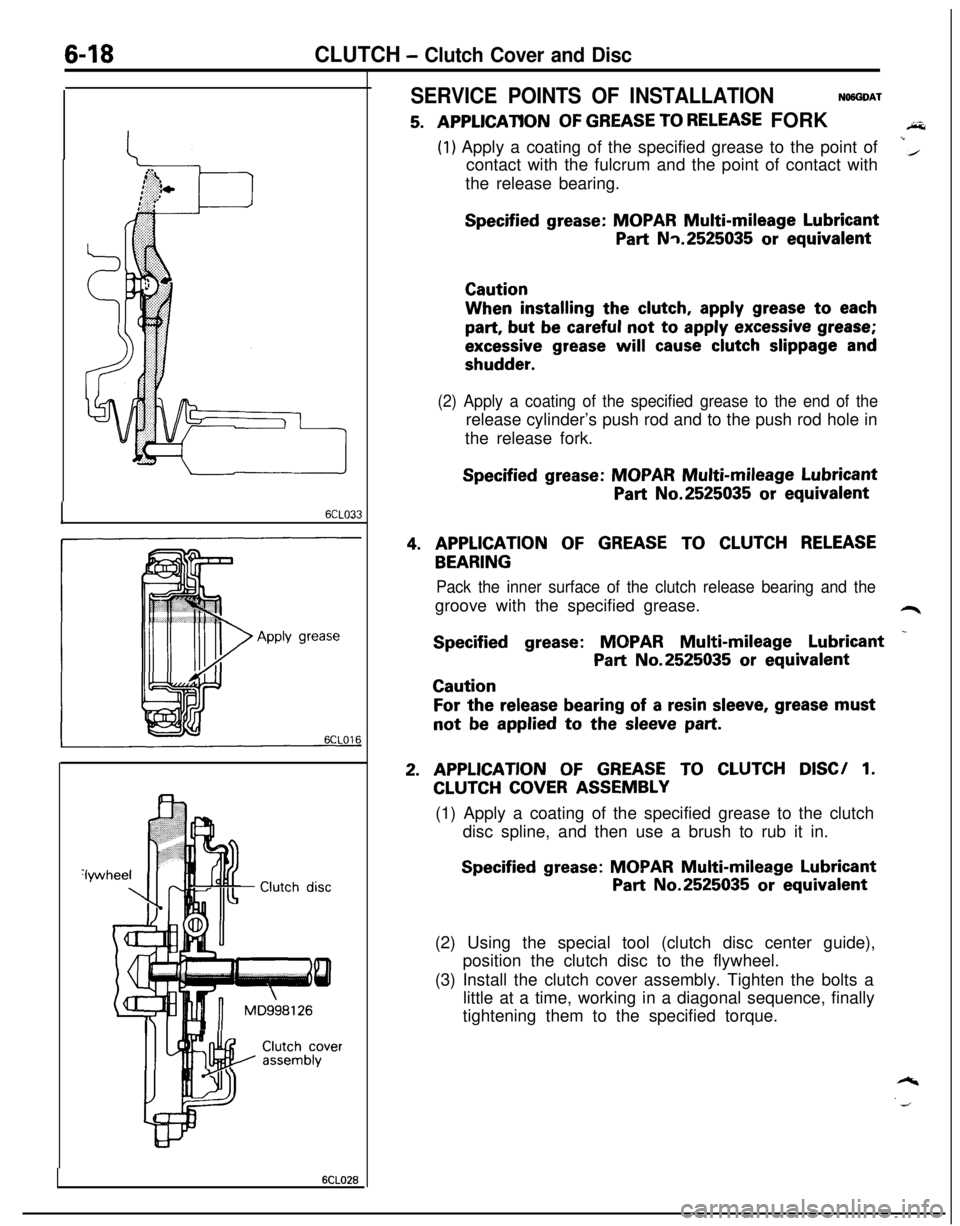
6-18CLUTCH - Clutch Cover and Disc
I6CLO33
Clutch disc
T& assemblyClutch cover
6CLO26
SERVICE POINTS OF INSTALLATIONNWGDAT
5. A,PPLlCATlONOF GREASE TO RELEASE FORKAi&
(1) Apply a coating of the specified grease to the point of
contact with the fulcrum and the point of contact withi(the release bearing.
Specified grease: MOPAR Multi-mileage Lubricant
Part Nq.2525035 or equivalentCautionWhen installing the
clutch, apply grease to each
part, but be careful not to apply excessive grease;
excessive grease will cause clutch slippage and
shudder.
(2) Apply a coating of the specified grease to the end of therelease cylinder’s push rod and to the push rod hole in
the release fork.
Specified grease: MOPAR Multi-mileage Lubricant
Part No.2525035 or equivalent
4. APPLICATION OF GREASE TO CLUTCH RELEASE
BEARING
Pack the inner surface of the clutch release bearing and thegroove with the specified grease.
L4r
Specified grease: MOPAR Multi-mileage Lubricant _
Part No.2525035 or equivalentCaution
For the release bearing of a resin sleeve, grease mustnot
be applied to the sleeve part.
2. APPLICATION OF GREASE TO CLUTCH DISC/ 1.
CLUTCH COVER ASSEMBLY
(1) Apply a coating of the specified grease to the clutch
disc spline, and then use a brush to rub it in.
Specified grease: MOPAR Multi-mileage Lubricant
Part No.2525035 or equivalent
(2) Using the special tool (clutch disc center guide),
position the clutch disc to the flywheel.
(3) Install the clutch cover assembly. Tighten the bolts a
little at a time, working in a diagonal sequence, finally
tightening them to the specified torque.
Page 302 of 1216
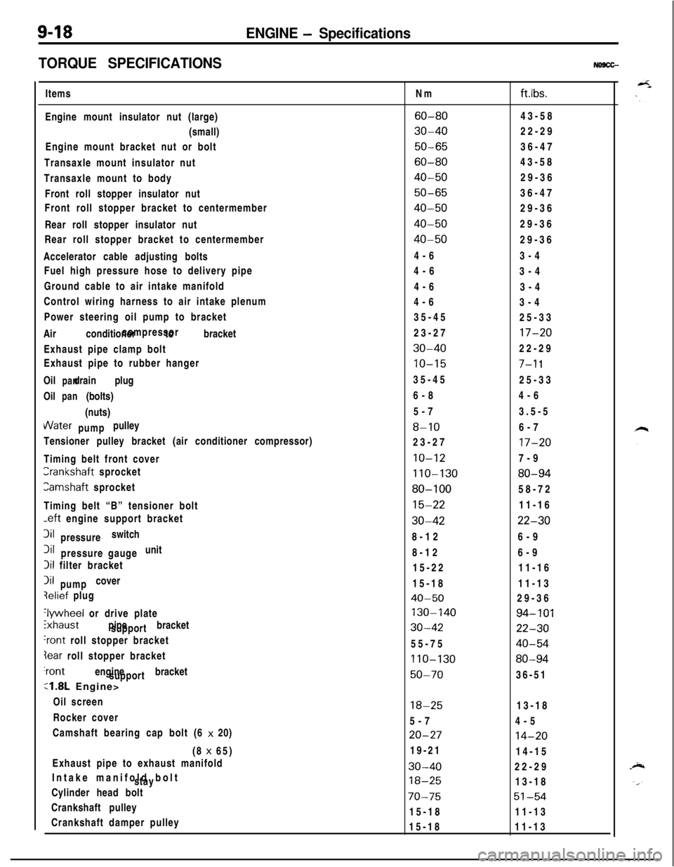
9-18ENGINE - Specifications
TORQUE SPECIFICATIONS
NO9CG-Items
Engine mount insulator nut (large)
(small)
Engine mount bracket nut or bolt
Transaxle mount insulator nut
Transaxle mount to body
Front roll stopper insulator nut
Front roll stopper bracket to centermember
Rear roll stopper insulator nut
Rear roll stopper bracket to centermember
Accelerator cable adjusting bolts
Fuel high pressure hose to delivery pipe
Ground cable to air intake manifold
Control wiring harness to air intake plenum
Power steering oil pump to bracket
Air conditioner to bracketcompressor
Exhaust pipe clamp bolt
Exhaust pipe to rubber hanger
Oil drain plug
panOil (bolts)
pan(nuts)VVater pulley
pump
Tensioner pulley bracket (air conditioner compressor)
Timing belt front coverCrankshaft sprocket
Camshaft sprocket
Timing belt “B” tensioner bolt
-eft engine support bracket3il switch
pressure3il unit
pressure gauge
Iii filter bracket
Iii cover
pumpqelief plug
‘lywheel or drive plate
ixhaust pipe bracket
support
‘rant roll stopper bracket
Iear roll stopper bracket‘rant engine bracket
support
:1.8L Engine>
Oil screen
Rocker cover
Camshaft bearing cap bolt (6 x 20)
(8 x 65)
Exhaust pipe to exhaust manifold
Intake manifold bolt
stay
Cylinder head bolt
Crankshaft pulley
Crankshaft damper pulleyNm
ftlbs.
60-8043-58
30-4022-29
50-6536-47
60-8043-58
40-5029-36
50-6536-47
40-5029-36
40-5029-36
40-5029-36
4-63-4
4-6
3-4
4-6
3-4
4-6
3-4
35-45
25-33
23-27
17-20
30-4022-29
10-157-l 135-45
25-33
6-84-6
5-73.5-5
8-106-7
23-27
17-20
10-127-9
110-13080-94
80-10058-72
15-2211-16
30-4222-308-126-9
8-126-9
15-2211-16
15-1811-13
40-5029-36
130-14094-101
30-4222-3055-75
40-54
110-13080-94
50-7036-51
18-2513-18
5-74-5
20-2714-2019-21
14-15
30-4022-29
18-2513-18
70-7551-5415-1811-13
15-1811-13