belt MITSUBISHI ECLIPSE 1991 Owners Manual
[x] Cancel search | Manufacturer: MITSUBISHI, Model Year: 1991, Model line: ECLIPSE, Model: MITSUBISHI ECLIPSE 1991Pages: 1216, PDF Size: 67.42 MB
Page 1068 of 1216
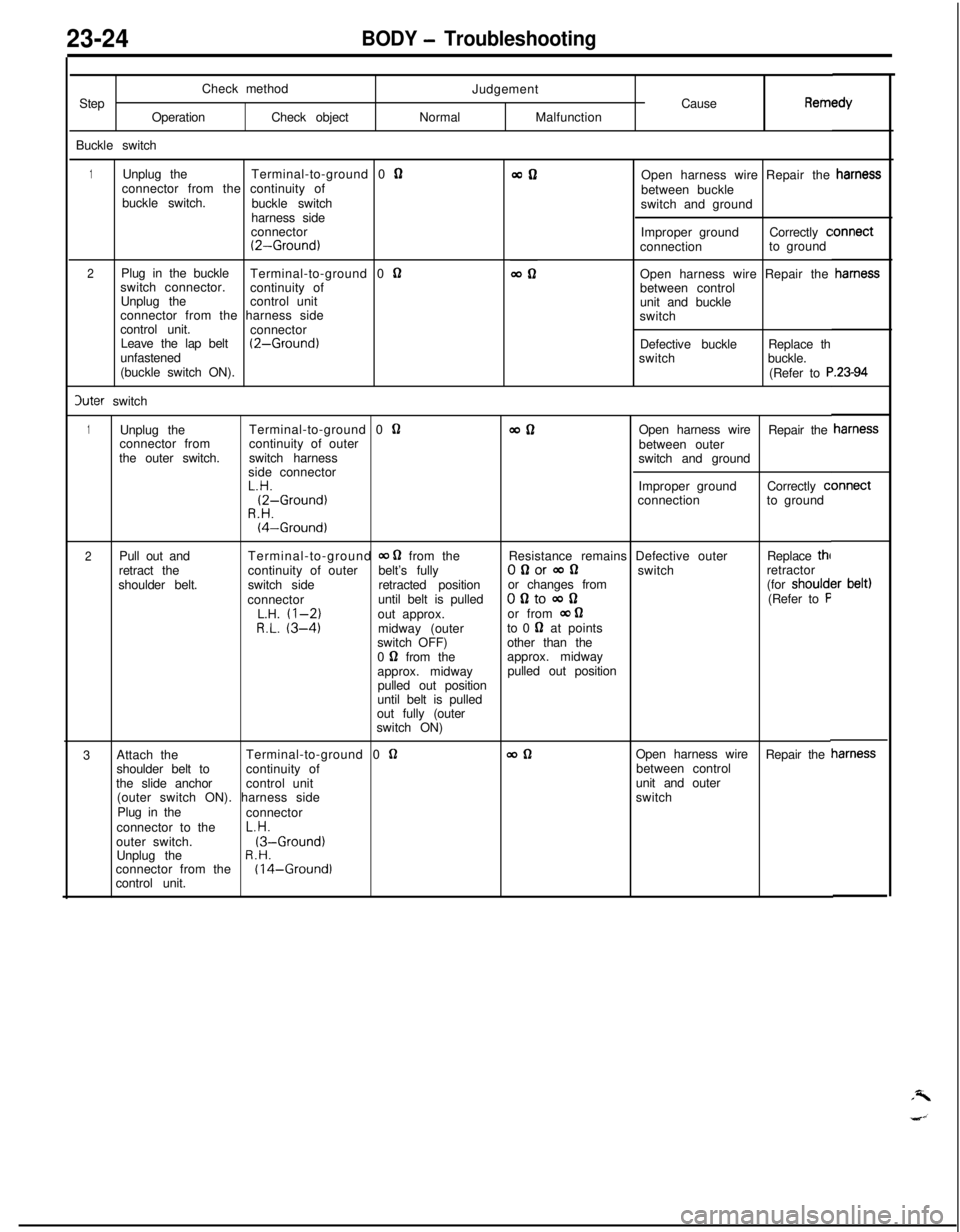
23-24BODY - TroubleshootingCheck method
Step
OperationCheck object
Buckle switchJudgement
Cause
RemINormalMalfunction
1Unplug theTerminal-to-ground 0 Qconnector from the continuity of
buckle switch.
buckle switch
harness side
connector
(2-Ground)
2Plug in the buckle
Terminal-to-ground 0 nswitch connector.
continuity of
Unplug thecontrol unit
connector from the harness side
control unit.
connector
Leave the lap belt
(2-Ground)unfastened
(buckle switch ON).3uter switchOpen harness wire Repair the
between buckle
switch and ground
Improper groundCorrectly
cconnectionto ground
Open harness wire Repair the
between control
unit and buckle
switch
Defective buckleReplace th
switchbuckle.
(Refer to
F
1Unplug theTerminal-to-ground 0 QwflOpen harness wire
Repair the
connector fromcontinuity of outer
between outer
the outer switch.switch harness
switch and ground
side connectorL.H.Improper groundCorrectly
c(2-Ground)connectionto groundR.H.(4-Ground)
2Pull out andTerminal-to-ground 00 0 from theResistance remains Defective outerReplace thl
retract thecontinuity of outerbelt’s fullyOgorconswitchretractor
shoulder belt.switch sideretracted positionor changes from(for should1connectoruntil belt is pulledofltocon(Refer to FL.H. (l-2)out approx.or from 00 62R.L. (3-4)midway (outerto 0 62 at points
switch OFF)other than the
0
0 from theapprox. midway
approx. midwaypulled out position
pulled out position
until belt is pulled
out fully (outer
switch ON)
3Attach theTerminal-to-ground 0
62wdlOpen harness wire
Repair the
shoulder belt tocontinuity ofbetween control
the slide anchorcontrol unitunit and outer
(outer switch ON). harness sideswitch
Plug in the
connector
connector to theL.H.
outer switch.
(3-Ground)Unplug theR.H.connector from the(I 4-Ground)control unit.
Page 1069 of 1216
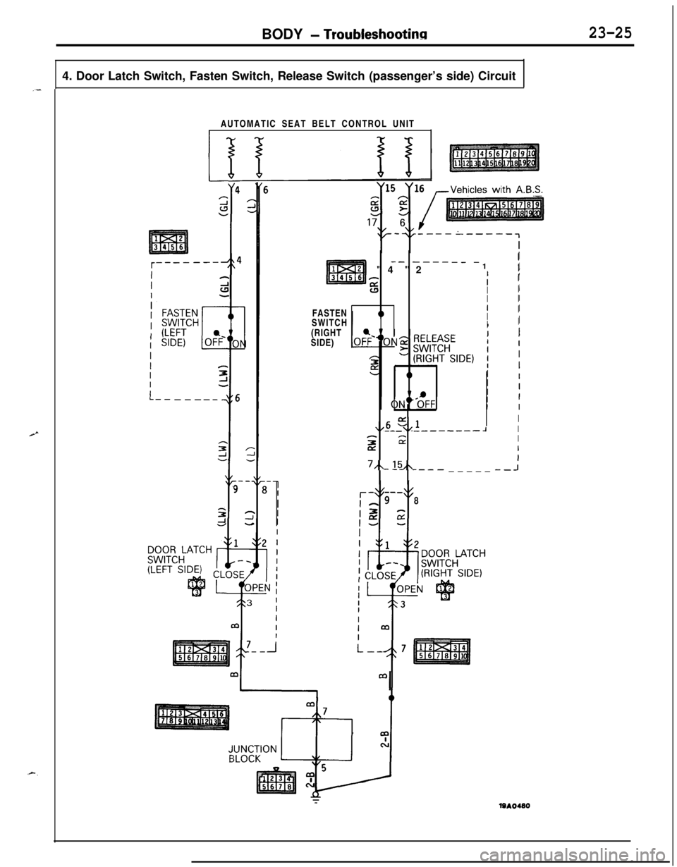
BODY - Troubleshootinn23-254. Door Latch Switch, Fasten Switch, Release Switch (passenger’s side) Circuit
_-AUTOMATIC SEAT BELT CONTROL UNIT
I,
-- -----_ -"4 "21I
ifsII
II
IIFASTEN
I
ISWITCHI
II(RIGHT
SIDE)
,,6 -4,lI--_ _--_----JI
5 2sI
I7,~-15,L--- _____ --J
8
m
I
Page 1072 of 1216
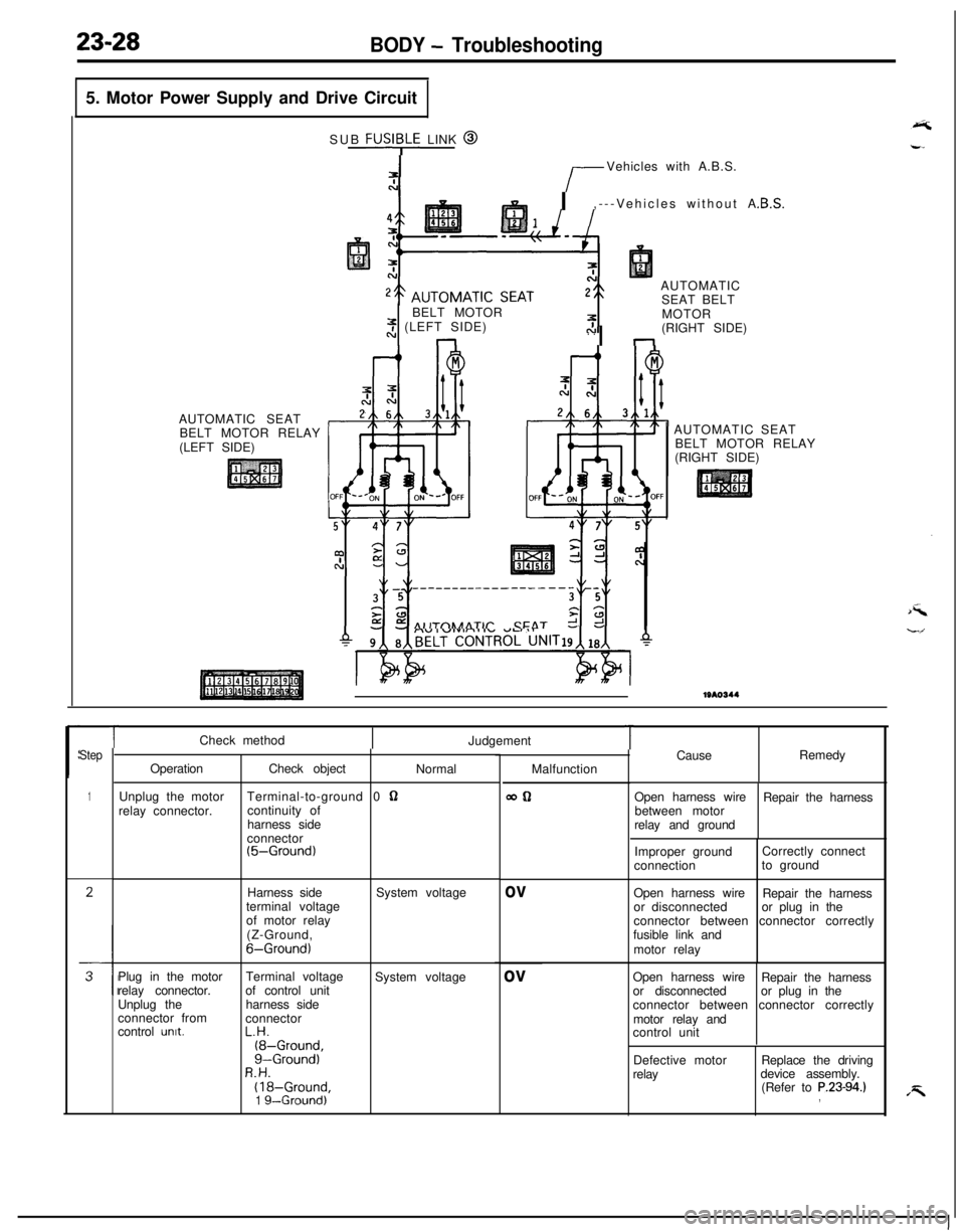
23-28BODY - Troubleshooting5. Motor Power Supply and Drive Circuit
AUTOMATIC SEAT
BELT MOTOR RELAY
(LEFT SIDE)SUB
FUSI;LE LINK @
r-Vehicles with A.B.S.
I,---Vehicles without A
AUTOMATIC
SEAT BELT
BELT MOTOR
2 (LEFT SIDE). .nI nMOTOR
(RIGHT SIDE)
AIITnhAATlr CFAT r!AUTOMATIC SEAT
BELT MOTOR RELAY
(RIGHT SIDE)1310344
Step
1
TCheck method
Judgement
OperationCheck object
Normal
Unplug the motorTerminal-to-ground 0
62relay connector.continuity of
harness side
connector
(5-Ground)Harness side
terminal voltage
of motor relay
(Z-Ground,
6-Ground)System voltage
Plug in the motorTerminal voltage
System voltage
relay connector.of control unit
Unplug theharness side
connector from
connector
control
unit.L.H.(8-Ground,g-Ground)R.H.(18-Ground,1 g--Ground)Malfunction
WQ
ov
ov
TCauseRemedy
Open harness wire
Repair the harness
between motor
relay and ground
Improper groundCorrectly connect
connectionto ground
Open harness wire
Repair the harness
or disconnectedor plug in the
connector between connector correctly
fusible link and
motor relay
Open harness wire
Repair the harness
or disconnectedor plug in the
connector between connector correctly
motor relay and
control unit
Defective motor
relayReplace the driving
device assembly.
(Refer to
P.23-94.),
Page 1073 of 1216
.-
BODY - Troubleshooting
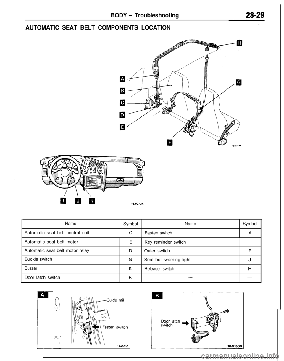
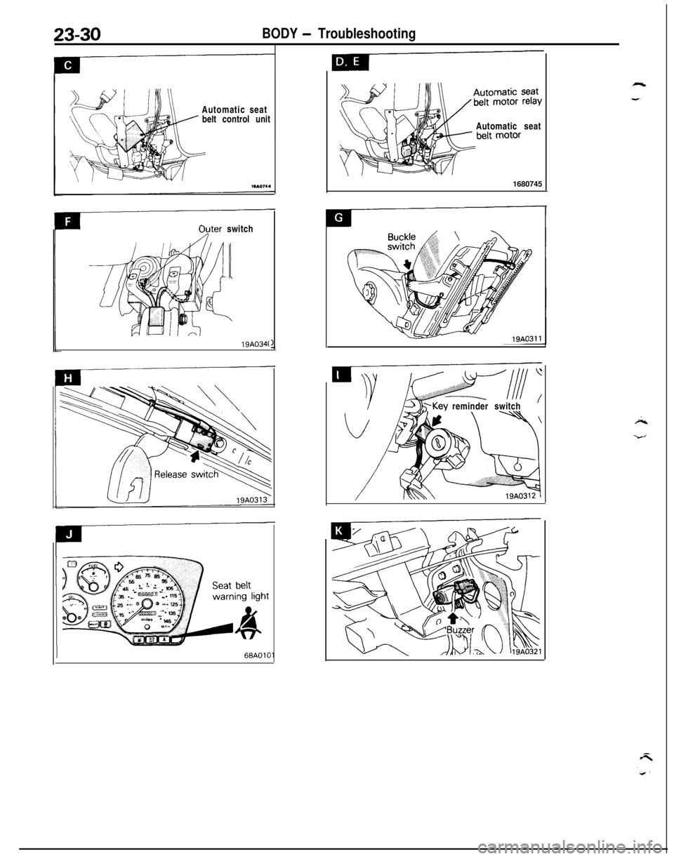
AUTOMATIC SEAT BELT COMPONENTS LOCATION
WA0734
NameSymbolNameSymbolAutomatic seat belt control unit
CFasten switchAAutomatic seat belt motor
Automatic seat belt motor relay
Buckle switch
BuzzerDoor latch switch
EKey reminder switchI
DOuter switchF
GSeat belt warning lightJ
KRelease switchH
B--
A
P
(:0
Page 1074 of 1216
23-30BODY - TroubleshootingAutomatic seat
belt control unit
Ovter switch
19A034(
IAutomatic seat
1680745
reminder switch
Page 1110 of 1216
23-66BODY - Door Trim and Waterproof Film/Door Glass and Regulator
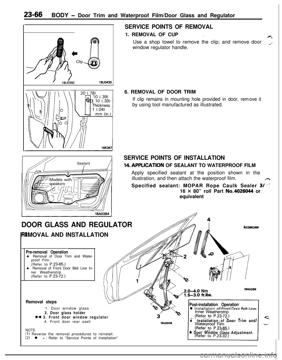
SERVICE POINTS OF REMOVAL1. REMOVAL OF CUP
‘.+iUse a shop towel to remove the clip; and remove door
_Awindow regulator handle.
IbY ISealant!I6. REMOVAL OF DOOR TRIM
If clip remains in mounting hole provided in door, remby using tool manufactured as illustrated.ove it
SERVICE POINTS OF INSTALLATION14,APPLlCATlON OF SEALANT TO WATERPROOF FILM
Apply specified sealant at the position shown in the
illustration, and then attach the waterproof film.
/rSpecified sealant: MOPAR Rope Caulk Sealer
3/ --‘I16
X 80” roll Part No.4026044 or
equivalent
DOOR GLASS AND REGULATORIMOVAL AND INSTALLATION
Pre-removal Operationl Removal of Door Trim and Water-
proof Film
(Refer to P.23-65.)
l Removal of Front Door Belt Line In-
ner Weatherstrip
(Refer to P.23-72.)
N23MCAW2.0-4-O
Nm1.5-3.0 ft.lbs.
Removal steps1. Door window glass
2. Door glass holder
*4 3. Front door window regulator
4. Front door rear sash
NOTEII ) Reverse the removal procedures to reinstall.12) l + : Refer to “Service Points of Installation”
Post-installation Operation0 Installation nf Frnnt lhnr Rnlt I inn
l Installation of Door Trim and
0 Door Window Glass Adjustment
Page 1116 of 1216
23-72BODY -Door Moulding and Drip Line Weatherstrip/Door Mirror
DOOR MOULDING AND DRIP LINE WEATHERSTRIPNZBMFAK
IEMOVAL AND INSTALLATION
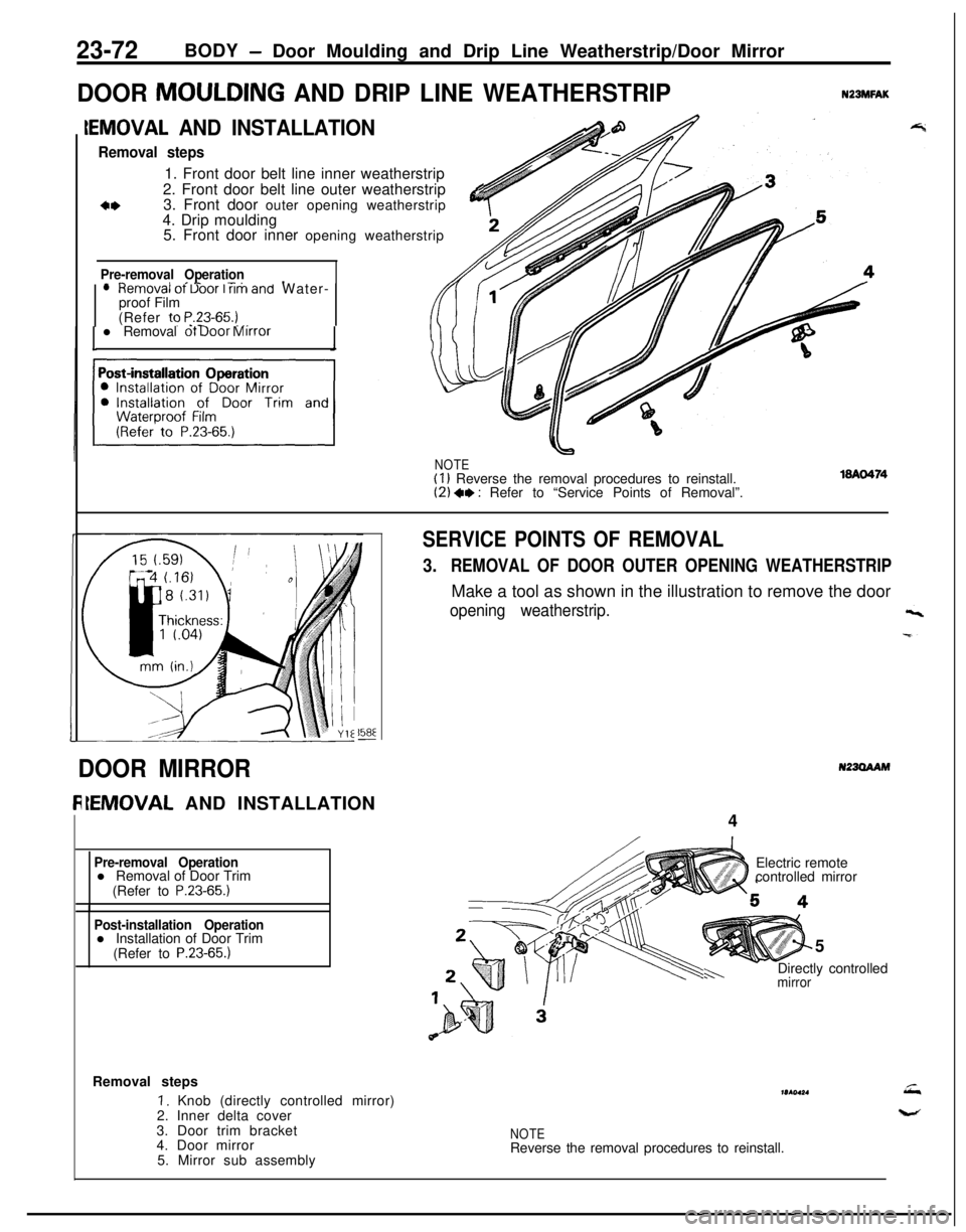
Removal steps1. Front door belt line inner weatherstrip
2. Front door belt line outer weatherstrip
3. Front door outer opening weatherstrip
&4. Drip moulding
5. Front door inner opening weatherstrip
Pre-removal Operation- ^II_ -..lHemOVal ot Uoor I rim and Water-
proof Film
(Refer to
P.23-65.) _,. -l Removal ot Door Mirror
NOTE(I 1 Reverse the removal procedures to reinstall.(2) +, : Refer to “Service Points of Removal”.
158E-
SERVICE POINTS OF REMOVAL
3.REMOVAL OF DOOR OUTER OPENING WEATHERSTRIPMake a tool as shown in the illustration to remove the door
opening weatherstrip.
N23OAAMDOOR MIRROR
IEMOVAL AND INSTALLATION
4
Pre-removal Operationl Removal of Door Trim
(Refer to
P.23-65.)
Post-installation Operationl Installation of Door Trim
(Refer to
P.23-65.)5
mirrorh-.Directly controlled Electric remote
controlled mirror
Removal steps
I. Knob (directly controlled mirror)
2. Inner delta cover
3. Door trim bracket
4. Door mirror
5. Mirror sub assemblymr(ol*.
NOTEReverse the removal procedures to reinstall.
Page 1128 of 1216
23-84BODY - Floor Console
FLOOR CONSOLEN23lJBAP
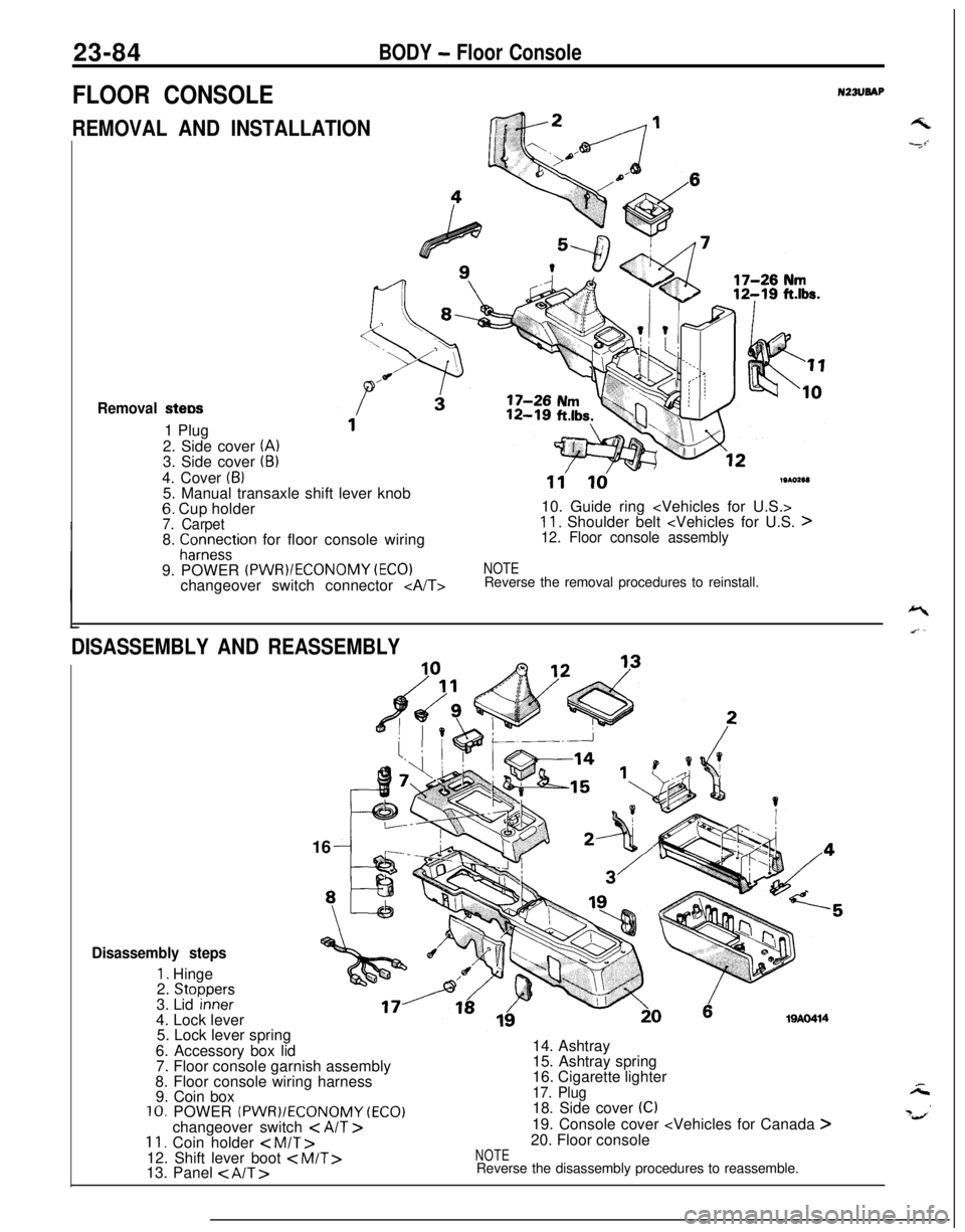
REMOVAL AND INSTALLATIONGk2 /---I
Removal stew1 Plug
2. Side cover
(A)3. Side cover (B)4. Cover
(6)5. Manual transaxle shift lever knob
6. Cup holder7. Carpet8. fCor;e~tion for floor console wiring
9. POWER
(PWR)/ECONOMY (EC01changeover switch connector
11'ld19102e1)10. Guide ring
11. Shoulder belt
NOTEReverse the removal procedures to reinstall.
DISASSEMBLY AND REASSEMBLY16
19AO414
Disassembly steps
1. Hinge
2. Stoooers3. Lid ‘inneF4. Lock lever
5. Lock lever spring
6. Accessory box lid
7. Floor console garnish assembly
8. Floor console wiring harness
9. Coin box
10. POWER (PWR)/ECONOMY (ECO)changeover switch < AIT >11. Coin holder < M/T>12. Shift lever boot
15. Ashtray spring
16. Cigarette lighter
17. Plug18. Side cover (C)19. Console cover
NOTEReverse the disassembly procedures to reassemble.
Page 1129 of 1216
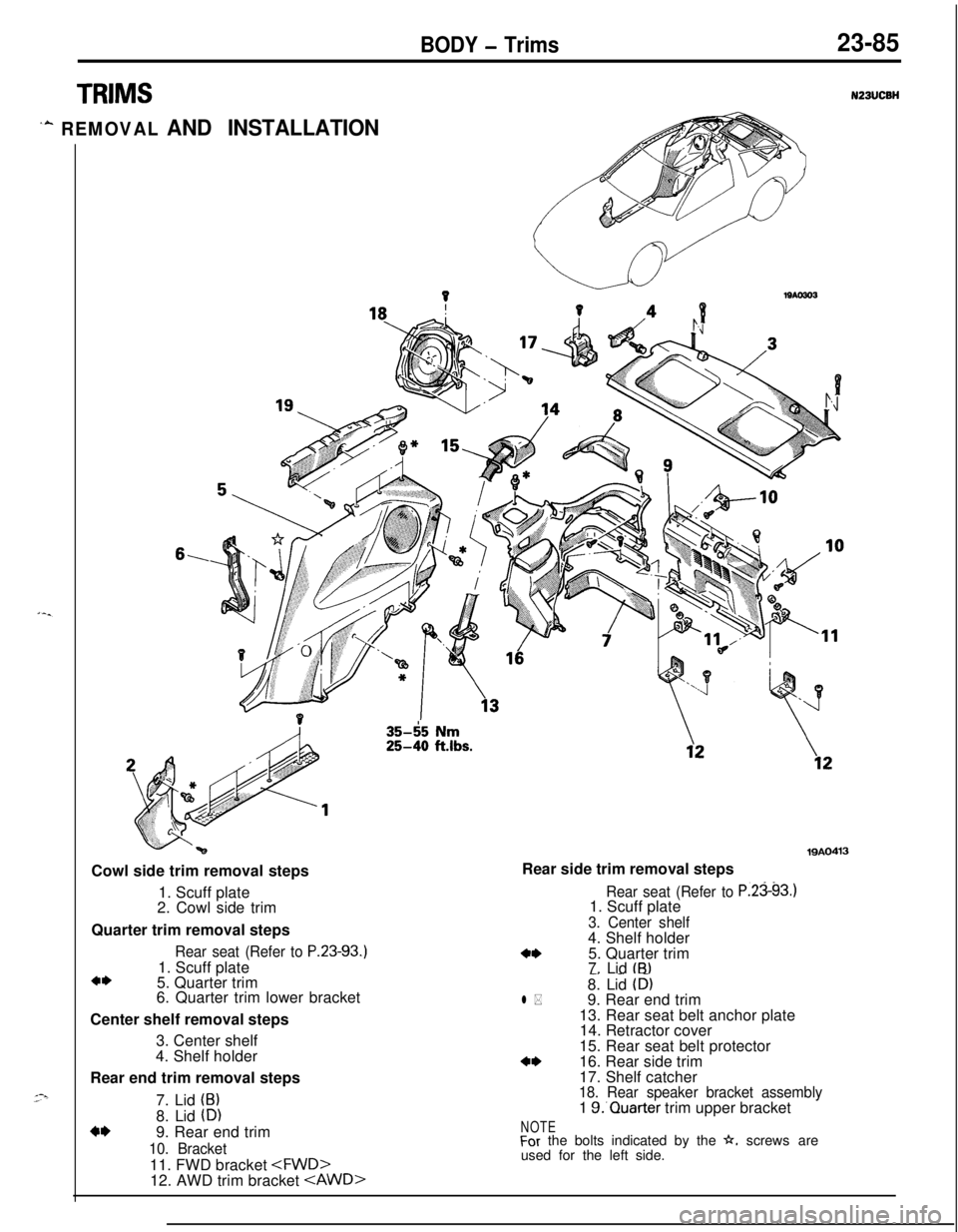
BODY - Trims23-85
TRIMS
‘A REMOVAL AND INSTALLATION
6,Cowl side trim removal steps
1. Scuff plate
2. Cowl side trim
Quarter trim removal steps
Rear seat (Refer to P.23-93.1. Scuff plate
a*5. Quarter trim
6. Quarter trim lower bracket
Center shelf removal steps
3. Center shelf
4. Shelf holder
Rear end trim removal steps
7. Lid
(B)8. Lid
(D)4*9. Rear end trim
10. Bracket11. FWD bracket
35-65 Nm25-40 ftlbs.
19AO413Rear side trim removal steps
Rear seat (Refer to P.2393.11. Scuff plate
3. Center shelf4. Shelf holder
4*5. Quarter trim
7. Lid tB)-. _ -8. Lid (D)l *9. Rear end trim
13. Rear seat belt anchor plate
14. Retractor cover
15. Rear seat belt protector
a*16. Rear side trim
17. Shelf catcher
18. Rear speaker bracket assembly1 S.‘Quarter trim upper bracket
NOTEFor the bolts indicated by the h. screws are
used for the left side.
Page 1130 of 1216
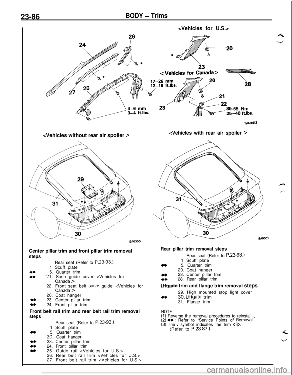
23-86BODY - Trims
-55 Nm
Qi----- %40 ft.lbs.
u.u19AO300
Center pillar trim and front pillar trim removal
steps
404,Rear seat (Refer to P.23-93.)
1 Scuff plate
5. Quarter trim21. Sash guide cover
4,23. Center pillar trimc*24. Front pillar trim
Front belt rail trim and rear belt rail trim removal
steps
4*
4,4*4*Rear seat (Refer to P.23-93.)
1 Scuff plate
5. Quarter trim
20. Coat hanger
23. Center pillar trim
24. Front pillar trim
25. Guide rail
26. Rear belt rail trim
27. Front belt rail trim
19AO412
19AO301
Rear pillar trim removal stepsRear seat (Refer to P.23-93.)
1 Scuff plate
4*5. Quarter trim
20. Coat hanger
4*23. Center pillar trim4*28. Rear pillar trim
Liftgate trim and flange trim removal steps
29. High mounted stop light cover
4*30. Liftgate trim
31. Flange trim
NOTE(1) Reverse the removal procedures to reinstall,.,(2) 4, : Refer to “Service Points of pemoval(3) The l symbol indicates the trim clip.(Refer to P.23-87.)