belt MITSUBISHI ECLIPSE 1991 Manual PDF
[x] Cancel search | Manufacturer: MITSUBISHI, Model Year: 1991, Model line: ECLIPSE, Model: MITSUBISHI ECLIPSE 1991Pages: 1216, PDF Size: 67.42 MB
Page 650 of 1216
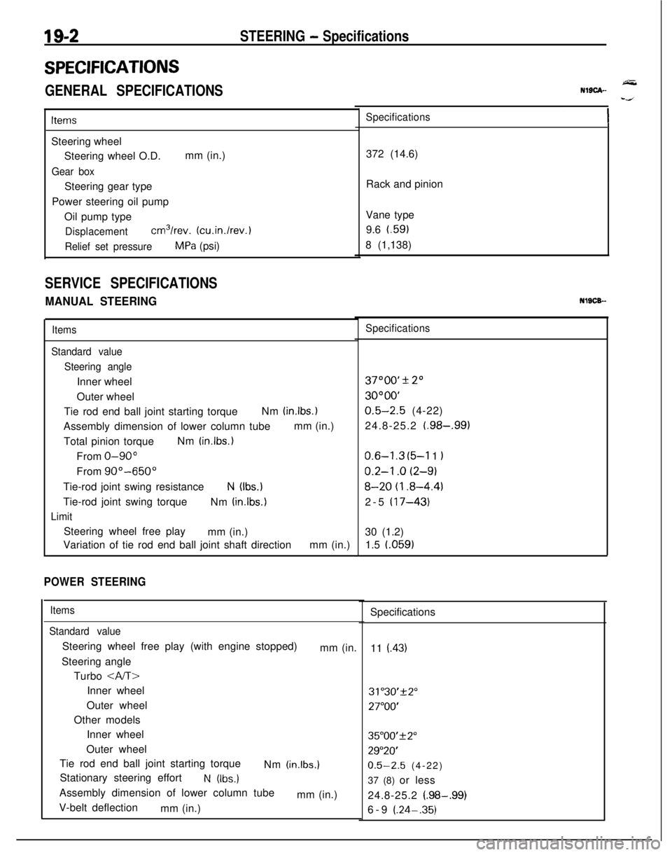
19-2STEERING - Specifications
SPECIFICATIONS
GENERAL SPECIFICATIONS
ItemsSteering wheel
Steering wheel O.D.mm (in.)
Gear boxSteering gear type
Power steering oil pump
Oil pump type
Displacementcm3/rev. (cu.in./rev.)
Relief set pressureMPa (psi)
SERVICE SPECIFICATIONS
MANUAL STEERING
Items
Standard value
Steering angleInner wheel
Outer wheel
Tie rod end ball joint starting torqueNm
(in.lbs.)Assembly dimension of lower column tubemm (in.)
Total pinion torqueNm
(in.lbs.)From
O-90”From
90”-650”Tie-rod joint swing resistance
N (Ibs.)Tie-rod joint swing torque
Nm
(in.lbs.)
LimitSteering wheel free play
mm (in.)
Variation of tie rod end ball joint shaft directionmm (in.)
POWER STEERING
Items
Standard valueSteering wheel free play (with engine stopped)
mm (in.
Steering angle
Turbo
Inner wheel
Outer wheel
Other models
Inner wheel
Outer wheel
Tie rod end ball joint starting torque
Nm
(in.lbs.)Stationary steering effort
N (Ibs.)Assembly dimension of lower column tube
mm (in.)
V-belt deflection
mm (in.)
NlSCA--
Specifications372 (14.6)
Rack and pinion
Vane type
9.6 t.59)
8 (1,138)NlSCB-
Specifications37000’
* 20
3OOOO’
0.5-2.5 (4-22)
24.8-25.2
(.98-,991
0.6-l .3 (5-l 1 I
0.2-l .o (2-9)
8-20 (I .8-4.4)2-5
(17-43)30 (1.2)
1.5 l.059)
Specifications
11
(.43)
31"30'+2"
27"OO'
35"00'f2"
29"20'
0.5-2.5 (4-22)
37 (8) or less
24.8-25.2
(.98-.99)6-9 (.24-.35)
Page 660 of 1216
19-12STEERING - Service Adjustment Procedures
Pressure ofWater pump
pulleyOlA0059Fluid fluctuation
While engine
runningWhile enginestopped13uo139
Return hoseVinyl hose
x ,3Ao,42-
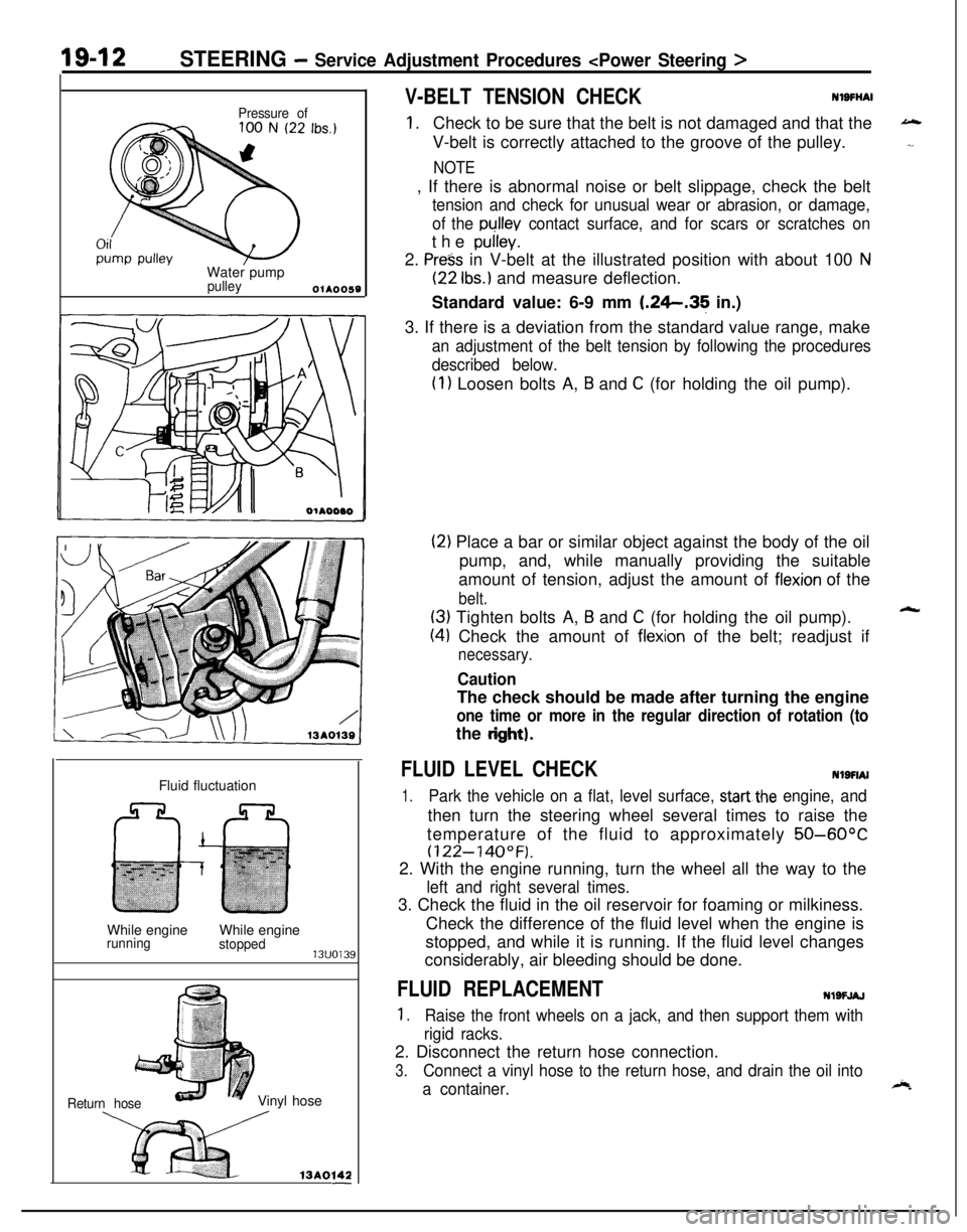
V-BELT TENSION CHECKNlSFliAl
1.Check to be sure that the belt is not damaged and that the
V-belt is correctly attached to the groove of the pulley.
NOTE, If there is abnormal noise or belt slippage, check the belt
tension and check for unusual wear or abrasion, or damage,
of the
pullev contact surface, and for scars or scratches onthe
pulley.2.
Press in V-belt at the illustrated position with about 100 N
(22 Ibs.) and measure deflection.
Standard value: 6-9 mm
1.26.35 in.)
3. If there is a deviation from the standard value range, make
an adjustment of the belt tension by following the procedures
described below.
(1) Loosen bolts A, B and C (for holding the oil pump).
(2) Place a bar or similar object against the body of the oil
pump, and, while manually providing the suitable
amount of tension, adjust the amount of
flexion of the
belt.
(3) Tighten bolts A, B and C (for holding the oil pump).
(4) Check the amount of flexion of the belt; readjust if
necessary.
CautionThe check should be made after turning the engine
one time or more in the regular direction of rotation (tothe
dght).
FLUID LEVEL CHECKNlSFIAI
1.Park the vehicle on a flat, level surface, startthe engine, andthen turn the steering wheel several times to raise the
temperature of the fluid to approximately
50-60°C
(122-140°F).2. With the engine running, turn the wheel all the way to the
left and right several times.3. Check the fluid in the oil reservoir for foaming or milkiness.
Check the difference of the fluid level when the engine is
stopped, and while it is running. If the fluid level changes
considerably, air bleeding should be done.
FLUID REPLACEMENTNlSFJAJ
1.Raise the front wheels on a jack, and then support them with
rigid racks.2. Disconnect the return hose connection.
3.Connect a vinyl hose to the return hose, and drain the oil into
a container.
Page 687 of 1216
STEERING - Power Steering Oil Pump1849
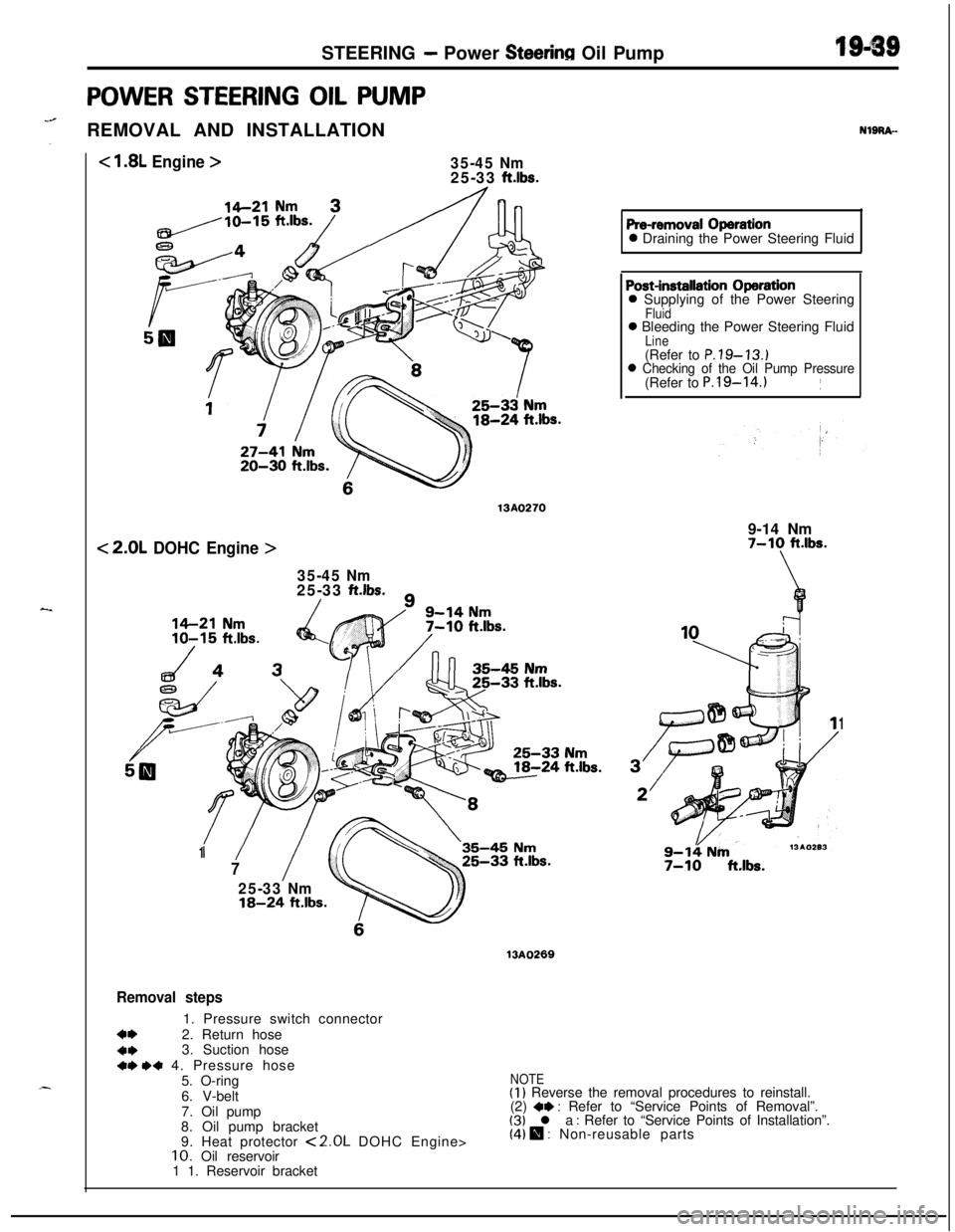
POWER STEERING OIL PUMP
“@REMOVAL AND INSTALLATION
< 1.8L Engine >35-45 Nm25-33 ft.lbs.
20-30 ft.lbs.
13A0270
< 2.0L DOHC Engine >
35-45 Nm25-33 ft.lbs./
NlgRA-
Pre-removal Operation0 Draining the Power Steering Fluid
‘/1
7
25-33 Nm18-24 ft.lbs.
35-45 Nm
Post-installation Operation0 Supplying of the Power Steering
Fluid0 Bleeding the Power Steering Fluid
Line(Refer to P.79-13.)0 Checking of the Oil Pump Pressure(Refer to P.l9-14.)~
9-14 Nm
7-10 ft.lbs.
\
1
9-14 Nm7-10 ft.lbs.
13AO269
Removal steps1. Pressure switch connector
a*2. Return hose
4*3. Suction hose+r) .+ 4. Pressure hose
5. O-ring
6. V-belt
7. Oil pump
8. Oil pump bracket
9. Heat protector
<2.0L DOHC Engine>10. Oil reservoir
1 1. Reservoir bracket
NOTE(I) Reverse the removal procedures to reinstall.
(2) *I) : Refer to “Service Points of Removal”.(3) l a : Refer to “Service Points of Installation”.(4) 0 : Non-reusable parts
Page 688 of 1216
1 S-40STEERING - Power Steering Oil Pump
SERVICE POINTS OF REMOVAL
Nl8RW2. DISCONNECTION OF RETURN HOSE
(1) Removal the reservoir cap and disconnect the return
hose from the reservoir to drain the fluid.
(2) Jack up the front wheels.
(3) Disconnect the high tension cable and turn the engine
over several times to drain the fluid from the gear box.
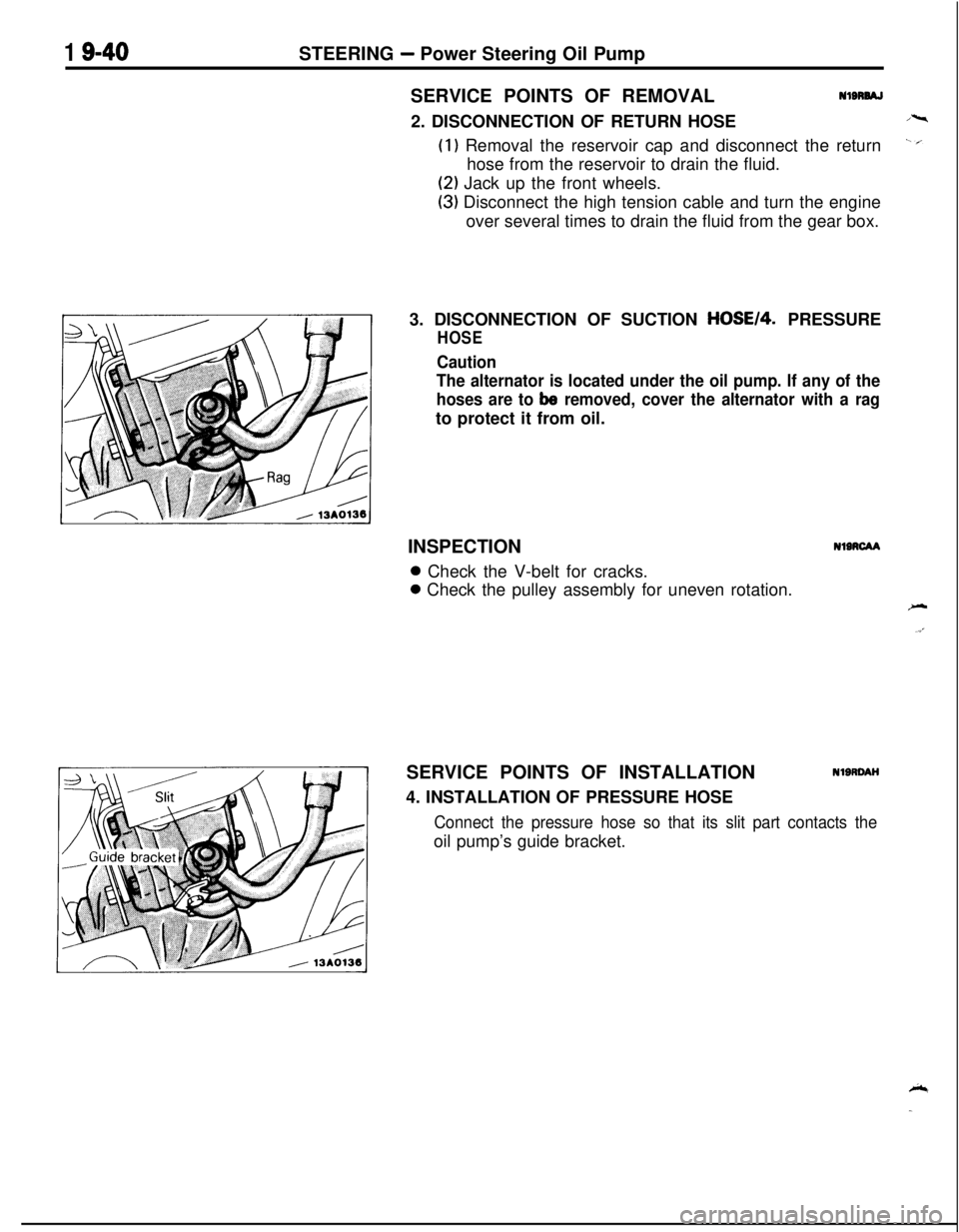
3. DISCONNECTION OF SUCTION
HOSE14. PRESSURE
HOSE
Caution
The alternator is located under the oil pump. If any of the
hoses are to
be removed, cover the alternator with a ragto protect it from oil.
INSPECTION
NIRCAA0 Check the V-belt for cracks.0 Check the pulley assembly for uneven rotation.
SERVICE POINTS OF INSTALLATION
4. INSTALLATION OF PRESSURE HOSE
NlSRDAH
Connect the pressure hose so that its slit part contacts theoil pump’s guide bracket.
Page 703 of 1216
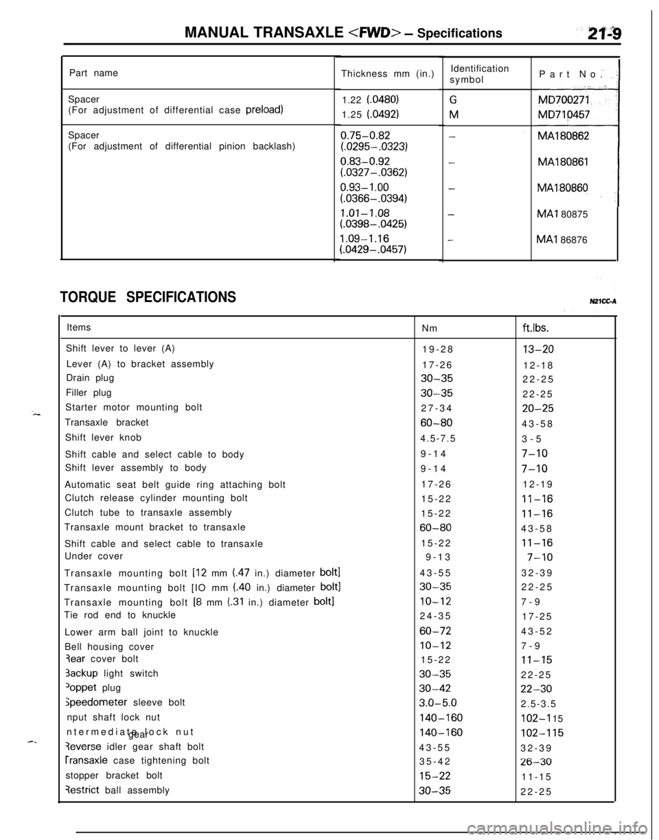
MANUAL TRANSAXLE
Part name
Spacer
(For adjustment of differential case preload)
Spacer
(For adjustment of differential pinion backlash)
TORQUE SPECIFICATIONSThickness mm (in.)
1.22 f.0480)
1.25 (.0492)
0.75-0.82
(.0295-.0323)
0.83-0.92
(.0327-.0362)
0.93- 1 .oo
(.0366-.0394)
1.01-1.08
(.0398-.0425)
1.09-1.16
(.0429-.0457)Identification
symbol
GM
-
-
-
-Part No.
MA180862MA1
80866MA1 80875MA1 86876
Items
Nm
Shift lever to lever (A)
19-28
Lever (A) to bracket assembly
17-26
Drain plug
30-35Filler plug
30-35Starter motor mounting bolt
27-34
Transaxle bracket
60-80Shift lever knob
4.5-7.5
Shift cable and select cable to body9-14
Shift lever assembly to body
9-14
Automatic seat belt guide ring attaching bolt17-26
Clutch release cylinder mounting bolt
15-22
Clutch tube to transaxle assembly
15-22
Transaxle mount bracket to transaxle
60-80Shift cable and select cable to transaxle15-22
Under cover
9-13
Transaxle mounting bolt [12 mm (.47 in.) diameter
bolt143-55
Transaxle mounting bolt [IO mm (.40 in.) diameter
bolt130-35Transaxle mounting bolt
[8 mm (.31 in.) diameter bolt]IO-12Tie rod end to knuckle
24-35
Lower arm ball joint to knuckle
60-72Bell housing cover
IO-123ear cover bolt
15-223ackup light switch
30-35
loppet plug30-42
jpeedometer sleeve bolt3.0-5.0nput shaft lock nut
140-160ntermediate lock nut
gear
140-160
3everse idler gear shaft bolt
43-55
rransaxle case tightening bolt
35-42
stopper bracket bolt
15-22
qestrict ball assembly30-35
ft.lbs.
13-2012-18
22-25
22-25
20-2543-58
3-5
7-10
7-1012-19
11-16
11-1643-58
11-16
7-1032-39
22-25
7-9
17-25
43-52
7-9
11-1522-25
22-302.5-3.5
102-I 15
102-11532-39
26-3011-15
22-25
Page 709 of 1216
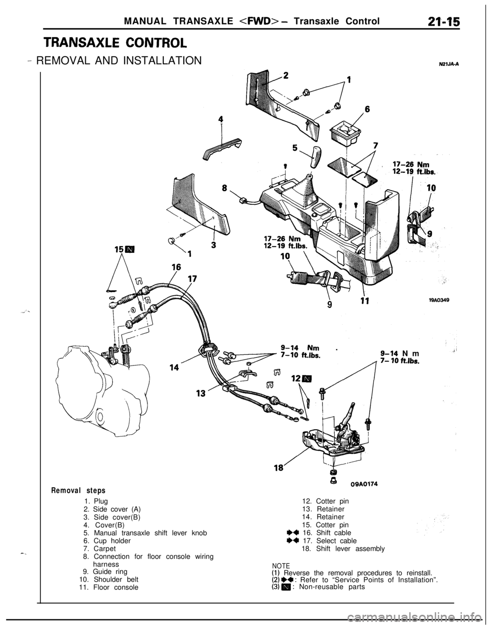
MANUAL TRANSAXLE
TRANSAXLE CONTROL
-^ REMOVAL AND INSTALLATION
Removal steps1. Plug
2. Side cover (A)
3. Side cover(B)
4. Cover(B)
N21JA-A
919AO349
9-14 Nm .
+-
0
0OQA017412. Cotter pin
13. Retainer
14. Retainer
15. Cotter pin
9-14 Nm7- 10 ftlbs.5. Manual transaxle shift lever knob
6. Cup holder
7. Carpet
8. Connection for floor console wiring
I)4 16. Shift cable
I)+ 17. Select cable
18. Shift lever assembly
harness
9. Guide ring
10. Shoulder belt
11. Floor console
NOTE(1) Reverse the removal procedures to reinstall.(2) *a : Refer to “Service Points of Installation”.(3) m : Non-reusable parts
Page 860 of 1216
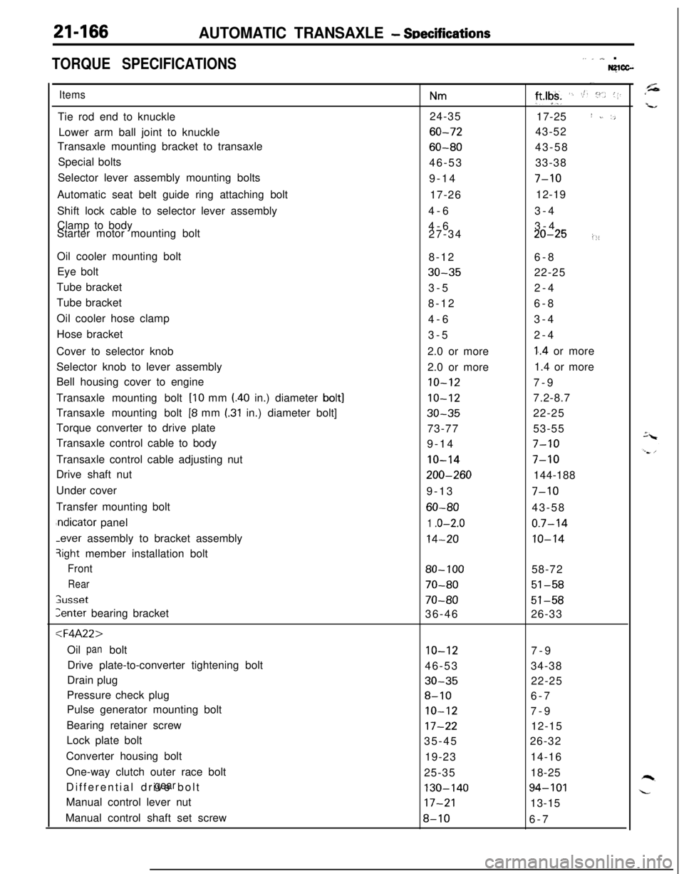
21-166AUTOMATIC TRANSAXLE - SDecifications
TORQUE SPECIFICATIONS,. _ ,,,_ .Nglcc-
ItemsTie rod end to knuckle
Lower arm ball joint to knuckle
Transaxle mounting bracket to transaxle
Special bolts
Selector lever assembly mounting bolts
Automatic seat belt guide ring attaching bolt
Shift lock cable to selector lever assembly
Clamp to body
Starter motor mounting bolt
Oil cooler mounting bolt
Eye bolt
Tube bracket
Tube bracket
Oil cooler hose clamp
Hose bracket
Cover to selector knob
Selector knob to lever assembly
Bell housing cover to engine
Transaxle mounting bolt
[lo mm l.40 in.) diameter bolt]Transaxle mounting bolt
[8 mm I.31 in.) diameter bolt]
Torque converter to drive plate
Transaxle control cable to body
Transaxle control cable adjusting nut
Drive shaft nut
Under cover
Transfer mounting boltndicator panel-ever assembly to bracket assembly
3ight member installation bolt
Front
Rear
;usset
Zenter bearing bracket
:l=4A22>Oil bolt
panDrive plate-to-converter tightening bolt
Drain plug
Pressure check plug
Pulse generator mounting bolt
Bearing retainer screw
Lock plate bolt
Converter housing bolt
One-way clutch outer race bolt
Differential drive bolt
gearManual control lever nut
Manual control shaft set screw
Nm24-35
60-72
60-8046-53
9-14
17-26
4-6
4-6
27-34
8-12
30-353-5
8-12
4-6
3-5
2.0 or more
2.0 or more
10-12
10-12
30-3573-77
9-14
IO-14
200-2609-13
60-80
1 .o-2.0
14-20
80- 100
70-80
70-8036-46
10-1246-53
30-35
8-10
IO-12
17-2235-45
19-23
25-35
130-14017-21
8-10
-.
ft*lgk+ ‘. St. :“.. (1.17-25
I ~. ‘,43-52
43-58
33-38
7-1012-19
3-4
3-4
20-25i::6-8
22-25
2-4
6-8
3-4
2-4
1..4 or more
1.4 or more
7-9
7.2-8.7
22-25
53-55
7-10
7-10144-188
7-1043-58
0.7-14
10-1458-72
51-58
51-5826-33
7-9
34-38
22-25
6-7
7-9
12-15
26-32
14-16
18-25
94-10113-15
6-7
Page 911 of 1216
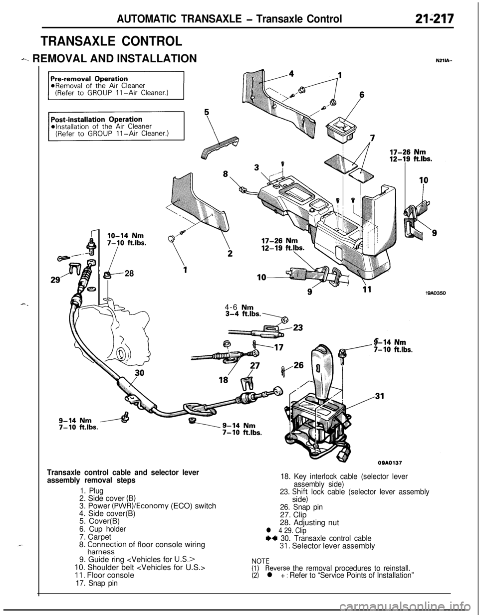
AUTOMATIC TRANSAXLE - Transaxle Control21-217
TRANSAXLE CONTROL
dl_i REMOVAL AND INSTALLATIONNZlub-
-.
lo-14 Nm7-10 ft.lbs.
i284-6
Nm
y-14 Nm7-10 ft.lbs.
Transaxle control cable and selector lever
assembly removal steps
1. Plug2. Side cover (B)3. Power (PWR)/Economy (ECO) switch
4. Side cover(B)
5. Cover(B)
6. Cup holder7. Carpet
8.
EZrreTstion of floor console wiring
9. Guide ring
IO. Shoulder belt
17. Snap pin18. Key interlock cable (selector lever
assembly side)
23.
S$i; lock cable (selector lever assembly
26. Snap pin27. Clip
28. Adjusting nut
l 4 29. Clip++ 30. Transaxle control cable31. Selector lever assembly
zykeverse the removal procedures to reinstall.(2) l + : Refer to “Service Points of Installation”
Page 912 of 1216
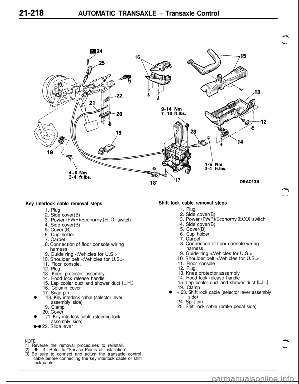
2l-218AUTOMATIC TRANSAXLE - Transaxle Control
724
169-14
Nm7-10 ftlbs.7
\\4-6 Nm3-4 ft.lbs.3-4
ft.lbs.
Key interlock cable removal steps
1. Plug2. Side cover(B)
3. Power
(PWR)/Economy (ECO) switch
4. Side cover(B)
5. Cover
(B)6. Cup holder7. Carpet
8.
;ir;eystion of floor console wiring
9. Guide ring
10. Shoulder belt
12. Plug
13. Knee protector assembly
14. Hood lock release handle
15. Lap cooler duct and shower duct
(L.H.)16. Column cover
17. Snap pin
l + 18. Key interlock cable (selector lever
assembly side)
19. Clamp20. Cover
l + 21, Key interlock cable (steering lock
assembly side)
e+ 22. Slide lever
NOTE(I) Reverse the removal procedures to reinstall.(2) l 4 : Refer to “Service Points of Installation”.(3) Be sure to connect and adjust the transaxle control
cable before connecting the key interlock cable or shift
lock cable18'
‘1709A0138
Shift lock cable removal steps
1. Plug2. Side cover(B)
3. Power
(PWR)/Economv (EC01 switch
4. Side cover(B)
’5. Cover(B)
6. Cup holder7. Carpet
8. Connection of floor console wiring
harness9. Guide ring
10. Shoulder belt
11. Floor console
12. Plug13. Knee protector assembly
14. Hood lock release handle
15. Lap cooler duct and shower duct (L.H.)19. Clamp
l + 23. :izs lock cable (selector lever assembly24. Split pin
25. Shift lock cable (brake pedal side)
Page 1045 of 1216
23-lBODY
CONTENTSN23Ak-
AERO PARTS..........................................74
CENTRAL DOOR LOCKING SYSTEM...........70
DOOR ASSEMBLY....................................63
DOOR GLASS AND REGULATOR................66
DOORHANDLEANDLATCH.....................69
DOOR MIRROR........................................72
DOOR MOULDING AND
DRIP LINE WEATHERSTRIP........................72
....DOOR RUNCHANNEL...............................71
DOOR TRIM AND WATERPROOF FILM........65
ELECTRIC REMOTE CONTROLLED
MIRROR SWITCH.....................................73
FENDER..................................................51
FLOOR CONSOLE....................................84
FRONT BUMPER......................................39
FRONT SEAT..........................................90
FUEL TANKFILLERDOOR.........................38
GARNISHES............................................47
HEADLINING...........................................89
HOOD....................................................34
INSTRUMENT PANEL................................79
LIFTGATE...............................................36
LIFTGATE WINDOWGLASS......................62
LOOSE PANEL.........................................53
MOULDING.............................................48
POWER WINDOW....................................67
QUARTERWINDOWGLASS......................61
REAR BUMPER........................................43
REAR SEAT............................................93
SEAT BELT.............................................94
SERVICE ADJUSTMENT PROCEDURES........31
Door Adjustment....................................32
Door Glass Adjustment............................32Door Inside Handle Play Check..................
32
Door Outside Handle Play Check................32
Floor PanInspection...............................
33Fuel Filler Door Adjustment.......................
31
Hood Adjustment...................................31
Liftgate Adjustment.................................31
Water Test...........................................33
SPECIAL TOOLS......................................5
SPECIFICATIONS.....................................2
General Specifications..............................
2
Lubricants.............................................5
Sealants and Adhesives...........................5
Service Specifications..............................3
Torque Specifications..............................3
SUNROOF...............................................77TRIMS
....................................................85
TROUBLESHOOTING................................6WINDOW
GLASS.....................................54
WINDSHIELD...........................................58