check oil MITSUBISHI ECLIPSE 1991 Service Manual
[x] Cancel search | Manufacturer: MITSUBISHI, Model Year: 1991, Model line: ECLIPSE, Model: MITSUBISHI ECLIPSE 1991Pages: 1216, PDF Size: 67.42 MB
Page 13 of 1216
INTRODUCTION AND MASTER TROUBLESHOOTING - Precautions befdre Service‘1 S
OOV663OOY192
FOOO 1.
FOOO18
0
OOD511
J7
PRECAUTIONS BEFORE SERVICE wxww
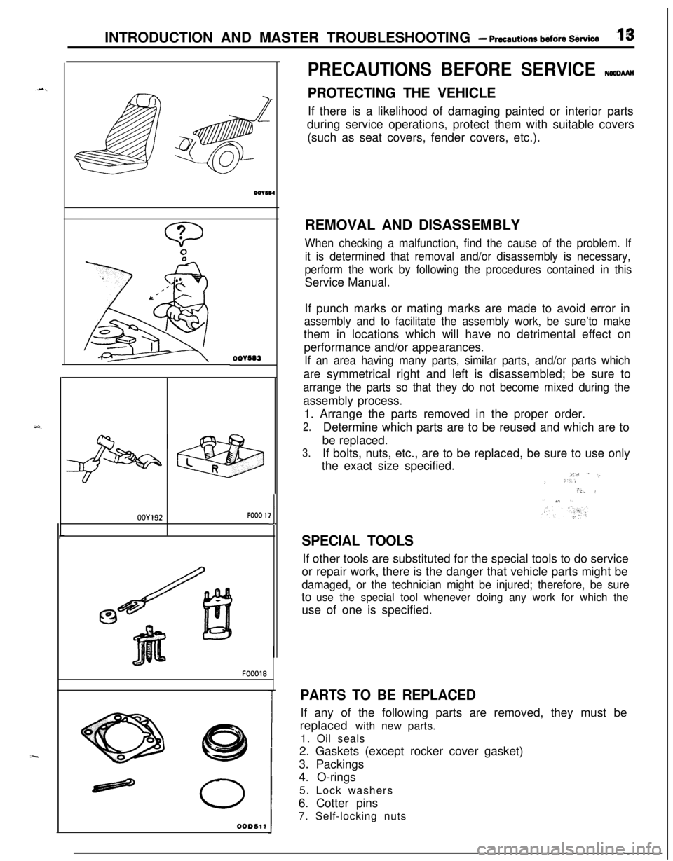
PROTECTING THE VEHICLEIf there is a likelihood of damaging painted or interior parts
during service operations, protect them with suitable covers
(such as seat covers, fender covers, etc.).
REMOVAL AND DISASSEMBLY
When checking a malfunction, find the cause of the problem. If
it is determined that removal and/or disassembly is necessary,
perform the work by following the procedures contained in thisService Manual.
If punch marks or mating marks are made to avoid error in
assembly and to facilitate the assembly work, be sure’to makethem in locations which will have no detrimental effect on
performance and/or appearances.
If an area having many parts, similar parts, and/or parts whichare symmetrical right and left is disassembled; be sure to
arrange the parts so that they do not become mixed during theassembly process.
1. Arrange the parts removed in the proper order.
2.Determine which parts are to be reused and which are to
be replaced.
3.If bolts, nuts, etc., are to be replaced, be sure to use only
the exact size specified.
i:c ” -,.> ‘..“i,. i” ,,‘. 5,
SPECIAL TOOLSIf other tools are substituted for the special tools to do service
or repair work, there is the danger that vehicle parts might be
damaged, or the technician might be injured; therefore, be sureto use the special tool whenever doing any work for which the
use of one is specified.
PARTS TO BE REPLACEDIf any of the following parts are removed, they must be
replaced with new parts.
1. Oil seals
2. Gaskets (except rocker cover gasket)
3. Packings
4. O-rings
5. Lock washers
6. Cotter pins
7. Self-locking nuts
Page 37 of 1216
LUBRICATION AND MAINTENANCE - Scheduled MaintenanCe Table. &3
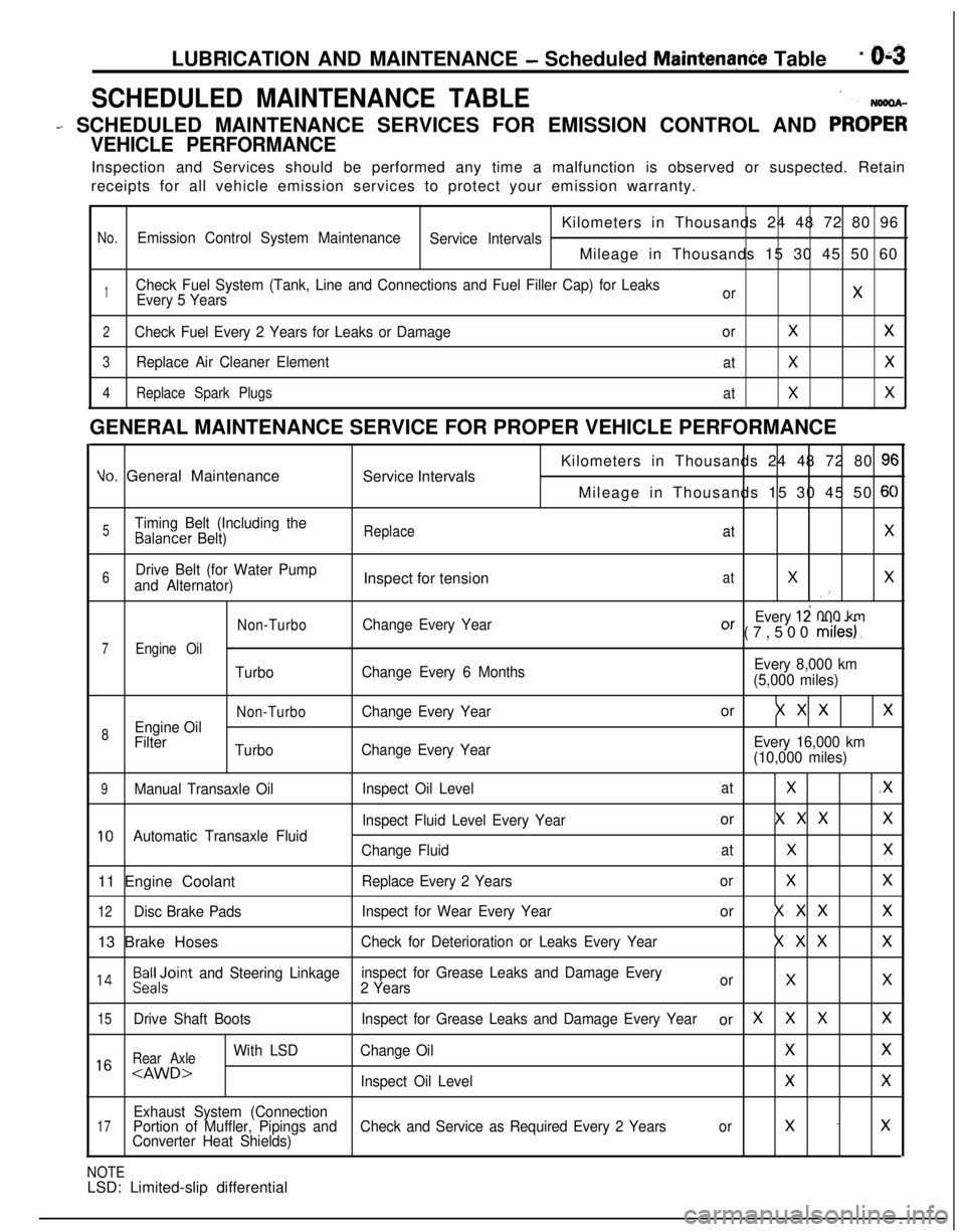
SCHEDULED MAINTENANCE TABLE1
- SCHEDULED MAINTENANCE SERVICES FOR EMISSION CONTROL AND PRO;;
VEHICLE PERFORMANCEInspection and Services should be performed any time a malfunction is observed or suspected. Retain
receipts for all vehicle emission services to protect your emission warranty.
Kilometers in Thousands 24 48 72 80 96
No.Emission Control System Maintenance
Service IntervalsMileage in Thousands 15 30 45 50 60
1Check Fuel System (Tank, Line and Connections and Fuel Filler Cap) for Leaks
Every 5 YearsorX
2Check Fuel Every 2 Years for Leaks or DamageorXX
3Replace Air Cleaner Element
atXX
4Replace Spark Plugs
atXXGENERAL MAINTENANCE SERVICE FOR PROPER VEHICLE PERFORMANCE
Yo. General Maintenance
Service IntervalsKilometers in Thousands 24 48 72 80 9cMileage in Thousands 15 30 45 50
6C
5Timing Belt (Including theBalancer Belt)ReplaceatX
6Drive Belt (for Water Pump
and Alternator)Inspect for tensionatXX.’
Non-TurboChange Every YearEvery 12 000 kmOr (7,500 miles).
7Engine Oil
TurboChange Every 6 MonthsEvery 8,000 km
(5,000 miles)
Non-TurboChange Every Yearor X X XX
8Engine Oil
Filter
TurboChange Every YearEvery 16,000 km
(10,000 miles)
9Manual Transaxle OilInspect Oil LevelatX.X
Inspect Fluid Level Every Yearor X X XX
10Automatic Transaxle Fluid
Change FluidatXX11 Engine Coolant
Replace Every 2 YearsorXX
12Disc Brake PadsInspect for Wear Every Yearor X X XX13 Brake Hoses
Check for Deterioration or Leaks Every YearX X XX
l 4Beiloint and Steering Linkageinspect for Grease Leaks and Damage Every
2 YearsorXX
15Drive Shaft BootsInspect for Grease Leaks and Damage Every Yearor XXXX
Rear Axle
With LSDChange OilXX1 6
Exhaust System (Connection17Portion of Muffler, Pipings andCheck and Service as Required Every 2 Yearsorx -xConverter Heat Shields)
NOTELSD: Limited-slip differential
Page 43 of 1216
LUBRICATION AND MAINTENANCE - Maintenance ServiceO-9
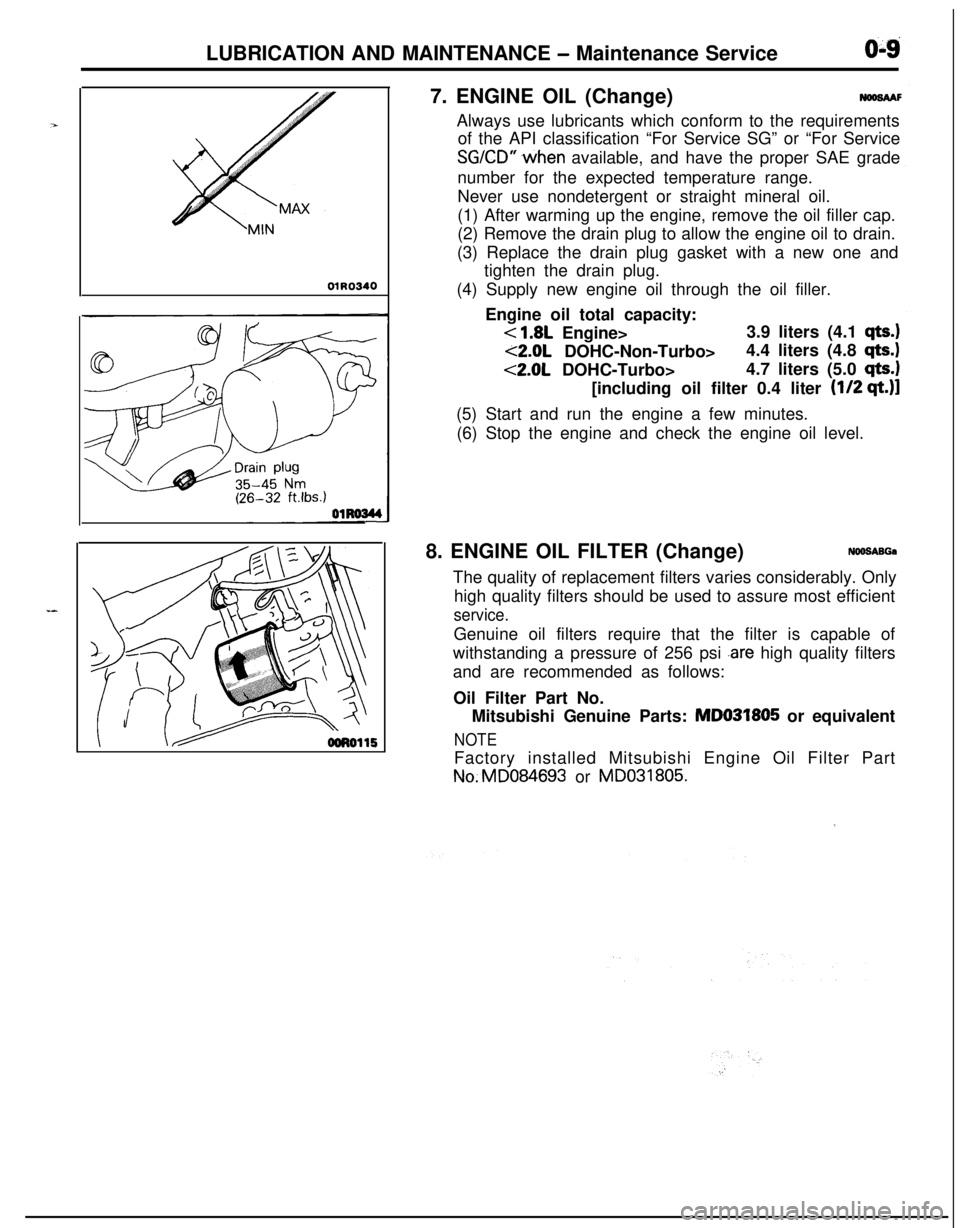
01R03407. ENGINE OIL (Change)
NWSAAFAlways use lubricants which conform to the requirements
of the API classification “For Service SG” or “For Service
SGKD” .when available, and have the proper SAE grade
number for the expected temperature range.
Never use nondetergent or straight mineral oil.
(1) After warming up the engine, remove the oil filler cap.
(2) Remove the drain plug to allow the engine oil to drain.
(3) Replace the drain plug gasket with a new one and
tighten the drain plug.
(4) Supply new engine oil through the oil filler.
Engine oil total capacity:
< 1.8L Engine>3.9 liters (4.1 qts.)
<2.0L DOHC-Non-Turbo>4.4 liters (4.8 qts.)
<2.0L DOHC-Turbo>4.7 liters (5.0 qts.1[including oil filter 0.4 liter
(l/2 qt.)]
(5) Start and run the engine a few minutes.
(6) Stop the engine and check the engine oil level.
8. ENGINE OIL FILTER (Change)
NOO!SABGaThe quality of replacement filters varies considerably. Only
high quality filters should be used to assure most efficient
service.Genuine oil filters require that the filter is capable of
withstanding a pressure of 256 psi
.are high quality filters
and are recommended as follows:
Oil Filter Part No.
Mitsubishi Genuine Parts: MD031805 or equivalent
NOTEFactory installed Mitsubishi Engine Oil Filter PartNo.MD084693 or MD031805.
’
Page 44 of 1216
LUBRICATION AND MAINTENANCE - Maintenance Service
osFol2ENGINE
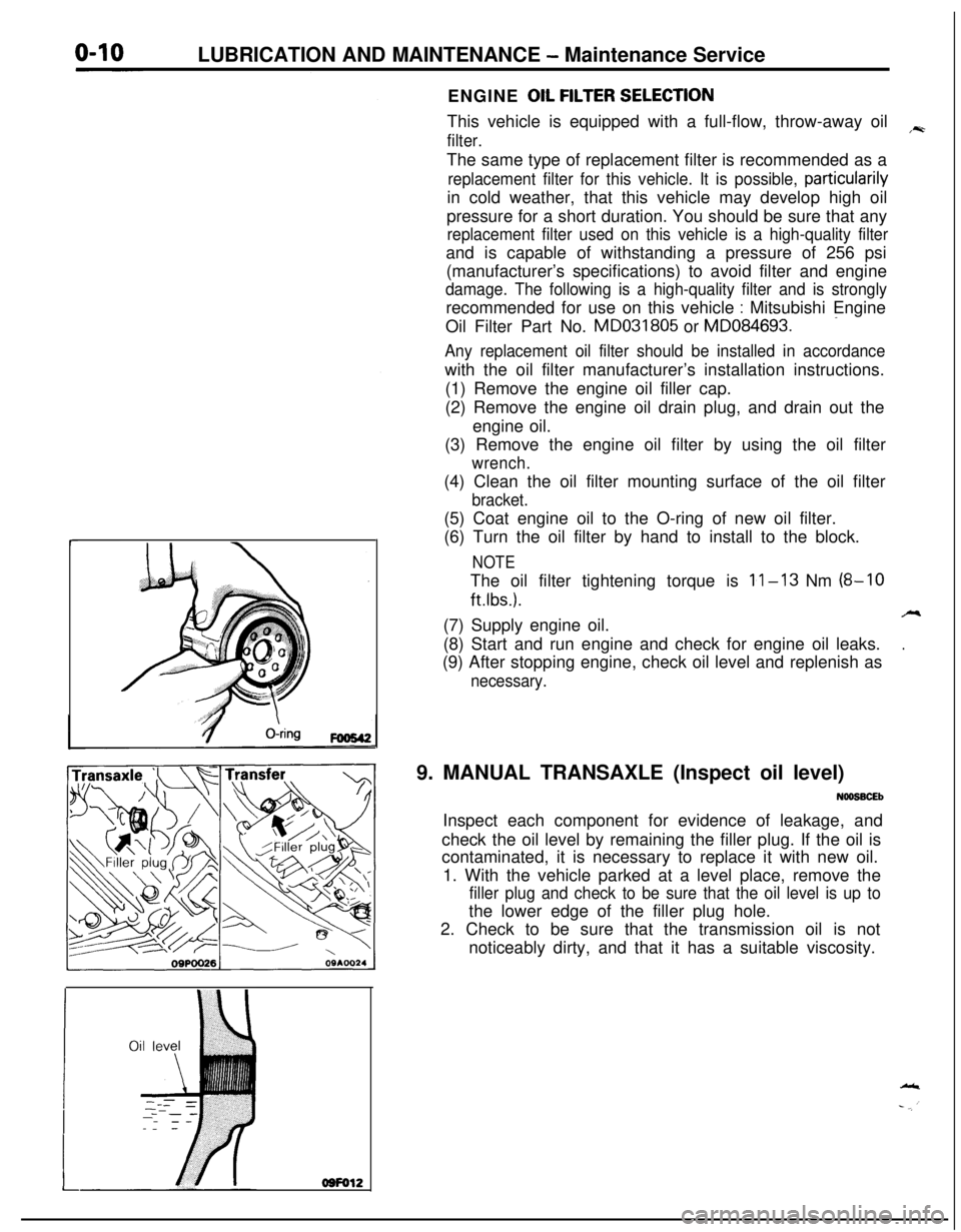
OIL FtLTER SELECTtONThis vehicle is equipped with a full-flow, throw-away oil
,~
filter.The same type of replacement filter is recommended as a
replacement filter for this vehicle. It is possible, particularilyin cold weather, that this vehicle may develop high oil
pressure for a short duration. You should be sure that any
replacement filter used on this vehicle is a high-quality filterand is capable of withstanding a pressure of 256 psi
(manufacturer’s specifications) to avoid filter and engine
damage. The following is a high-quality filter and is stronglyrecommended for use on this vehicle
: Mitsubishi Engine
-Oil Filter Part No. MD031805 or MD084693.
Any replacement oil filter should be installed in accordancewith the oil filter manufacturer’s installation instructions.
(1) Remove the engine oil filler cap.
(2) Remove the engine oil drain plug, and drain out the
engine oil.
(3) Remove the engine oil filter by using the oil filter
wrench.(4) Clean the oil filter mounting surface of the oil filter
bracket.(5) Coat engine oil to the O-ring of new oil filter.
(6) Turn the oil filter by hand to install to the block.
NOTEThe oil filter tightening torque is
11-13 Nm (8-10
ftlbs.).A(7) Supply engine oil.
.(8) Start and run engine and check for engine oil leaks.
(9) After stopping engine, check oil level and replenish as
necessary.9. MANUAL TRANSAXLE (Inspect oil level)
NOOSBCEbInspect each component for evidence of leakage, and
check the oil level by remaining the filler plug. If the oil is
contaminated, it is necessary to replace it with new oil.
1. With the vehicle parked at a level place, remove the
filler plug and check to be sure that the oil level is up tothe lower edge of the filler plug hole.
2. Check to be sure that the transmission oil is not
noticeably dirty, and that it has a suitable viscosity.
Page 45 of 1216
LUBRICATION AND MAINTENANCE - Maintenance ServiceO:lllO.AUTOMATIC TRANSAXLE (Inspect fluid
I~~+v~!1. Drive until the fluid temperature reaches the usual
temperature
[70-80°C (160- 18O”F)l.2. Place vehicle on level floor.
3.Move selector lever sequentially to every position to fill
torque converter and hydraulic
circuitwith fluid, then
place lever in“N” Neutral position. This operation is
necessary to be sure that fluid level check is accurate.
4.Before removing dipstick, wipe all dirt from area arounddipstick. Then take out the dipstick and check the
condition of the fluid.
The transaxle should be overhauled under the following
conditions.l If there is a “burning” odor.
l If the fluid color has become noticeably blacker.
l If there is a noticeably great amount of metal
particles in the fluid.
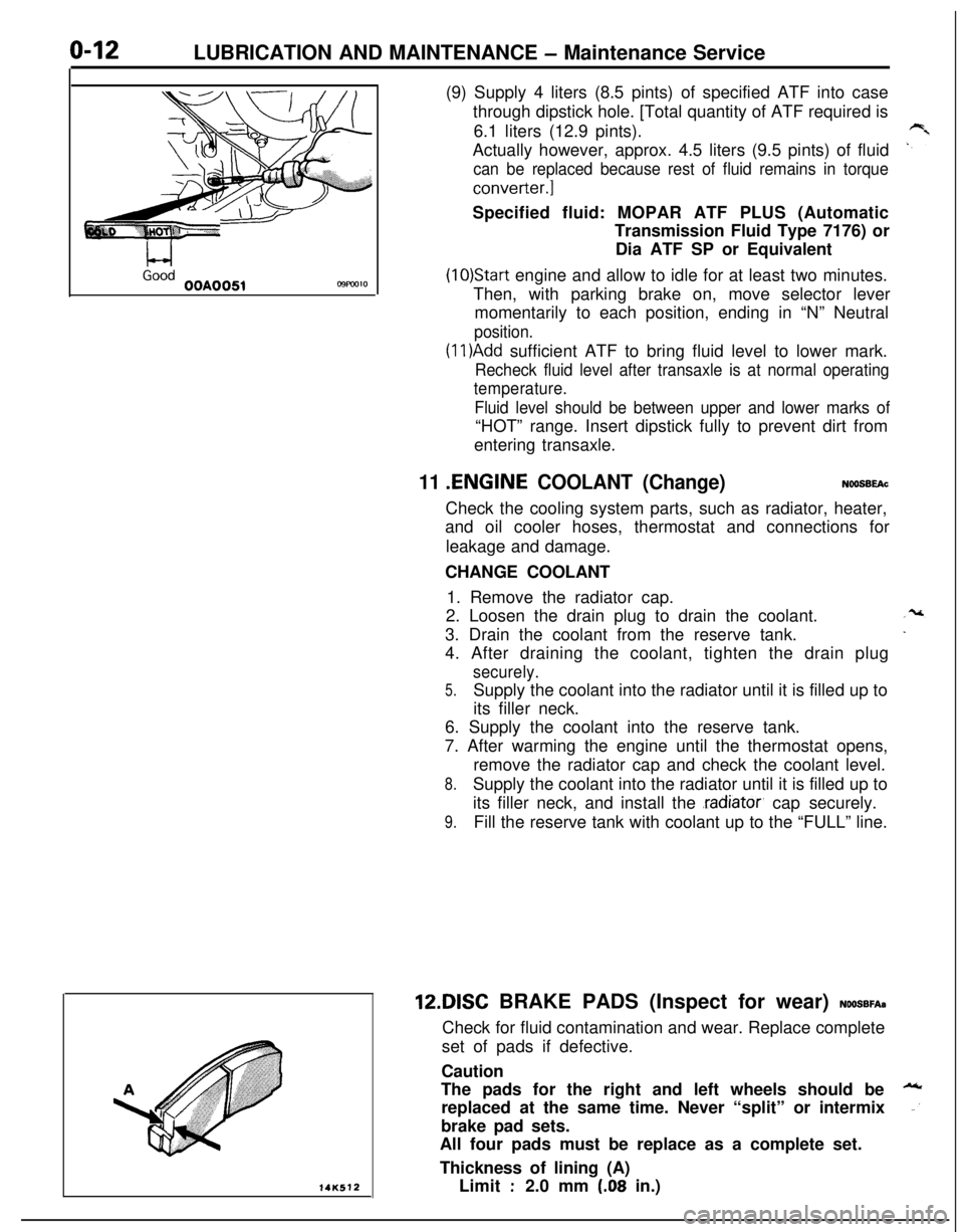
5.Check to see if fluid level is in “HOT” range on dipstick.If fluid level is low, add ATF until level reaches “HOT”
range.Low fluid level can cause a variety of conditions
because it allows pump to take in air along with fluid. Airtrapped in hydraulic circuit forms bubbles which make
fluid spongy. Therefore, pressures will be erratic.
Improper filling can also raise fluid level too high. Whentransaxle has too much fluid, gears churn up foam and
cause same conditions which occur with low fluid level,resulting in accelerated deterioration of ATF.
transmission fluid.
In either case, air bubbles can cause overheating, fluid
oxidation, which can interfere with normal valve, clutch,and servo operation. Foaming can also result in fluid
escaping from transaxle vent where it may be mistakenfor a leak.
6. Be sure to examine fluid on dipstick closely.lO.AUTOMATIC TRANSAXLE (Change fluid)
Drain the fluid and check whether there is any evidence of
contamination.
Replenish with new fluid after the cause of any contamina-tion has been corrected.
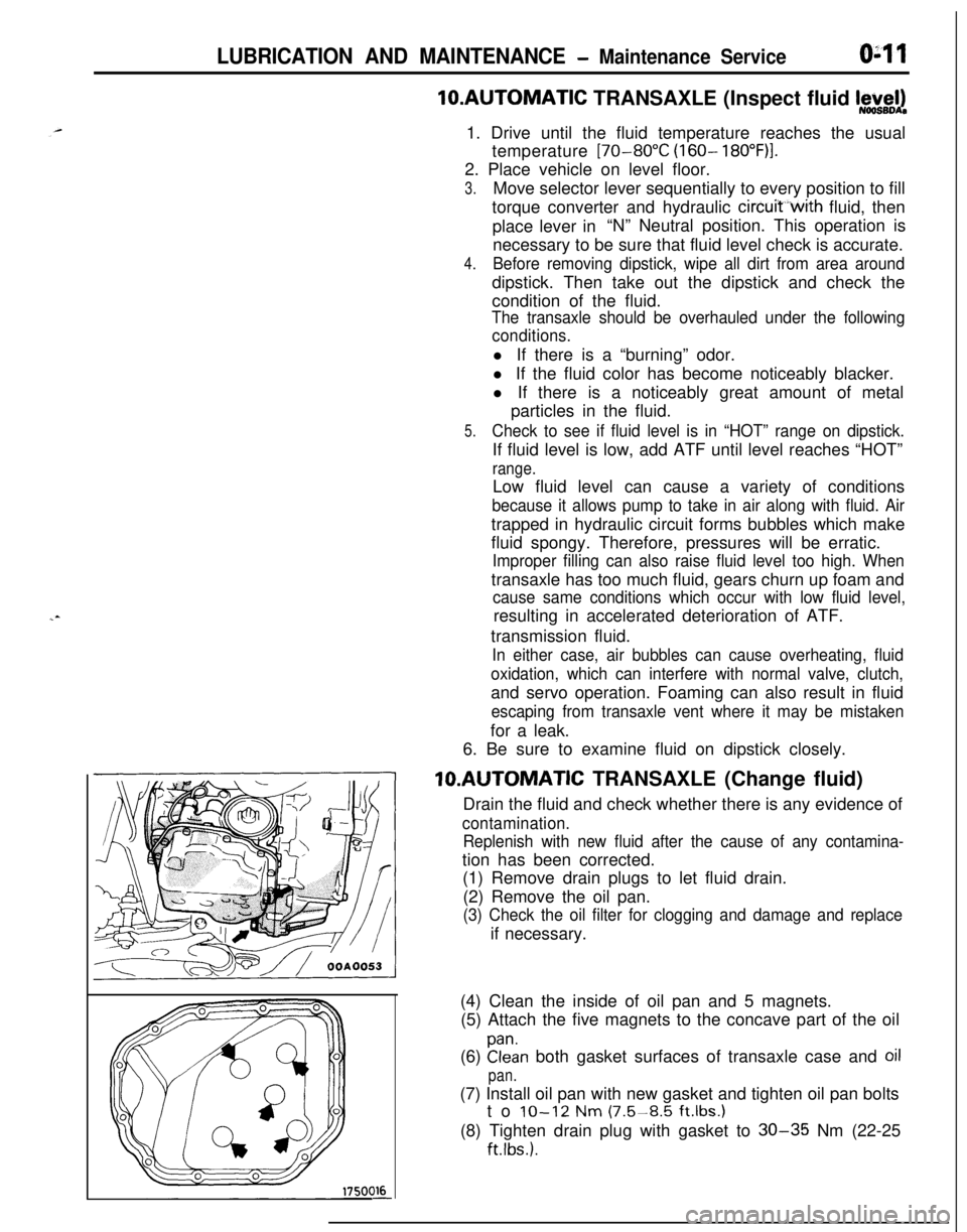
(1) Remove drain plugs to let fluid drain.
(2) Remove the oil pan.
(3) Check the oil filter for clogging and damage and replaceif necessary.
(4) Clean the inside of oil pan and 5 magnets.
(5) Attach the five magnets to the concave part of the oil
(6)
Elan both gasket surfaces of transaxle case and oil
pan.(7) Install oil pan with new gasket and tighten oil pan bolts
to
IO-12 Nm (7.5-8.5 ft.lbs.1(8) Tighten drain plug with gasket to
30-35 Nm (22-25
ftlbs.).
Page 46 of 1216
LUBRICATION AND MAINTENANCE - Maintenance Service
L-4GoodOOA0051C9FW1014K512(9) Supply 4 liters (8.5 pints) of specified ATF into case
through dipstick hole. [Total quantity of ATF required is
6.1 liters (12.9 pints).
Actually however, approx. 4.5 liters (9.5 pints) of fluid
can be replaced because rest of fluid remains in torque
converter.]Specified fluid: MOPAR ATF PLUS (Automatic
Transmission Fluid Type 7176) or
Dia ATF SP or Equivalent
(10)Start engine and allow to idle for at least two minutes.
Then, with parking brake on, move selector lever
momentarily to each position, ending in “N” Neutral
position.
(1 l)Add sufficient ATF to bring fluid level to lower mark.
Recheck fluid level after transaxle is at normal operating
temperature.
Fluid level should be between upper and lower marks of“HOT” range. Insert dipstick fully to prevent dirt from
entering transaxle.
11 .ENGINE COOLANT (Change)NOOSBEAcCheck the cooling system parts, such as radiator, heater,
and oil cooler hoses, thermostat and connections for
leakage and damage.
CHANGE COOLANT
1. Remove the radiator cap.
2. Loosen the drain plug to drain the coolant.
3. Drain the coolant from the reserve tank.
4. After draining the coolant, tighten the drain plug
securely.
5.Supply the coolant into the radiator until it is filled up to
its filler neck.
6. Supply the coolant into the reserve tank.
7. After warming the engine until the thermostat opens,
remove the radiator cap and check the coolant level.
8.Supply the coolant into the radiator until it is filled up to
its filler neck, and install the
.radiator, cap securely.
9.Fill the reserve tank with coolant up to the “FULL” line.12DISC BRAKE PADS (Inspect for wear)
NOOSBFA~Check for fluid contamination and wear. Replace complete
set of pads if defective.
Caution
The pads for the right and left wheels should be
replaced at the same time. Never “split” or intermix
brake pad sets.
All four pads must be replace as a complete set.
Thickness of lining (A)
Limit
:2.0 mm (.08 in.)
Page 47 of 1216
LUBRICATION AND MAINTENANCE - Maintenance Serviceo-13
OOAOlB6
13.BRAKE HOSES (Check for deteriorati.on or
leaks)NwBBnAs
Inspection of brake hoses and tubing should be included inall brake service operations.
The hoses should be checked for:
1. Correct length, severe surface cracking, pulling, scuf-
fing or worn spots. (If the fabric casing of the hoses is
exposed by cracks of abrasion in the rubber hose cover,
the hoses should be replaced. Eventual deterioration ofhose may occur with possible bursting failure.)
2. Faulty installation, casing twisting or interference with
wheel, tire of chassis.
14.BALL JOINT AND STEERING LINKAGE SEALS
(Inspect for grease leaks and damage)
NWSBJAb1. These components, which are permanently lubricated
at the factory, do not require periodic lubrication.
Damaged seals and boots should be replaced to
prevent leakage or contamination of the grease.
2. Inspect the dust cover and boots for proper sealing,
leakage and damage. Replace them if defective.
15.DRIVE SHAFT BOOTS (Inspect for grease leaksand damage)
NWSBJAc1. These components, which are permanently lubricated
at the factory, do not require periodic lubrication.
Damaged boots should be replaced to prevent leakage
or contamination of the grease.
2. Inspect the boots for proper sealing, leakage and
damage. Replace it if defective.
16.REAR AXLE (CONVENTIONAL DIFFERENTIAL)(Inspect oil level)-AWD
NWSBFCa
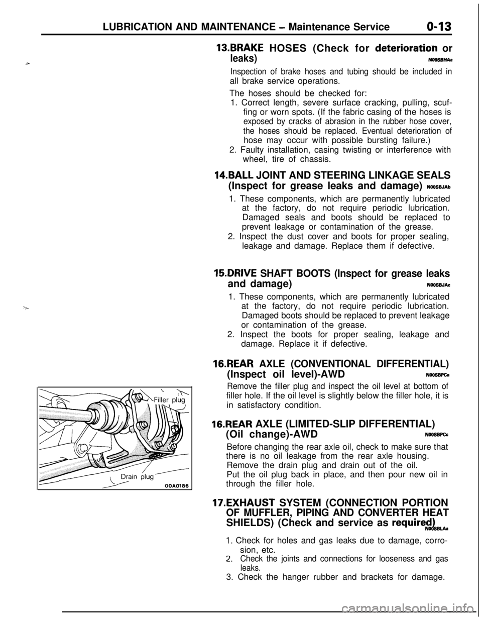
Remove the filler plug and inspect the oil level at bottom offiller hole. If the oil level is slightly below the filler hole, it is
in satisfactory condition.
16.REAR AXLE (LIMITED-SLIP DIFFERENTIAL)
(Oil change)-AWD
N66SBFCcBefore changing the rear axle oil, check to make sure that
there is no oil leakage from the rear axle housing.
Remove the drain plug and drain out of the oil.
Put the oil plug back in place, and then pour new oil in
through the filler hole.
17.EXHAUST SYSTEM (CONNECTION PORTION
OF MUFFLER, PIPING AND CONVERTER HEATSHIELDS) (Check and service as
require$dBu.
1. Check for holes and gas leaks due to damage, corro-
sion, etc.
2.Check the joints and connections for looseness and gas
leaks.3. Check the hanger rubber and brackets for damage.
Page 59 of 1216
FRONT SUSPENSION - Hub and Knuckle2-11Pry bar
Transaxle
llE5&
Huber pin(2)
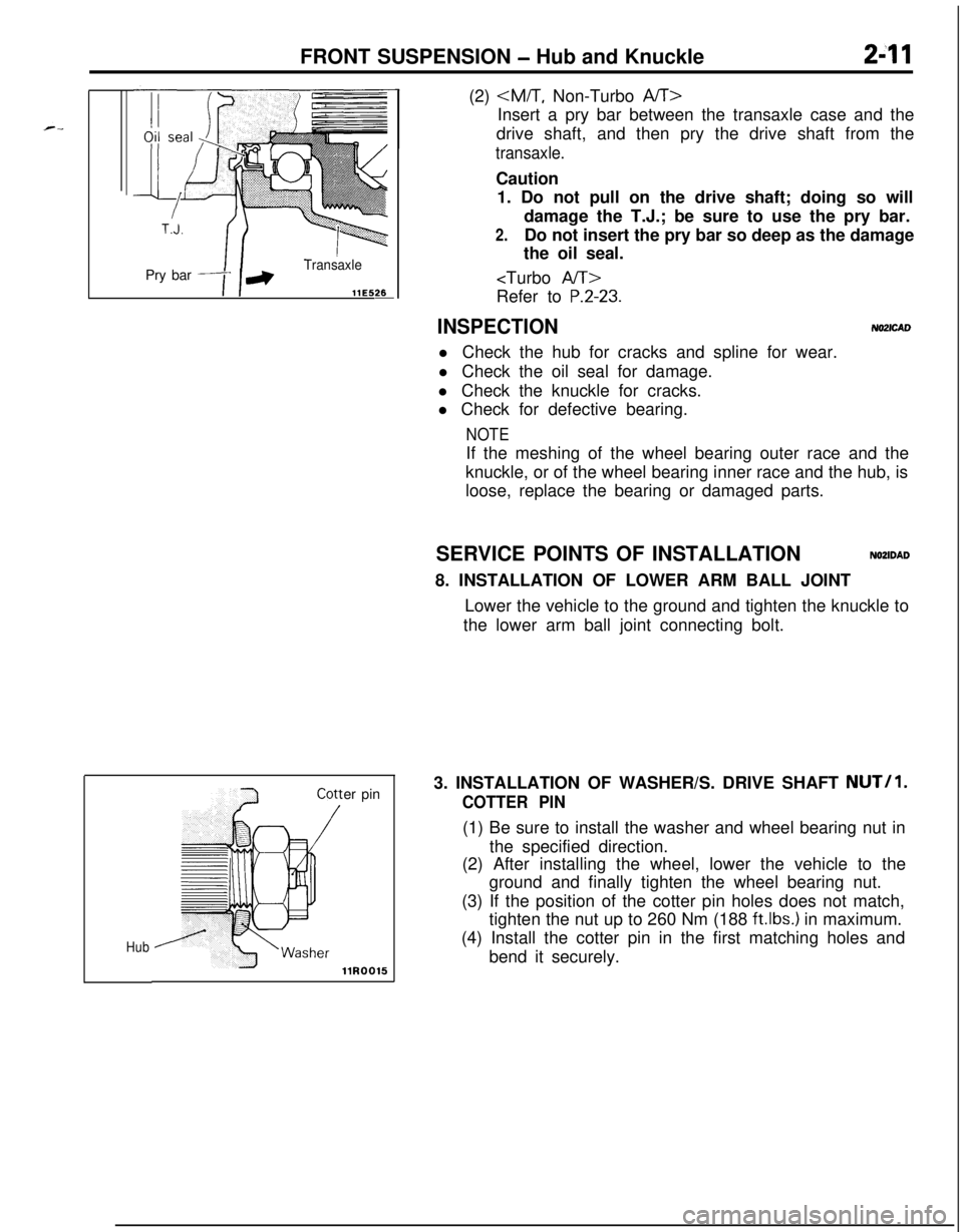
Insert a pry bar between the transaxle case and the
drive shaft, and then pry the drive shaft from the
transaxle.Caution
1. Do not pull on the drive shaft; doing so will
damage the T.J.; be sure to use the pry bar.
2.Do not insert the pry bar so deep as the damage
the oil seal.
P.2-23.
INSPECTIONNO2lCADl Check the hub for cracks and spline for wear.
l Check the oil seal for damage.
l Check the knuckle for cracks.
l Check for defective bearing.
NOTEIf the meshing of the wheel bearing outer race and the
knuckle, or of the wheel bearing inner race and the hub, is
loose, replace the bearing or damaged parts.
SERVICE POINTS OF INSTALLATION
NOZIDAD8. INSTALLATION OF LOWER ARM BALL JOINT
Lower the vehicle to the ground and tighten the knuckle to
the lower arm ball joint connecting bolt.
3. INSTALLATION OF WASHER/S. DRIVE SHAFT
NUT/l.
COTTER PIN(1) Be sure to install the washer and wheel bearing nut in
the specified direction.
(2) After installing the wheel, lower the vehicle to the
ground and finally tighten the wheel bearing nut.
(3) If the position of the cotter pin holes does not match,
tighten the nut up to 260 Nm (188
ftlbs.) in maximum.
(4) Install the cotter pin in the first matching holes and
bend it securely.
Page 61 of 1216
FRONT SUSPENSION - Hub and Knuckle2-13
llA0281
Snar,
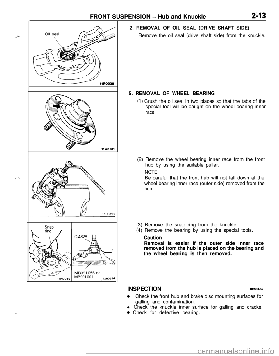
MB991 056 orMB991 001! 12A05542. REMOVAL OF OIL SEAL (DRIVE SHAFT SIDE)
Remove the oil seal (drive shaft side) from the knuckle.
5. REMOVAL OF WHEEL BEARING
(1) Crush the oil seal in two places so that the tabs of the
special tool will be caught on the wheel bearing inner
race.(2) Remove the wheel bearing inner race from the front
hub by using the suitable puller.
NOTEBe careful that the front hub will not fall down at the
wheel bearing inner race (outer side) removed from the
hub.(3) Remove the snap ring from the knuckle.
(4) Remove the bearing by using the special tools.
Caution
Removal is easier if the outer side inner race
removed from the hub is placed on the bearing and
the wheel bearing is then removed.
INSPECTIONNOZffiAkh
0Check the front hub and brake disc mounting surfaces for
galling and contamination.
l Check the knuckle inner surface for galling and cracks.
0 Check for defective bearing.
Page 65 of 1216
FRONT SUSPENSION - Drive Shaft247Pry bar
13E526
12RO426Cotter pin
/
/HubllR0015
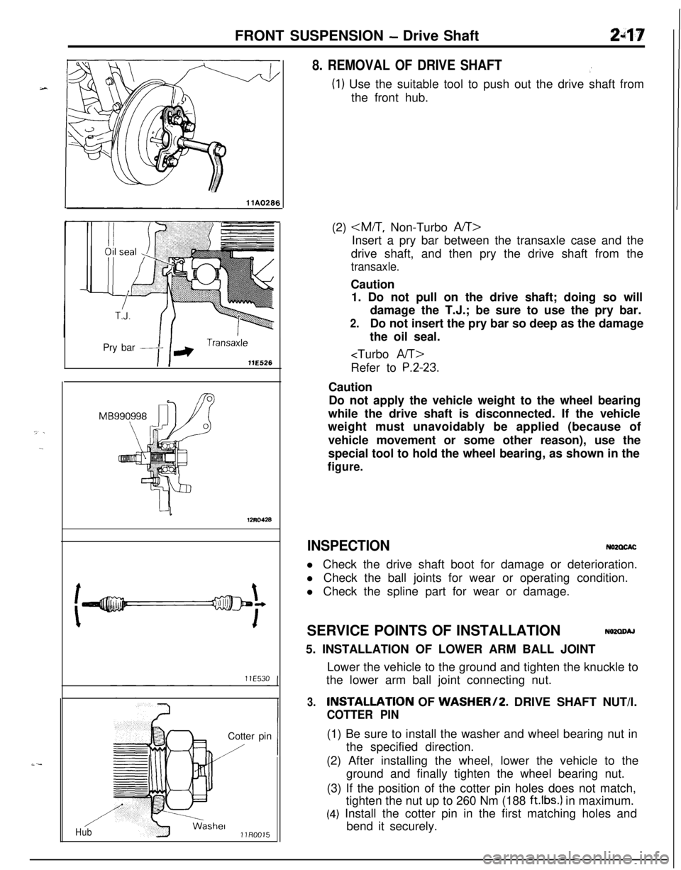
8. REMOVAL OF DRIVE SHAFT.’
(1) Use the suitable tool to push out the drive shaft from
the front hub.
(2)
Insert a pry bar between the transaxle case and the
drive shaft, and then pry the drive shaft from the
transaxle.Caution
1. Do not pull on the drive shaft; doing so will
damage the T.J.; be sure to use the pry bar.
2.Do not insert the pry bar so deep as the damage
the oil seal.
P.2-23.Caution
Do not apply the vehicle weight to the wheel bearing
while the drive shaft is disconnected. If the vehicle
weight must unavoidably be applied (because of
vehicle movement or some other reason), use the
special tool to hold the wheel bearing, as shown in the
figure.
INSPECTIONN62CXACl Check the drive shaft boot for damage or deterioration.
l Check the ball joints for wear or operating condition.
l Check the spline part for wear or damage.
SERVICE POINTS OF INSTALLATION
N62aoAJ5. INSTALLATION OF LOWER ARM BALL JOINT
Lower the vehicle to the ground and tighten the knuckle to
the lower arm ball joint connecting nut.
3.INSTALLATlON OF WASHER/2. DRIVE SHAFT NUT/l.
COTTER PIN(1) Be sure to install the washer and wheel bearing nut in
the specified direction.
(2) After installing the wheel, lower the vehicle to the
ground and finally tighten the wheel bearing nut.
(3) If the position of the cotter pin holes does not match,
tighten the nut up to 260 Nm (188
ft.lbs.) in maximum.
(4) Install the cotter pin in the first matching holes and
bend it securely.