automatic transmission fluid MITSUBISHI ECLIPSE 1991 User Guide
[x] Cancel search | Manufacturer: MITSUBISHI, Model Year: 1991, Model line: ECLIPSE, Model: MITSUBISHI ECLIPSE 1991Pages: 1216, PDF Size: 67.42 MB
Page 862 of 1216
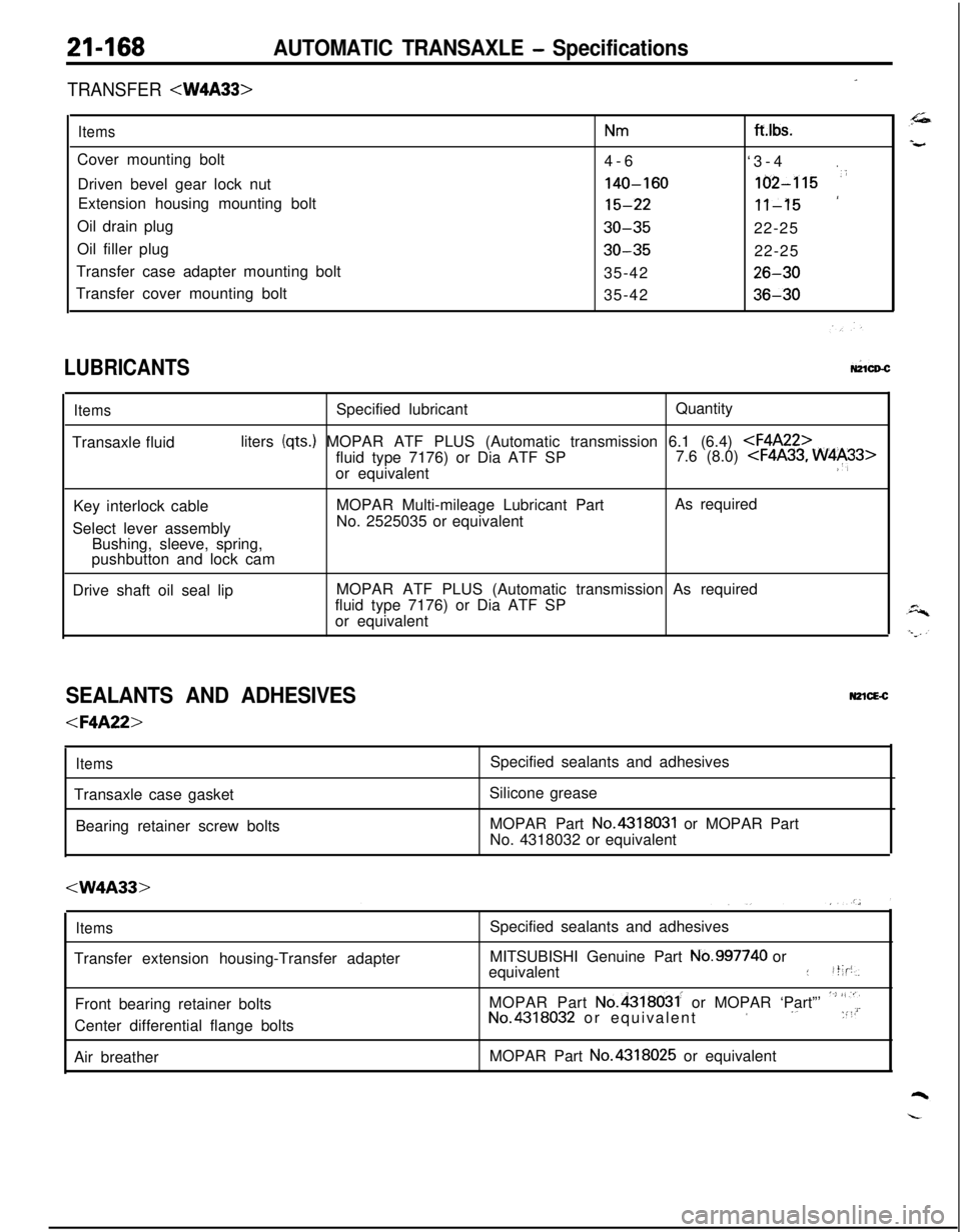
21-168AUTOMATIC TRANSAXLE - Specifications
-TRANSFER
ItemsNmCover mounting bolt
4-6
Driven bevel gear lock nut
140-160Extension housing mounting bolt
15-22Oil drain plug
30-35Oil filler plug
30-35Transfer case adapter mounting bolt
35-42
Transfer cover mounting bolt
35-42ft.lbs.
‘3-4
.
162-115 ‘i
‘11-1522-25
22-25
26-30
36-30
LUBRICANTSW1CD-C
ItemsSpecified lubricantQuantity
Transaxle fluidliters
(qts.) MOPAR ATF PLUS (Automatic transmission 6.1 (6.4)
or equivalent
:‘,Key interlock cableMOPAR Multi-mileage Lubricant PartAs required
Select lever assemblyNo. 2525035 or equivalent
Bushing, sleeve, spring,
pushbutton and lock cam
Drive shaft oil seal lipMOPAR ATF PLUS (Automatic transmission As required
fluid type 7176) or Dia ATF SP
or equivalent
SEALANTS AND ADHESIVESN2lcE-c
ItemsTransaxle case gasket
Bearing retainer screw bolts
Silicone grease
MOPAR Part
No.4318031 or MOPAR Part
No. 4318032 or equivalent
ItemsTransfer extension housing-Transfer adapter
Front bearing retainer bolts
Center differential flange bolts
Air breatherSpecified sealants and adhesives
MITSUBISHI Genuine Part
No.997740 or
equivalent::t;p,
MOPAR Part
No.4318031. or MOPAR ‘Part”’ ‘~’ “,“iNo.4318032 or equivalent’ ‘. :“’MOPAR Part No.4318025 or equivalent
Page 948 of 1216
AUTOMATIC TRANSAXLE - Transaxle Assemblv
Solder
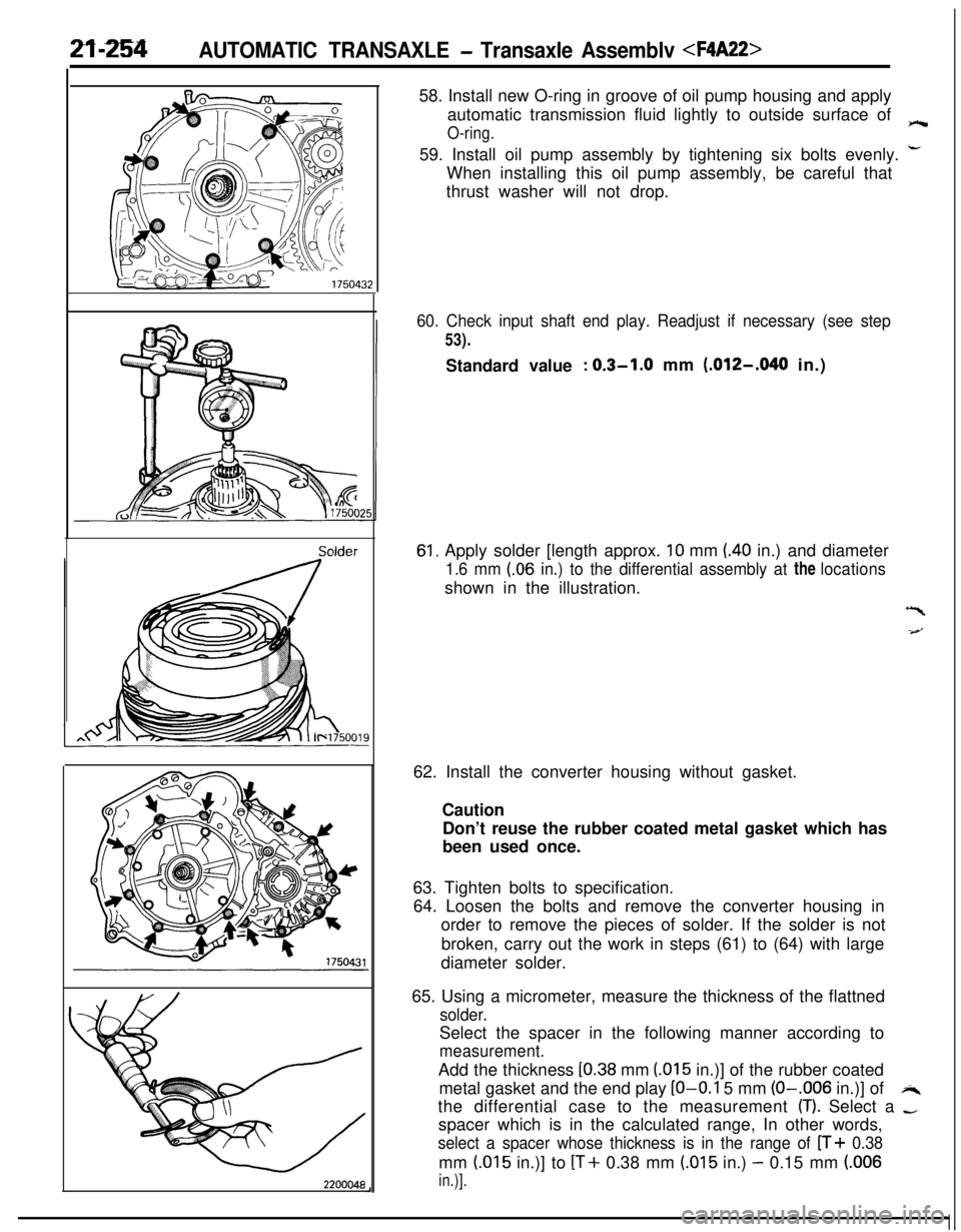
220004858. Install new O-ring in groove of oil pump housing and apply
automatic transmission fluid lightly to outside surface of
O-ring.e59. Install oil pump assembly by tightening six bolts evenly.
i-When installing this oil pump assembly, be careful that
thrust washer will not drop.
60. Check input shaft end play. Readjust if necessary (see step
53).Standard value
: 0.3-1.0 mm (.012-,040 in.)
61, Apply solder [length approx. 10 mm (40 in.) and diameter
1.6 mm (.06 in.) to the differential assembly at the locationsshown in the illustration.
“I
-4--J62. Install the converter housing without gasket.
Caution
Don’t reuse the rubber coated metal gasket which has
been used once.
63. Tighten bolts to specification.
64. Loosen the bolts and remove the converter housing in
order to remove the pieces of solder. If the solder is not
broken, carry out the work in steps (61) to (64) with large
diameter solder.
65. Using a micrometer, measure the thickness of the flattned
solder.Select the spacer in the following manner according to
measurement.Add the thickness
[0.38 mm (015 in.)] of the rubber coated
metal gasket and the end play
LO-O.1 5 mm (O-.006 in.)] ofi4the differential case to the measurement
(T). Select a -spacer which is in the calculated range, In other words,
select a spacer whose thickness is in the range of n+ 0.38mm
(.015 in.)] to [T+ 0.38 mm (.015 in.) - 0.15 mm (.006
in.)].
Page 950 of 1216
21-256AUTOMATIC TRANSAXLE - Transaxle Assembly
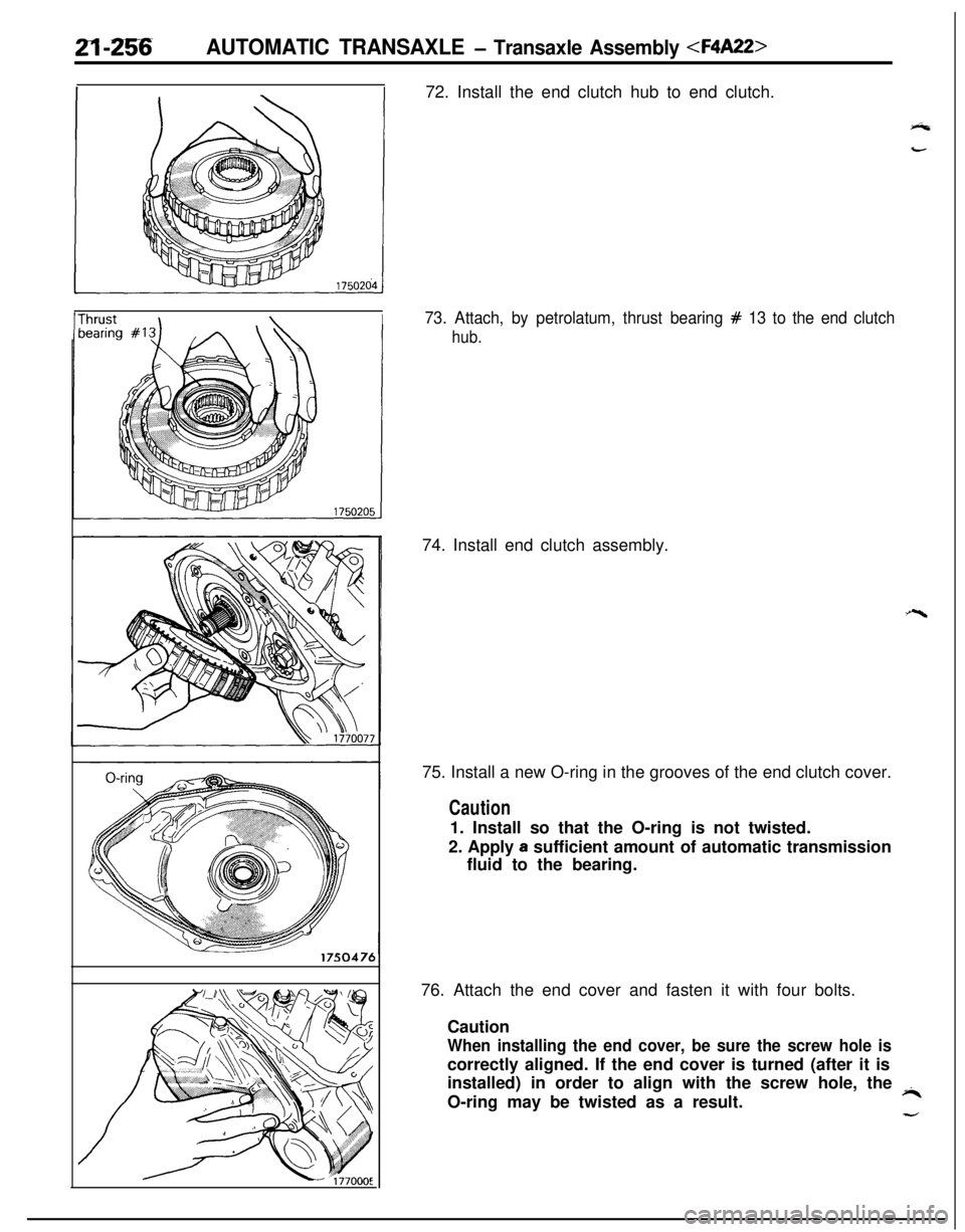
IThrust \\I72. Install the end clutch hub to end clutch.73. Attach, by petrolatum, thrust bearing # 13 to the end clutch
hub.74. Install end clutch assembly.
75. Install a new O-ring in the grooves of the end clutch cover.
Caution1. Install so that the O-ring is not twisted.
2. Apply
a sufficient amount of automatic transmission
fluid to the bearing.
76. Attach the end cover and fasten it with four bolts.
Caution
When installing the end cover, be sure the screw hole iscorrectly aligned. If the end cover is turned (after it is
installed) in order to align with the screw hole, the
iiO-ring may be twisted as a result.
d
Page 964 of 1216

-m-m AUTOMATIC TRANSAXLE -Transaxle Assembly
DISASSEMBLYN21WMCaution
%T1. Since the automatic transaxle is made of particularly
~_,high precision parts, be very careful when handling
them during disassembly and reassembly so that they
are not scratched.
2. Spread a rubber mat on the workbench and keep it
clean.3. Do not use cotton gloves or cloth rags during dis-
assembly. If they are needed, use nylon cloth or paper
towels.
4. Clean all disassembled parts. Clean metal
parts with
normal cleanser and completely dry with air.
5. Clean the clutch disc, resin thrust plate and rubber
parts with ATF (automatic transmission fluid) and do
not get any dirt on them.
6. If the transaxle itself is damaged, disassemble and
clean the cooler system also.
1. Remove the torque converter.
2. Mount the dial gauge on the transaxle case and measure
the end play of the input shaft.
3. Remove the brackets.
4. Remove the oil level gauge and oil level gauge guide.
1:5. Remove the pulse generator A and B.
6.First remove the manual control lever and then remove theinhibitor switch.
7. Remove the speedometer driven gear assembly.
Page 992 of 1216
21-298 AUTOMATIC TRANSAXLE - Transaxle Assembly
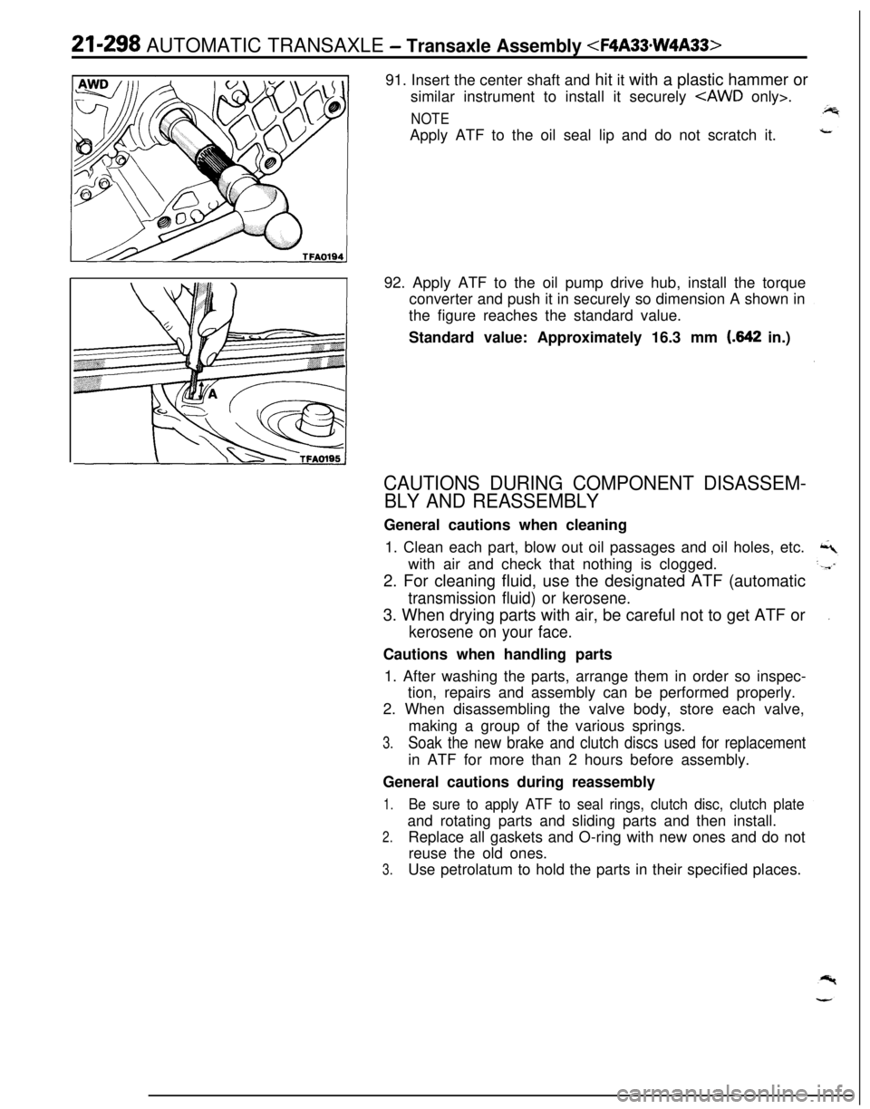
similar instrument to install it securely
NOTEApply ATF to the oil seal lip and do not scratch it.
92. Apply ATF to the oil pump drive hub, install the torque
converter and push it in securely so dimension A shown in
the figure reaches the standard value.
Standard value: Approximately 16.3 mm
(.642 in.)
CAUTIONS DURING COMPONENT DISASSEM-
BLY AND REASSEMBLYGeneral cautions when cleaning
1. Clean each part, blow out oil passages and oil holes, etc.
with air and check that nothing is clogged.
2. For cleaning fluid, use the designated ATF (automatic
transmission fluid) or kerosene.3. When drying parts with air, be careful not to get ATF or
kerosene on your face.Cautions when handling parts
1. After washing the parts, arrange them in order so inspec-
tion, repairs and assembly can be performed properly.
2. When disassembling the valve body, store each valve,
making a group of the various springs.
3.Soak the new brake and clutch discs used for replacementin ATF for more than 2 hours before assembly.
General cautions during reassembly
1.Be sure to apply ATF to seal rings, clutch disc, clutch plateand rotating parts and sliding parts and then install.
2.Replace all gaskets and O-ring with new ones and do not
reuse the old ones.
3.Use petrolatum to hold the parts in their specified places.
Page 997 of 1216
AUTOMATIC TRANSAXLE - Front Clutch Assemblv21-303
1750266
MD998337
\
1750264
/TFA0498Clutch
reactior
TFA0424
i
269
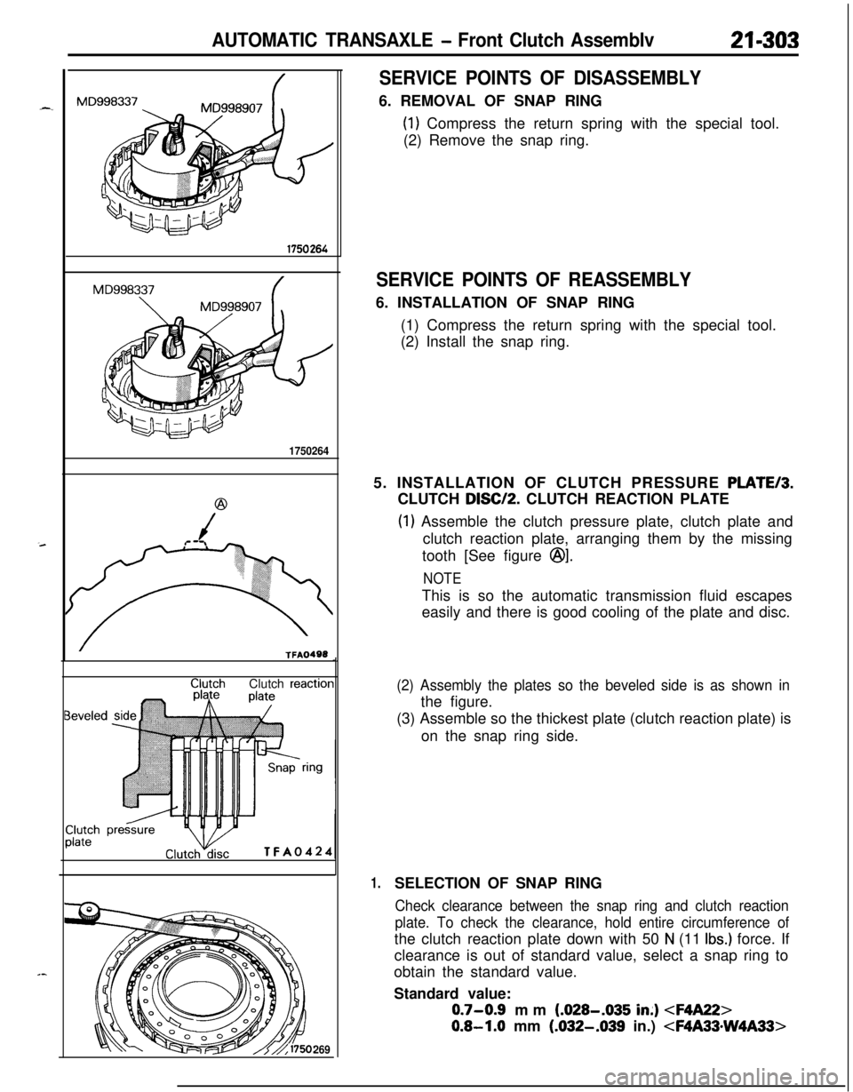
SERVICE POINTS OF DISASSEMBLY6. REMOVAL OF SNAP RING
(1) Compress the return spring with the special tool.
(2) Remove the snap ring.
SERVICE POINTS OF REASSEMBLY6. INSTALLATION OF SNAP RING
(1) Compress the return spring with the special tool.
(2) Install the snap ring.
5. INSTALLATION OF CLUTCH PRESSURE
PLATE/3.CLUTCH
DISC/P. CLUTCH REACTION PLATE
(1) Assemble the clutch pressure plate, clutch plate and
clutch reaction plate, arranging them by the missing
tooth [See figure
@I.
NOTEThis is so the automatic transmission fluid escapes
easily and there is good cooling of the plate and disc.
(2) Assembly the plates so the beveled side is as shown inthe figure.
(3) Assemble so the thickest plate (clutch reaction plate) is
on the snap ring side.
1.SELECTION OF SNAP RING
Check clearance between the snap ring and clutch reaction
plate. To check the clearance, hold entire circumference ofthe clutch reaction plate down with 50
N (11 Ibs.) force. If
clearance is out of standard value, select a snap ring to
obtain the standard value.
Standard value:
0.7-0.9 mm (.028-.035 in;)
0.8-1.0 mm (.032-.039 in.)
Page 1002 of 1216
21-308 AUTOMATIC TRANSAXLE - Rear Clutch Assembly
@
/
(
TFAO240SERVICE POINTS OF
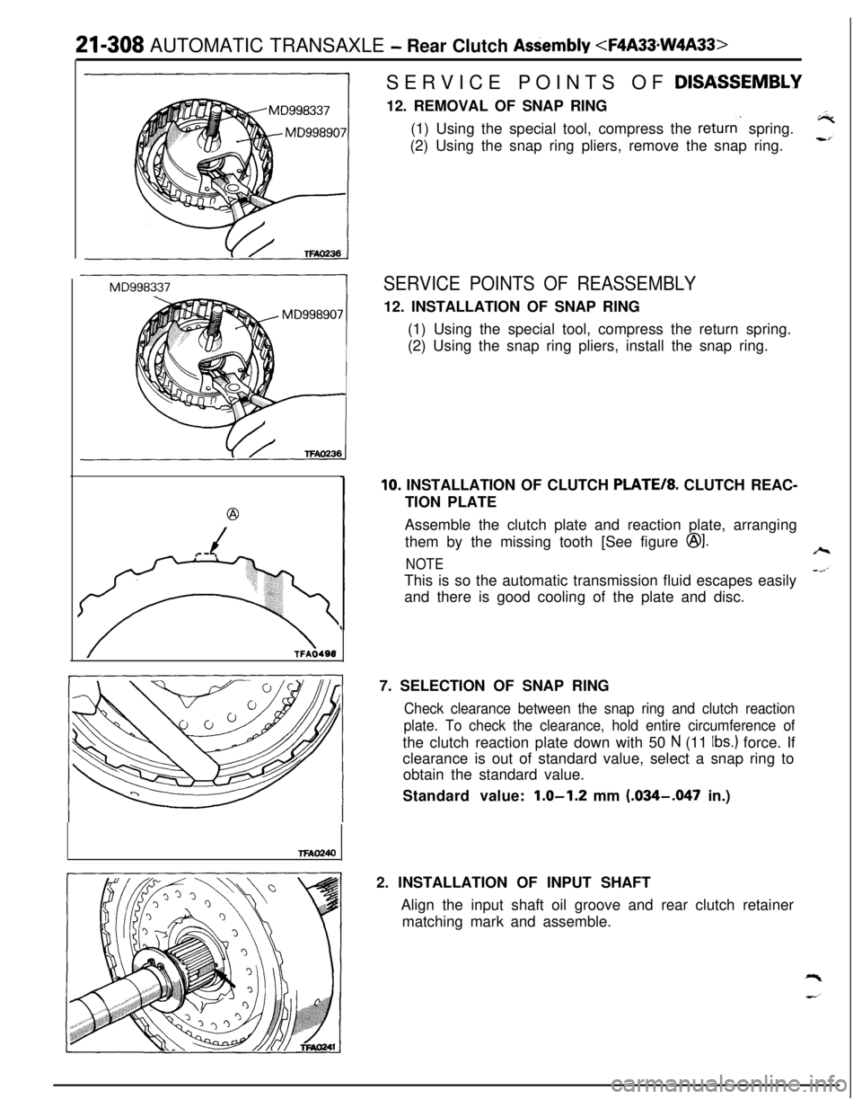
DISASSEM.BLY12. REMOVAL OF SNAP RING
(1) Using the special tool, compress the
returns spring.
(2) Using the snap ring pliers, remove the snap ring.
SERVICE POINTS OF REASSEMBLY12. INSTALLATION OF SNAP RING
(1) Using the special tool, compress the return spring.
(2) Using the snap ring pliers, install the snap ring.
10. INSTALLATION OF CLUTCH PLATE/*. CLUTCH REAC-
TION PLATE
Assemble the clutch plate and reaction plate, arranging
them by the missing tooth [See figure
@I.
NOTEThis is so the automatic transmission fluid escapes easily
and there is good cooling of the plate and disc.
7. SELECTION OF SNAP RING
Check clearance between the snap ring and clutch reaction
plate. To check the clearance, hold entire circumference ofthe clutch reaction plate down with 50
N (11 Ibs.) force. If
clearance is out of standard value, select a snap ring to
obtain the standard value.
Standard value:
1.0-1.2 mm (.034-.047 in.)
2. INSTALLATION OF INPUT SHAFT
Align the input shaft oil groove and rear clutch retainer
matching mark and assemble.