fuse MITSUBISHI ECLIPSE 1991 Service Manual
[x] Cancel search | Manufacturer: MITSUBISHI, Model Year: 1991, Model line: ECLIPSE, Model: MITSUBISHI ECLIPSE 1991Pages: 1216, PDF Size: 67.42 MB
Page 16 of 1216
16INTRODUCTION AND MASTER TROUBLESHOOTING - Precautions before Service
Cl6362
OOYSssOOV833
10A15A
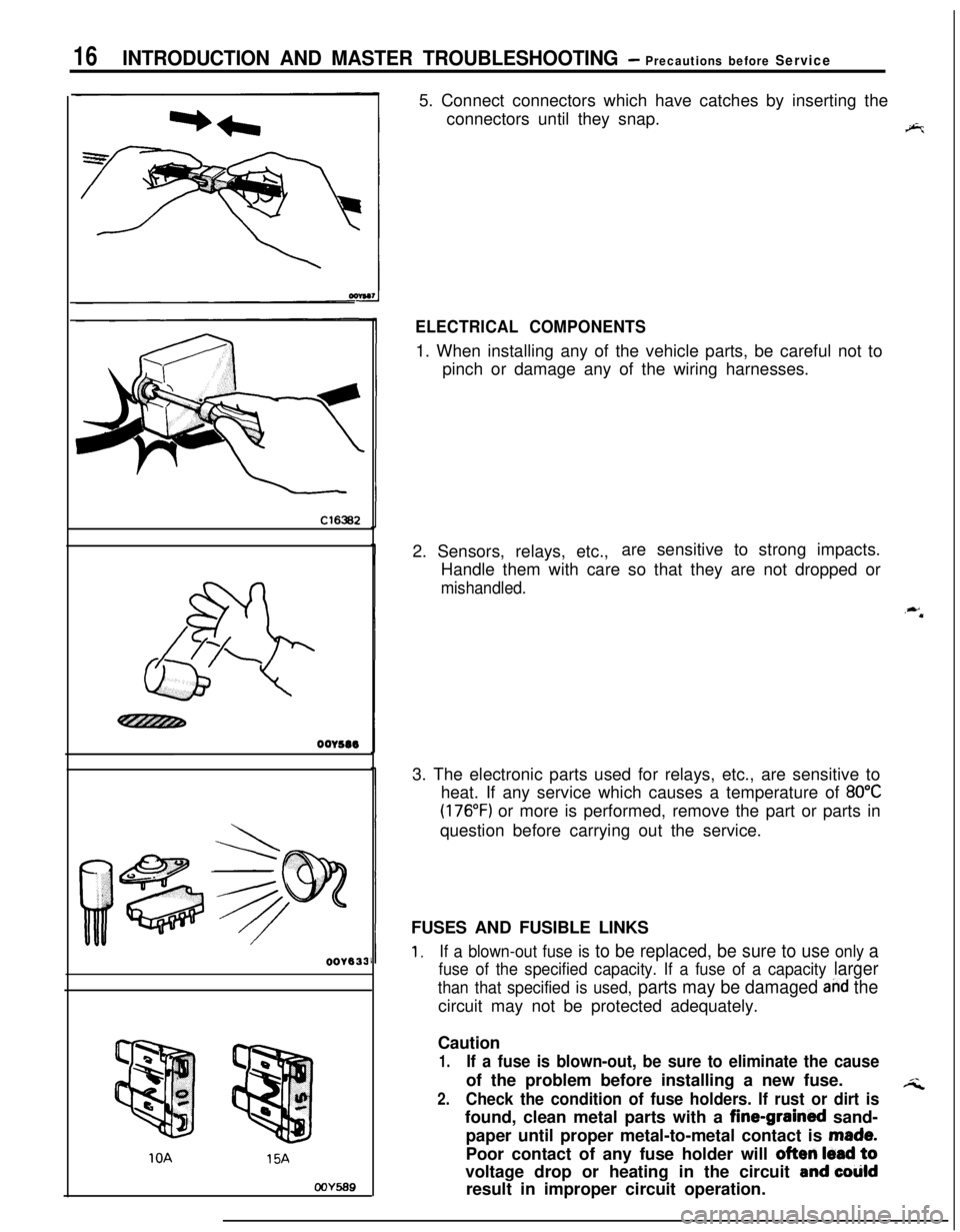
COY5695. Connect connectors which have catches by inserting the
connectors until they snap.
9%
ELECTRICAL COMPONENTS1. When installing any of the vehicle parts, be careful not to
pinch or damage any of the wiring harnesses.
2. Sensors, relays, etc.,are sensitive to strong impacts.
Handle them with care so that they are not dropped or
mishandled.
,**3. The electronic parts used for relays, etc., are sensitive to
heat. If any service which causes a temperature of
80°C
(176°F) or more is performed, remove the part or parts in
question before carrying out the service.
FUSES AND FUSIBLE LINKS
1.If a blown-out fuse is to be replaced, be sure to use only a
fuse of the specified capacity. If a fuse of a capacity larger
than that specified is used, parts may be damaged and thecircuit may not be protected adequately.
Caution
1.If a fuse is blown-out, be sure to eliminate the causeof the problem before installing a new fuse.
;i2.Check the condition of fuse holders. If rust or dirt isfound, clean metal parts with a fine-grained sand-
paper until proper metal-to-metal contact is
made.Poor contact of any fuse holder will
often lead tovoltage drop or heating in the circuit
and colildresult in improper circuit operation.
Page 17 of 1216
INTRODUCTION AND MASTER TROUBLESHOOTING - Precautions before Sew&e‘37
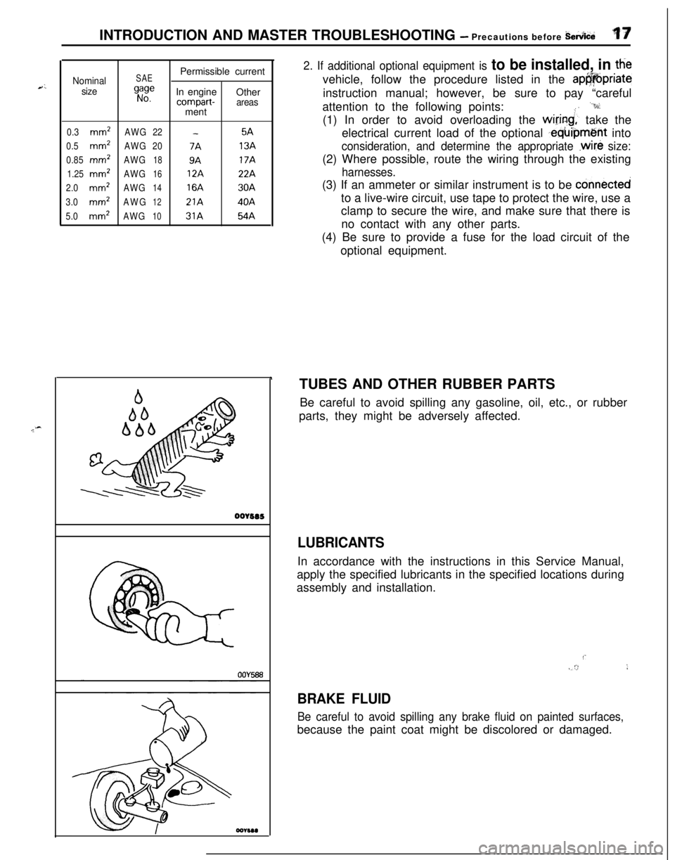
Nominal
sizeSAE
gi:ePermissible current
In engine
Othercompart-areasment
0.3mm2AWG22-5A
0.5
mm2AWG207A13A
0.85
mm’AWG189A17A
1.25
mm2AWG1612A22A
2.0mm2AWG1416A30A
3.0mm’AWG1221A40A
5.0mm2AWG1031A54A
r ‘.
oorsas
2. If additional optional equipment is to be installed, in ttievehicle, follow the procedure listed in the
ap@@priateinstruction manual; however, be sure to pay “careful
attention to the following points:
“9:(1) In order to avoid overloading the
wiring;’ take the
electrical current load of the optional
,equipment into
consideration, and determine the appropriate .wire size:(2) Where possible, route the wiring through the existing
harnesses.(3) If an ammeter or similar instrument is to be
connectedto a live-wire circuit, use tape to protect the wire, use a
clamp to secure the wire, and make sure that there is
no contact with any other parts.
(4) Be sure to provide a fuse for the load circuit of the
optional equipment.
TUBES AND OTHER RUBBER PARTS
Be careful to avoid spilling any gasoline, oil, etc., or rubber
parts, they might be adversely affected.
LUBRICANTSIn accordance with the instructions in this Service Manual,
apply the specified lubricants in the specified locations during
assembly and installation.
!’IV/ :>,I
BRAKE FLUID
Be careful to avoid spilling any brake fluid on painted surfaces,because the paint coat might be discolored or damaged.
Page 150 of 1216
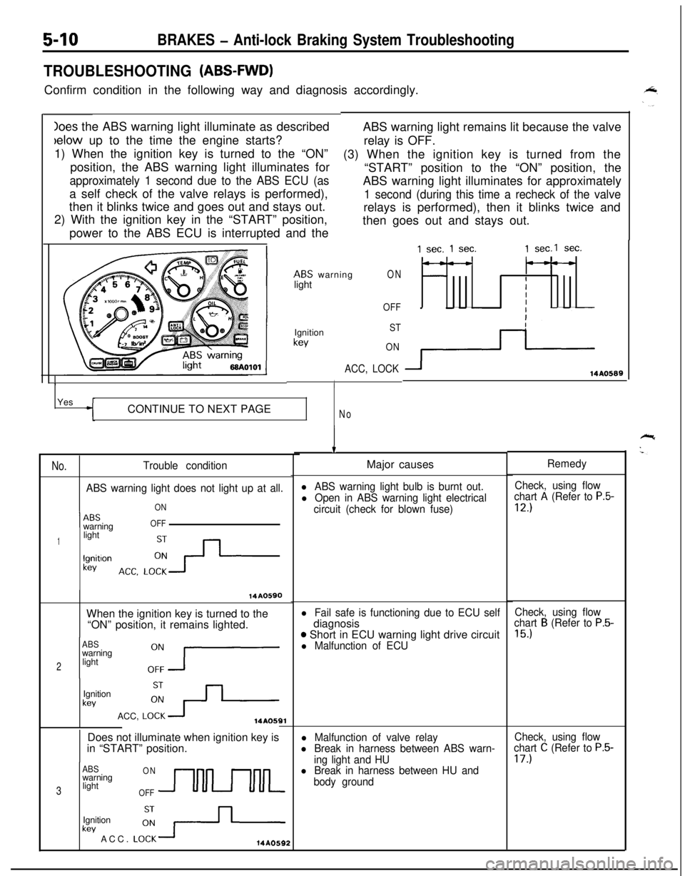
Ioes the ABS warning light illuminate as describedbelow up to the time the engine starts?
1) When the ignition key is turned to the “ON”
position, the ABS warning light illuminates for
approximately 1 second due to the ABS ECU (asa self check of the valve relays is performed),
then it blinks twice and goes out and stays out.
2) With the ignition key in the “START” position,
power to the ABS ECU is interrupted and the
5-10BRAKES - Anti-lock Braking System Troubleshooting
TROUBLESHOOTING (ABS-FWD)Confirm condition in the following way and diagnosis accordingly.
ABS warning light remains lit because the valve
relay is OFF.
(3) When the ignition key is turned from the
“START” position to the “ON” position, the
ABS warning light illuminates for approximately
1 second (during this time a recheck of the valverelays is performed), then it blinks twice and
then goes out and stays out.
ABS warning
lightON
OFF
1Ignition
kev
ST
ON
ACC, LOCK
IYes
CONTINUE TO NEXT PAGE
No
No.Trouble condition
ABS warning light does not light up at all.
ON
1 --ABSwarningOFF
1lightlgnitlon
kev
14A0590When the ignition key is turned to the
“ON” position, it remains lighted.
ABSwarning
2light
Ignition
kevACC,
LO:+14AOSQlDoes not illuminate when ignition key is
in “START” position.
ABSONwarning
3lightOFFUULkev ACC.
LO:-+-Ignition14A0592
1 sec. 1 sec.1 sec.1 sec.
---
IIII
3114AO589
IMajor causes
l ABS warning light bulb is burnt out.Check, using flow
l Open in ABS warning light electricalchart A (Refer to P.5-
circuit (check for blown fuse)12.)
l Fail safe is functioning due to ECU selfdiagnosis
o Short in ECU warning light drive circuitl Malfunction of ECU
l Malfunction of valve relayl Break in harness between ABS warn-
ing light and HU
l Break in harness between HU and
body groundRemedy
Check, using flow
chart
B (Refer to P.5-
15.)
Check, using flow
chart C (Refer to P.5-17.)
Page 152 of 1216
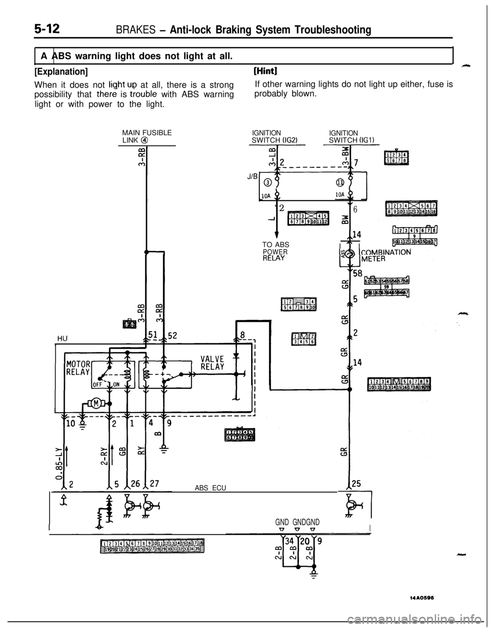
possibility that there is trouble with ABS warning
light or with power to the light.probably blown.
MAIN FUSIBLE
LINK @
5-12BRAKES - Anti-lock Braking System TroubleshootingA ABS warning light does not light at all.
I_
[Explanation][Hint]When it does not
liuht ULI at all, there is a strongIf other warning lights do not light up either, fuse is
IGNITIONSWITCH (IG2)IGNITIONSWITCH (IGl)
10A +,
“2.I6
-1z
v,,14TO ABS
I
” IPOWERIs&h ICOMBINAT~~N
ABS ECU
IGND GNDGNDv v vI
-14AO596
Page 153 of 1216
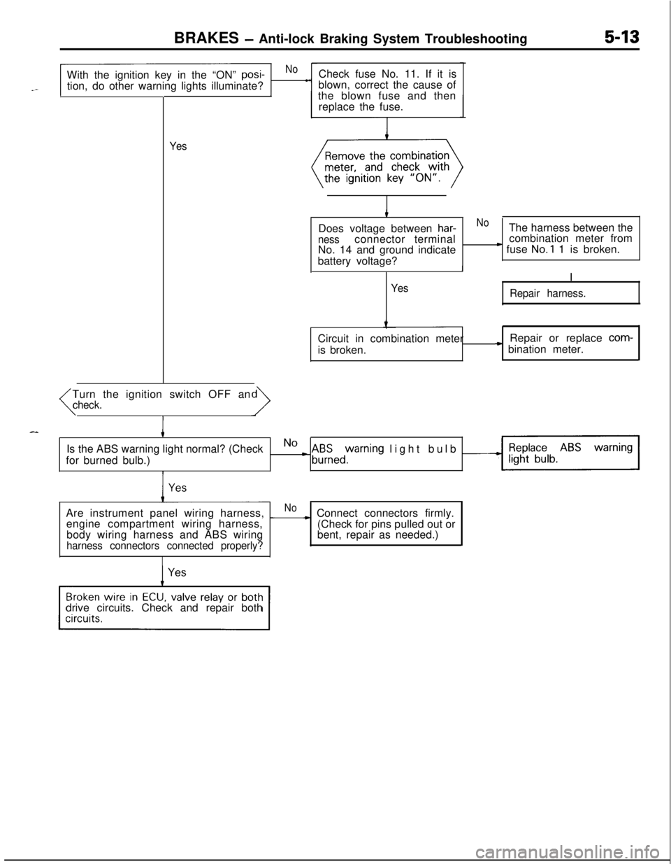
BRAKES - Anti-lock Braking System Troubleshooting5-13With the ignition key in the “ON”
posi-Nol
tion, do other warning lights illuminate?
II
YesCheck fuse No. 11. If it is
blown, correct the cause of
the blown fuse and then
replace the fuse.
Does voltage between
har-NoThe harness between thenessconnector terminalcombination meter from
No. 14 and ground indicate) fuse No.1 1 is broken.
battery voltage?
II
Yes
Repair harness.Circuit in combination meter
is broken.Repair or replace
com-
* bination meter.
Turn the ignition switch OFF an
(check.
IIs the ABS warning light normal? (Check
for burned bulb.)
No L A&zed%rning light bulb -Are instrument panel wiring harness,
_Noengine compartment wiring harness,~ Connect connectors firmly.
(Check for pins pulled out or
bent, repair as needed.) body wiring harness and ABS wiring
harness connectors connected properly?drive circuits. Check and repair both
Page 156 of 1216
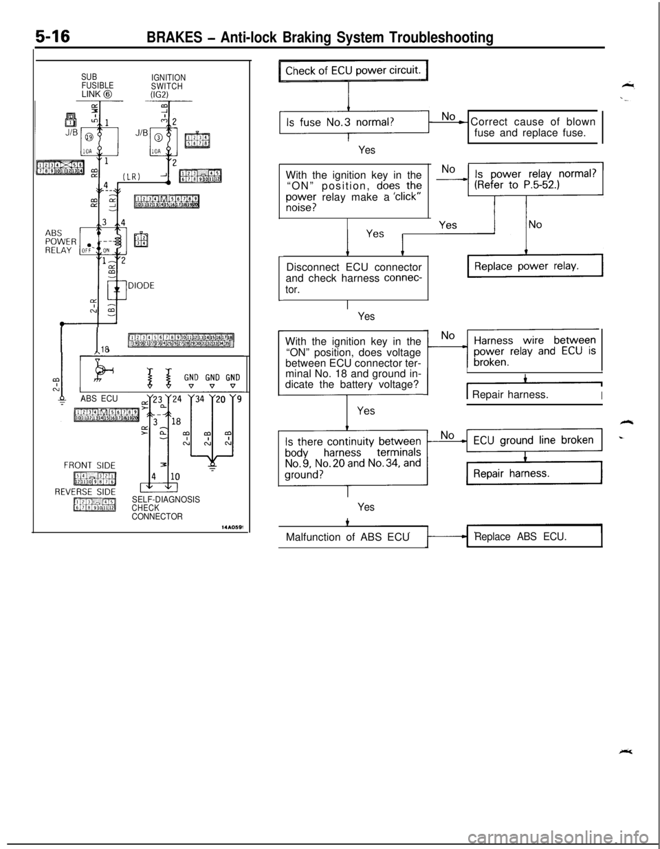
5-16BRAKES - Anti-lock Braking System Troubleshooting
SUB
IGNITION
FUSIBLE
SWITCHLINK
@W.2)
I I18
ABS ECU9
SELF-DIAGNOSISCHECKCONNECTOR
No - Correct cause of blown
fuse and replace fuse.
YesWith the ignition key in the
“ON” position,
does ,thf
E;;;; relay make a click
’ Yes ’Disconnect ECU connector
and check harness
connec-
tor.
YesWith the ignition key in the
“ON” position, does voltage
between ECU connector ter-
minal No. 18 and ground in-
dicate the battery voltage?
---j-z-
III
I -11 Repair harness.I
YesMalfunction of ABS ECU
Replace ABS ECU.
Page 165 of 1216
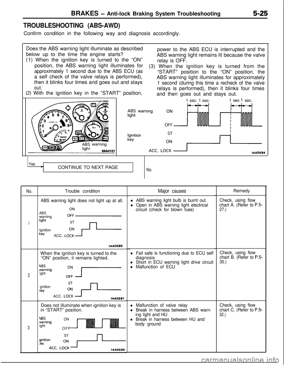
BRAKES - Anti-lock Braking System Troubleshooting5-25
TROUBLESHOOTING (ABS-AWD)Confirm condition in the following way and diagnosis accordingly.
C
F
>oes the ABS warning light illuminate as described
relow up to the time the engine starts?
1) When the ignition key is turned to the “ON”
position, the ABS warning light illuminates for
approximately 1 second due to the ABS ECU (asa self check of the valve relays is performed),
then it blinks four times and goes out and stays
out.power to the ABS ECU is interrupted and the
ABS warning light remains lit because the valve
relay is OFF.
t:2) With the ignition key in the “START” position,(3) When the ignition key is turned from the
“START” position to the “ON” position, the
ABS warning light illuminates for approximately
1 second (during this time a recheck of the valverelays is performed), then it blinks four times
and then goes out and stays out.IO1
-1 sec. 1 sec.1
sec.1 sec.
14AO594
YesCONTINUE TO NEXT PAGE
No
No.
1
2
3
Trouble condition
ABS warning light does not light up at all.
ABSwarninglightOFFIgnitionkey
ACC.
LO;-+
14AOSSOWhen the ignition key is turned to the
“ON” position, it remains lighted.
4BSNamingight
0:7gnition
wACC.
LO:+14A0591Does not illuminate when ignition key is
in “START” position.
4BSNamingightONOFF
14A0595
Major causes
l ABS warning light bulb is burnt out.
l Open in ABS warning light electrical
circuit (check for blown fuse)
l Fail safe is functioning due to ECU self
diagnosis
l Short in ECU warning light drive circuitl Malfunction of ECU
l Malfunction of valve relay
l Break in harness between ABS warn-
ing light and HU
l Break in harness between HU and
body groundRemedy
Check, using flow
chart A. (Refer to
P.5-27.)
Check, using flow
chart B. (Refer to P.5-30.)
Check, using flow
chart C. (Refer to
P.5-
32.)
Page 167 of 1216
![MITSUBISHI ECLIPSE 1991 Service Manual BRAKES - Anti-lock Braking System Troubleshooting5-27
AABS warning light does not light at all.I-. [Explanation]
When it does not light up at all, there is a strong
possibility that there is trouble w MITSUBISHI ECLIPSE 1991 Service Manual BRAKES - Anti-lock Braking System Troubleshooting5-27
AABS warning light does not light at all.I-. [Explanation]
When it does not light up at all, there is a strong
possibility that there is trouble w](/img/19/57104/w960_57104-166.png)
BRAKES - Anti-lock Braking System Troubleshooting5-27
AABS warning light does not light at all.I-. [Explanation]
When it does not light up at all, there is a strong
possibility that there is trouble with ABS warning
light or with power to the light.
MAIN FUSIBLE
LINK
@
2
c-4
I 1~0~0~fWW-i
m2 ac
HU&,52&8--1
III
IA x A ,c
VALVE "I
RELAYI
1 IRELAY /--+I1 &-I I
\, J,. \ ,I L-1
I-----------A
I I
[Hint]If other warning lights do not light up either, fuse is
probably blown.
IGNITIONIGNITIONSWITCH (IG2)SWITCH (IGI)
10A10A p,
*2\I6-IM"
7,,14112131415161718I 9 I
iE4~oWERI.0(1111211311915116117
#$II;NATION
58
ABS ECU125
GNDGNDT7”
Page 168 of 1216
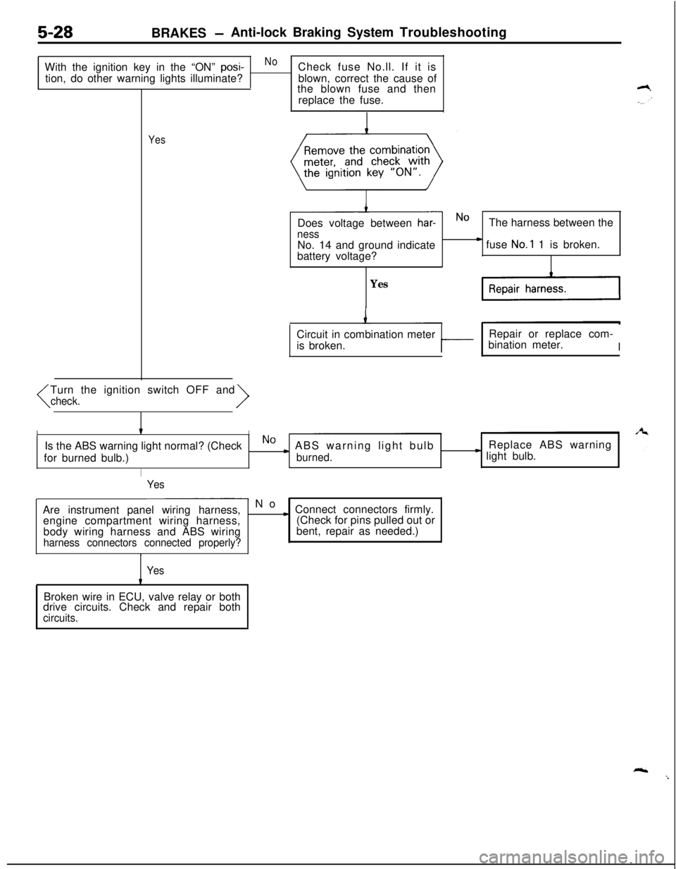
5-28BRAKES -Anti-lock Braking System Troubleshooting
With the ignition key in the “ON”
posi-NoCheck fuse No.ll. If it is
tion, do other warning lights illuminate?blown, correct the cause of
the blown fuse and then
replace the fuse.
YesTurn the ignition switch OFF and
har-NOThe harness between the
nessNo. 14 and ground indicate
battery voltage?) fuse No.1 1 is broken.
YesCircuit in combination meter
is broken.
tRepair or replace com-
bination meter.II
IIIs the ABS warning light normal? (CheckNO) ABS warning light bulbReplace ABS warning
for burned bulb.)
burned.* light bulb.
I
Yes
- No
Are instrument panel wiring harness,
engine compartment wiring harness,
body wiring harness and ABS wiring
harness connectors connected properly?
c Connect connectors firmly.
(Check for pins pulled out or
bent, repair as needed.)
YesBroken wire in ECU, valve relay or both
drive circuits. Check and repair both
circuits.
Page 255 of 1216
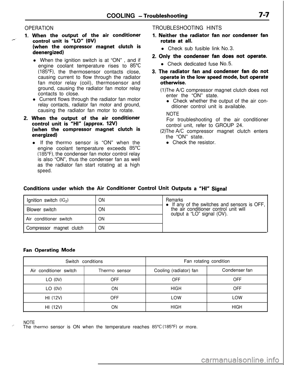
COOLING - Troubleshooting7A7
OPERATION
1. When the output of the air conditioner*--control unit is “LO” (OV)(when the
compressor magnet clutch isdeenergized)
l When the ignition switch is at “ON” , and if
engine coolant temperature rises to
85°C
(185”F), the thermosensor contacts close,
causing current to flow through the radiator
fan motor relay (coil), thermosensor and
ground, causing the radiator fan motor relay
contacts to close.
l Current flows through the radiator fan motor
relay contacts, radiator fan motor and ground,causing the radiator fan motor to rotate.
2. When the output of the air conditioner
control unit is “HI” (approx. 12V)(when the
compressor magnet clutch is
energized)l If the therm0 sensor is “ON” when the
engine coolant temperature exceeds
85°C
(185°F). the condenser fan motor control relay
is also “ON”, thus the condenser fan as well
as the radiator fan start rotating at a high
speed.
TROUBLESHOOTING HINTS
1. Neither the radiator fan nor condenser fanrotate at
all.l Check sub fusible link
No.3.
2. Only the condenser fan does not operate.l Check dedicated fuse
No.5.
3. The radiator fan and condenser fan do notoperate
in the low speed mode, but operateotherwise.
(1)The A/C compressor magnet clutch does not
enter the “ON” state.
l Check whether the output of the air con-
ditioner control unit is available.
NOTEFor troubleshooting of the air conditioner
control unit, refer to GROUP 24.
(2)The A/C compressor magnet clutch enters
the “ON” state.
l Check the resistor.Conditions
under which the Air Conditioner Control Unit Outputs a “HI” Signal
Ignition switch (IG2)
Blower switchAir conditioner switch
Compressor magnet clutch
ON
ON
ON
ON
Remarksl If any of the switches and sensors is OFF,
the air conditioner control unit will
output a “LO” signal (OV).
Fan Operating Mode
Switch conditions
Air conditioner switch
Therm0 sensor
LO
(OV)OFFLO
(OV)ONHI
(12V)OFFHI
(12V)ONFan rotating condition
Cooling (radiator) fanCondenser fan
OFFOFF
HIGHOFF
LOWLOW
HIGHHIGH
NOTE
_-The therm0 sensor is ON when the temperature reaches 85°C (185°F) or more.