center console MITSUBISHI ECLIPSE 1991 Service Manual
[x] Cancel search | Manufacturer: MITSUBISHI, Model Year: 1991, Model line: ECLIPSE, Model: MITSUBISHI ECLIPSE 1991Pages: 1216, PDF Size: 67.42 MB
Page 878 of 1216

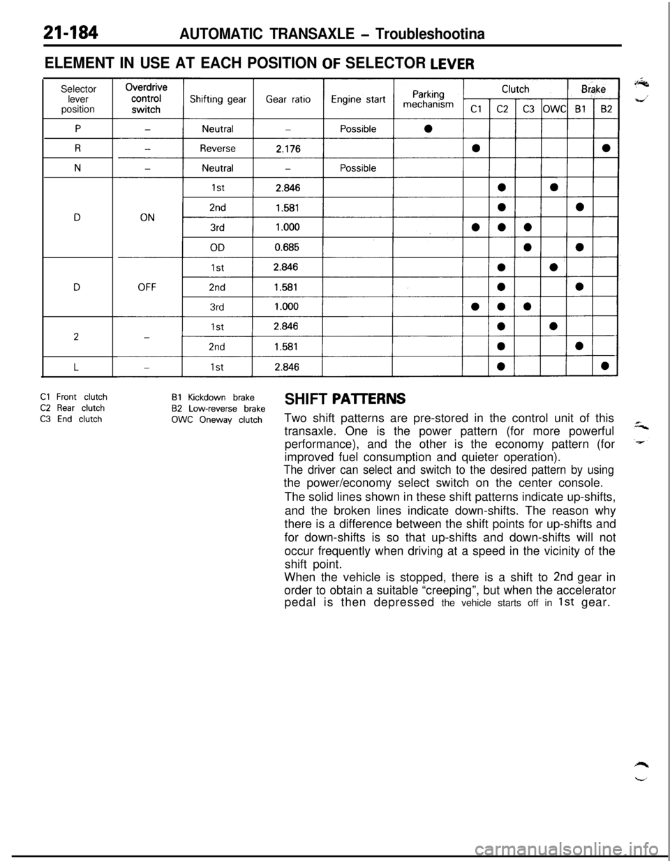
21-184AUTOMATIC TRANSAXLE - TroubleshootinaSelector
lever
position
P
R
N
ELEMENT IN USE AT EACH POSITION OF SELECTOR LEVER
2
LCl
Front clutch
C2 Rear clutch
C3 End clutch
Bl Kickdown brakeSHIFT PAlTERNS82 Low-reverse brake
OWC Oneway clutchTwo shift patterns are pre-stored in the control unit of this
transaxle. One is the power pattern (for more powerful
performance), and the other is the economy pattern (for
improved fuel consumption and quieter operation).
The driver can select and switch to the desired pattern by usingthe power/economy select switch on the center console.
The solid lines shown in these shift patterns indicate up-shifts,
and the broken lines indicate down-shifts. The reason why
there is a difference between the shift points for up-shifts and
for down-shifts is so that up-shifts and down-shifts will not
occur frequently when driving at a speed in the vicinity of the
shift point.
When the vehicle is stopped, there is a shift to
2nd gear in
order to obtain a suitable “creeping”, but when the accelerator
pedal is then depressed the vehicle starts off in
1st gear.
Page 1138 of 1216

23-94BODY - Seat Belt
SEAT BELT
REMOVAL AND INSTALLATION
N23UQBF
/
//35-55 Nm
25-40 ft.lbs.U/16 in. x 25 mm
bolts) ,n(8 x 20 mm
bolts)
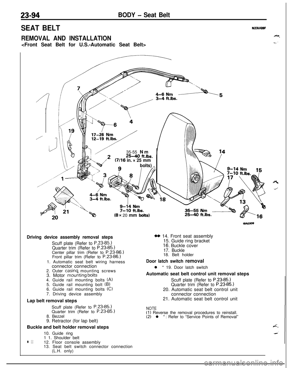
Driving device assembly removal steps
Scuff plate (Refer to P.23-85.1Quarter trim (Refer to P.23-85.)Center pillar trim (Refer to P.23-86.)
Front pillar trim (Refer to P.23-86.)
1. Automatic seat belt wiring harness
connector connection
2. Outer
casinq mounting screws
3. Motor mouriting bolts-4. Guide rail mounting bolts (A)5. Guide rail mounting bolt (B)6. Guide rail mounting bolts (Cl
7. Driving device assembly
Lap belt removal steps
Scuff plate (Refer to P.23-85.)
Quarter trim (Refer to P.23-85
8. Bezzel
9. Retractor (for lap belt)
Buckle and belt holder removal steps
10. Guide ring
l *1 1. Shoulder belt
12. Floor console assembly
13. Seat belt switch connector connection
(L.H. only)
25-4.0 ft.lbs.
w 14. Front seat assembly
15. Guide ring bracket
16. Buckle cover
17. Buckle18. Belt holder
Door latch switch removall * 19. Door latch switch
Automatic seat belt control unit removal steps
Scuff plate (Refer to P.23-85.)Quarter trim (Refer to P.23-85.)20. Automatic seat belt control unit
connector connection
21. Automatic seat belt control unit
NOTE(1) Reverse the removal procedures to reinstall.(2) l * : Refer to “Service Points of Removal”
Page 1175 of 1216

HEATERS AND AIR CONDITIONING - Heater Unit24-31
HEATER UNIT
REMOVAL AND INSTALLATIONN24m-
Pre-removal OperationeDraining of Engine Coolant(Refer to GROUP 7-Service Adjust-ment Procedures.)
@Removal of Floor Console and In-
strument Panel
(Refer to GROUP 23-Floor Consoleand Instrument Panel.)Post-installation Operation
*Supplying of Coolant
(Refer to GROUP 7-Service Adjust-ment Procedures.)
l installation of Floor Console and
Instrument Panel
(Refer to GROUP 23-Floor Consoleand Instrument Panel.)
shower duct>
Jshower duct>
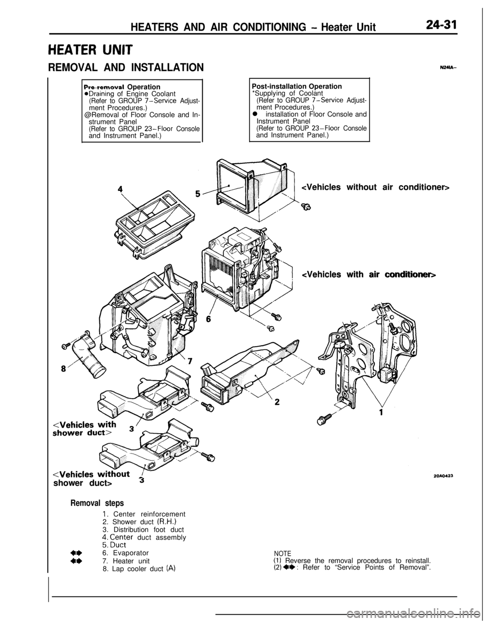
Removal steps
1. Center reinforcement
2. Shower duct (R.H.)
3. Distribution foot duct
;: ;Z;;er duct assembly
:z6. Evaporator
7. Heater unit
8. Lap cooler duct (A)
NOTE(1) Reverse the removal procedures to reinstall.(2) 4* : Refer to “Service Points of Removal”.