cruise control MITSUBISHI ECLIPSE 1991 User Guide
[x] Cancel search | Manufacturer: MITSUBISHI, Model Year: 1991, Model line: ECLIPSE, Model: MITSUBISHI ECLIPSE 1991Pages: 1216, PDF Size: 67.42 MB
Page 455 of 1216
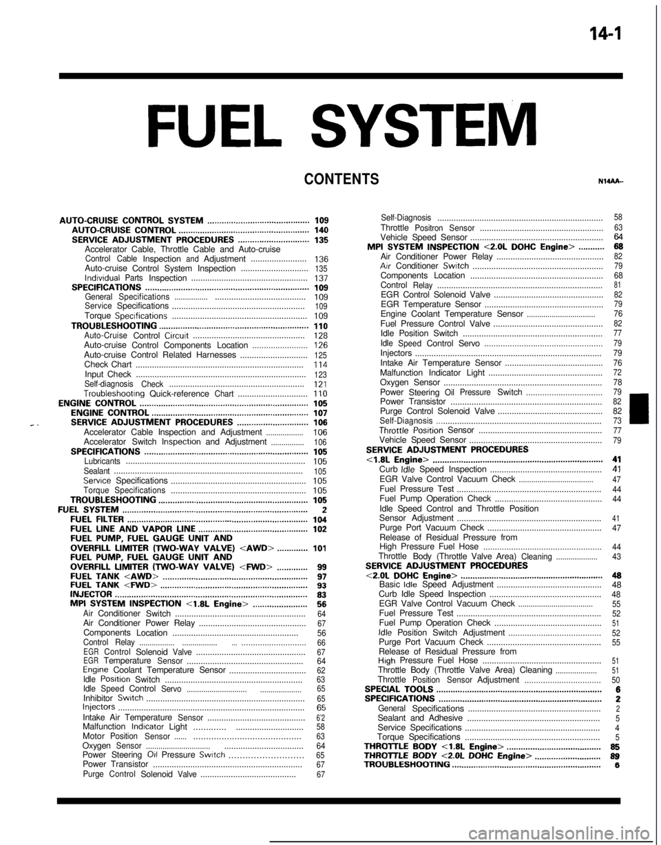
14-IFUEL SYSTEM
CONTENTS
AUTO-CRUISECONTROLSYSTEM...........................................109AUTO-CRUISECONTROL.......................................................140SERVICEADJUSTMENTPROCEDURES..............................135Accelerator Cable, Throttle Cable and Auto-cruise
ControlCableInspectionandAdjustment........................136Auto-cruise
ControlSystemInspection.............................135lndrvrdualPartsInspection..................................................137SPECIFICATIONS.....................................................................109GeneralSpecifications.......................................................109ServiceSpecifications
.........................................................109Torque Specrfications..........................................................109TROUBLESHOOTING...............................................................110Auto-CruiseControlCircurt................................................128Auto-cruise
ControlComponentsLocation........................126Auto-cruise Control Related Harnesses
.............................125Check Chart
........................................................................114Input Check.........................................................................123Self-diagnosis
Check..........................................................121Troubleshootrng
Quick-referenceChart..............................110ENGINECONTROL.......................................................................105ENGINECONTROL..................................................................107--SERVICEADJUSTMENTPROCEDURES..............................106Accelerator Cable Inspection and Adjustment..................106Accelerator Switch Inspectron and Adjustment................106SPECIFICATIONS.....................................................................105Lubricants.............................................................................105Sealant.................................................................................105ServiceSpecifications
..........................................................105TorqueSpecifications..........................................................105TROUBLESHOOTING...............................................................105FUELSYSTEM..............................................................................2FUELFILTER............................................................................104FUELLINEANDVAPORLINE..............................................102FUEL PUMP, FUEL GAUGE UNIT ANDOVERFILL LIMITER(TWO-WAY VALVE)
Switch........................................................64Air Conditioner Power Relay
..............................................67Components
Location......................................................56
ControlRelay
.................................................................66EGRControlSolenoidValve...............................................67EGRTemperatureSensor..................................................64Engine Coolant Temperature Sensor
.................................62IdlePosrtionSwitch
...........................................................63IdleSpeedControlServo
.............................
....................65InhibitorSwitch....................................................................65hjeCtOrS................................................................................65IntakeAirTemperatureSensor..........................................6’2MalfunctionlndtcatorLight
..........................................58MotorPosition
Sensor................................................63OxygenSensor
.................................................................64Power Steering 011 Pressure Swatch...........................65PowerTransistor
................................................................67PurgeControlSolenoidValve.........................................67
Self-Diagnosis.......................................................................
ThrottlePositronSensor.....................................................
Vehicle Speed Sensor.........................................................MPI
SYSTEMINSPECTION<2.0L DOHCEngine>...........Air Conditioner Power Relay..............................................
Arr Conditioner Swatch........................................................
Components Location
.........................................................
Control
Relay.......................................................................
EGR Control Solenoid Valve...............................................
EGR Temperature Sensor
...................................................
Engine Coolant Temperature Sensor
.................................Fuel Pressure Control Valve...............................................
Idle Position Switch
............................................................
Idle
SpeedControlServo...................................................Injectors
................................................................................
Intake Air Temperature Sensor..........................................
Malfunction Indicator Light.................................................
Oxygen Sensor
....................................................................
Power
Steering
OilPressureSwitch.................................Power Transistor
.................................................................
Purge Control Solenoid Valve.............................................
Self-Diaanosis.......................................................................
58
63
2382
79
688182
79
7682
77
79
79
76
727879
82
8273ThrottletiPosition Sensor
.....................................................77Vehicle Speed Sensor
.........................................................79SERVICE ADJUSTMENT PROCEDURES<1.8L Engine>........................................................................41Curb Idle Speed Inspection
................................................41EGR Valve Control Vacuum Check....................................47Fuel Pressure Test
..............................................................44Fuel Pump Operation Check
..............................................44Idle Speed Control and Throttle Position
Sensor Adjustment
..............................................................
41Purge Port Vacuum Check
.................................................47Release of Residual Pressure from
High Pressure Fuel Hose
...................................................
44Throttle
Body(Throttle Valve Area)Cleaning....................43SERVICE ADJUSTMENT PROCEDURES<2.0LDOHCEngine>............................................................48Basic Idle Speed Adjustment
.............................................
48
Curb Idle Speed Inspection
................................................48EGR Valve Control Vacuum Check....................................55Fuel Pressure Test
..............................................................52Fuel Pump Operation Check
..............................................51Idle Position Switch Adjustment........................................52Purge Port Vacuum Check
.................................................55Release of Residual Pressure from
High Pressure Fuel Hose
...................................................51Throttle Body (Throttle Valve Area) Cleaning....................51ThrottlePositionSensorAdjustment.................................50SPECIALTOOLS......................................................................6SPECIFICATIONS.....................................................................2GeneralSpecifications.........................................................2Sealant and Adhesive
.........................................................5Service Specifications
..........................................................4Torque Specifications
..........................................................5THROlTLEBODY<1.8LEngine>........................................85THROlTLE BODY <2.0L DOHC Engine>............................89TROUBLESHOOTING...............................................................6
Page 560 of 1216
14-106ENGINE CONTROL - Service Adjustment Procedures
TAir intakeAdjusting bolts
Idle switch03A,,2.8
07RQ024L
I
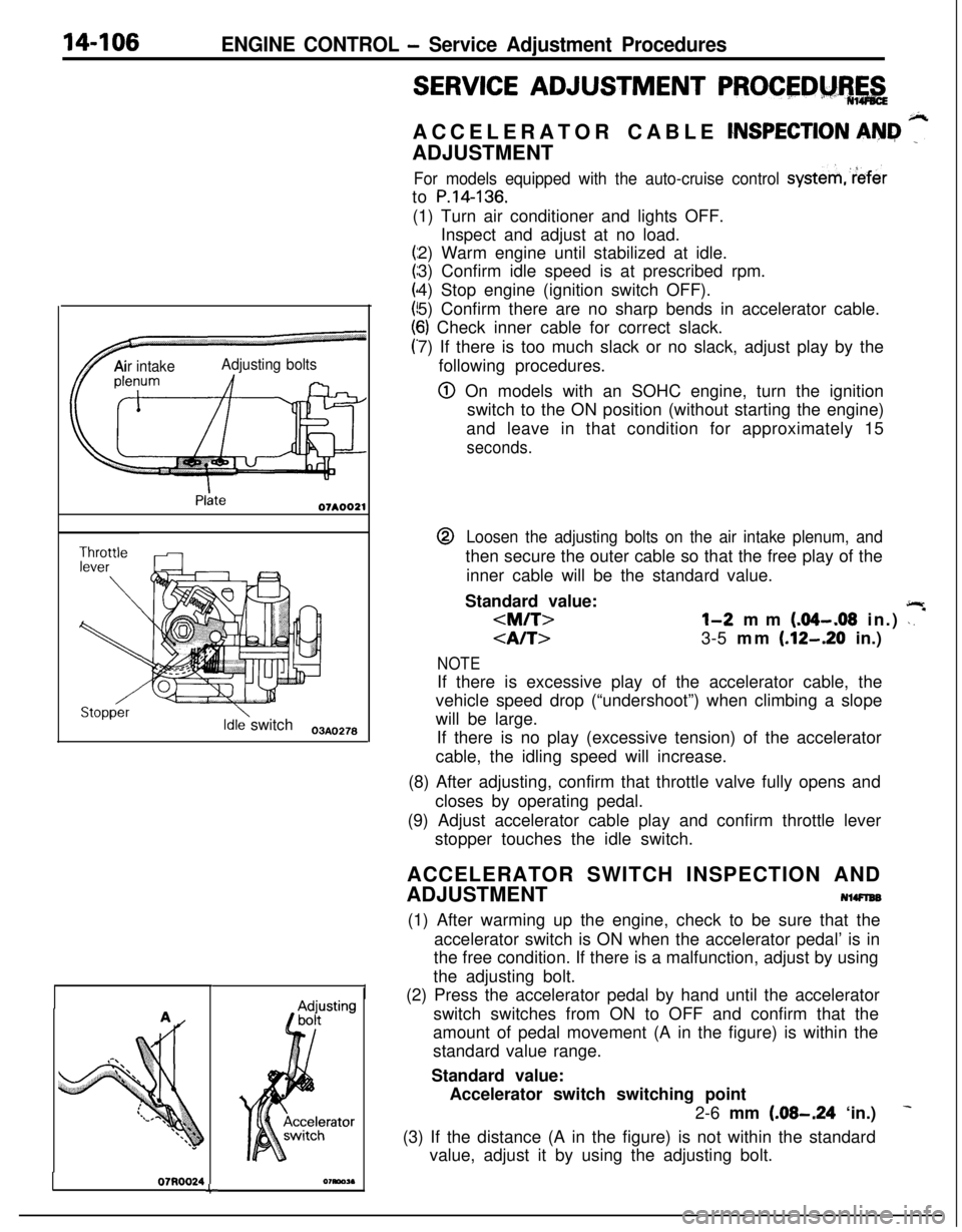
SERVICE ADJUSTMENT PROCEDM%,&ACCELERATOR CABLE
CNSPECTION AN&I ”ADJUSTMENT
For models equipped with the auto-cruise control systemreferto
P.14-136.(1) Turn air conditioner and lights OFF.
Inspect and adjust at no load.
2) Warm engine until stabilized at idle.
3) Confirm idle speed is at prescribed rpm.
4) Stop engine (ignition switch OFF).
5) Confirm there are no sharp bends in accelerator cable.
6) Check inner cable for correct slack.
7) If there is too much slack or no slack, adjust play by the
following procedures.
@ On models with an SOHC engine, turn the ignition
switch to the ON position (without starting the engine)
and leave in that condition for approximately 15
seconds.@
Loosen the adjusting bolts on the air intake plenum, andthen secure the outer cable so that the free play of the
inner cable will be the standard value.
Standard value:
jlr
3-5 mm (.12-.20 in.)
NOTEIf there is excessive play of the accelerator cable, the
vehicle speed drop (“undershoot”) when climbing a slope
will be large.
If there is no play (excessive tension) of the accelerator
cable, the idling speed will increase.
(8) After adjusting, confirm that throttle valve fully opens and
closes by operating pedal.
(9) Adjust accelerator cable play and confirm throttle lever
stopper touches the idle switch.
ACCELERATOR SWITCH INSPECTION AND
ADJUSTMENT
NlWlEB(1) After warming up the engine, check to be sure that the
accelerator switch is ON when the accelerator pedal’ is in
the free condition. If there is a malfunction, adjust by using
the adjusting bolt.
(2) Press the accelerator pedal by hand until the accelerator
switch switches from ON to OFF and confirm that the
amount of pedal movement (A in the figure) is within the
standard value range.
Standard value:
Accelerator switch switching point
2-6 mm
(.08-.24 ‘in.)
(3) If the distance (A in the figure) is not within the standard
value, adjust it by using the adjusting bolt.
Page 563 of 1216
AUTO-CRUISE CONTROL SYSTEM - Snecifications14-109
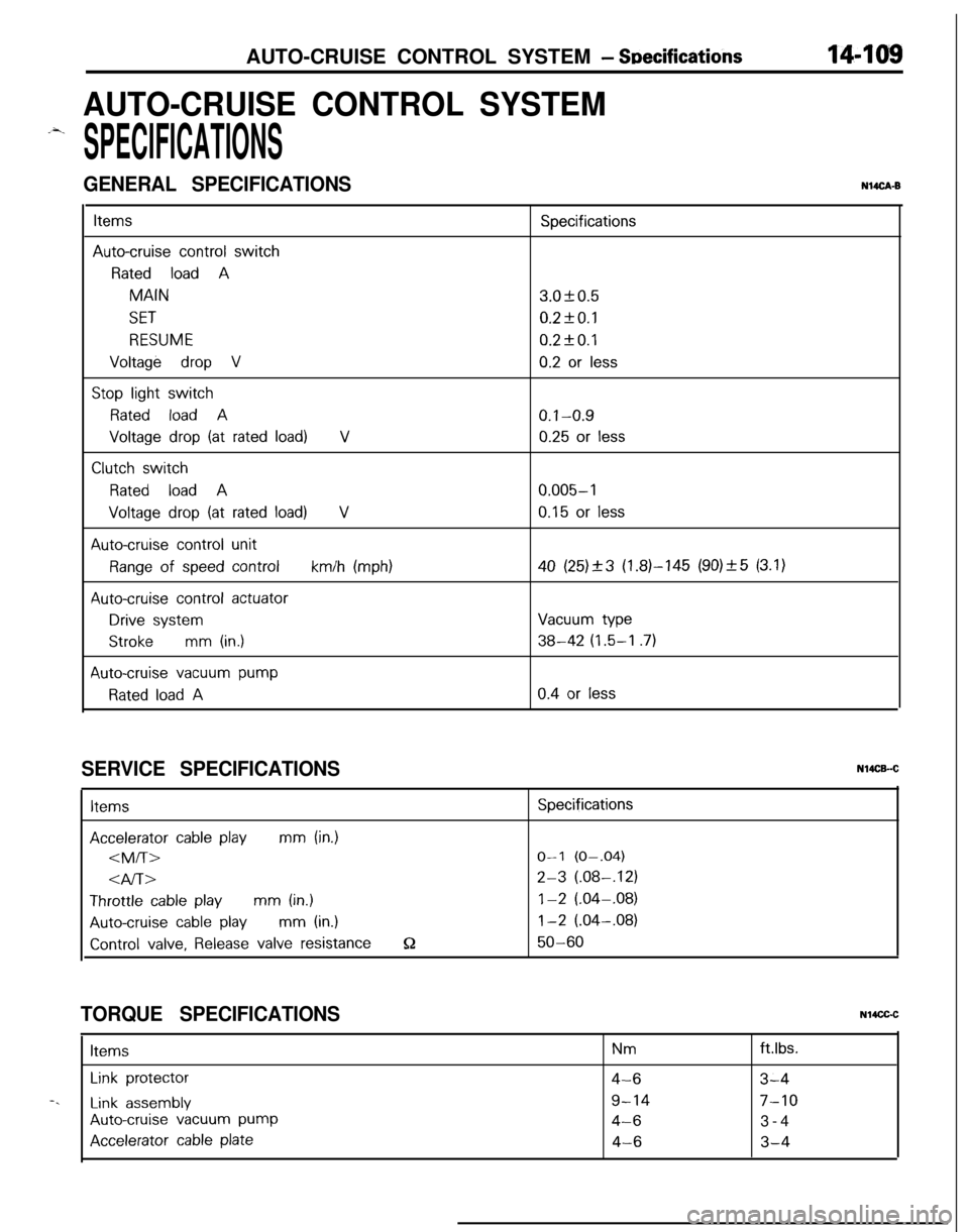
AUTO-CRUISE CONTROL SYSTEM
.-4.
SPECIFICATIONS
GENERAL SPECIFICATIONSNUCA-B
ItemsSpecifications
Auto-cruise control switch
Rated load AMAIN3.OkO.5
SET0.2fO.l
RESUME0.2kO.l
Voltage drop V0.2 or less
Stop light switch
Rated load A0.1-0.9
Voltage drop (at rated load)V0.25 or less
Clutch switch
Rated load A0.005-l
Voltage drop (at rated load)V0.15 or less
Auto-cruise control unit
Range of speed controlkm/h (mph)40 (25)_+3 (1.81-145 (90)_+5 (3.1)
Auto-cruise control actuator
Drive systemVacuum type
Strokemm (in.)38-42 (1.5-I .7)
Auto-cruise vacuum pump
Rated load A0.4 or less
SERVICE SPECIFICATIONSItems
Accelerator cable playmm (in.)
4l-bThrottle
cable playmm (in.)
Auto-cruise cable playmm (in.)
Control valve, Release valve resistanceQ
Specifications
O-l (O-.04)
2-3 (.08-,121
1-2 (.04-.08)
1-2 (.04-.08)
50-60
TORQUE SPECIFICATIONSN14CGCItems
Nmftlbs.
Link protector4-63-4-.
Link assembly9-147-10
Auto-cruise vacuum pump4-63-4
Accelerator cable plate4-63-4
Page 564 of 1216
AUTO-CRUISE CONTROL SYSTEM - Troubleshooting
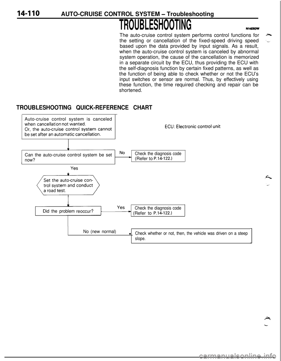
TROUBLESHOOTINGN14,EBPWThe auto-cruise control system performs control functions for
the setting or cancellation of the fixed-speed driving speed
based upon the data provided by input signals. As a result,
when the auto-cruise control system is canceled by abnormal
system operation, the cause of the cancellation is memorized
in a separate circuit by the ECU, thus providing the ECU with
the self-diagnosis function by certain fixed patterns, as well as
the function of being able to check whether or not the ECU’s
input switches or sensor are normal. Thus, by effectively usingthese function, the time required checking and repair can be
shortened.
TROUBLESHOOTING QUICK-REFERENCE CHARTAuto-cruise control system is canceled
when
cancellation not wanted.
Or, the auto-cruise control system cannot
be set after an automatic cancellation.
ECU: Electronic control unit
+-Can the auto-cruise control system be set
No cCheck the diagnosis code
now?(Refer to P.14-122.)II
Yes
Yes
Did the problem
reoccur?Check the diagnosis code
__c (Refer to P.14-122.)
No (new normal)lCheck whether or not, then, the vehicle was driven on a steep
slope.
Page 565 of 1216
AUTO-CRUISE CONTROL SYSTEM - Troubleshooting144w
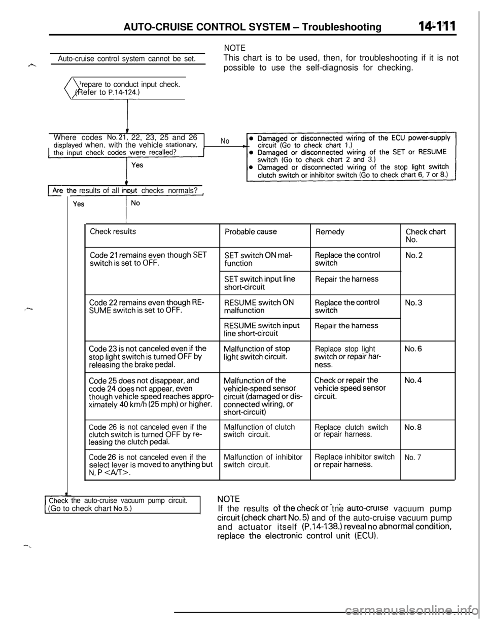
Auto-cruise control system cannot be set.
NOTEThis chart is to be used, then, for troubleshooting if it is not
possible to use the self-diagnosis for checking.
Prepare to conduct input check.
)( (Refer to P.14lrWhere codes
No.21, 22, 23, 25 and 26disolaved when, with the vehicle stationary,the’ input check codes were recalled?
‘#
No-8
cArc-3 ttie results of all inout checks normals?
L--y--
I
Check resultsProbable causeRemedy
ii”,:” chart
Code 21 remains even though SETSET switch ON mal-Replace the controlNo.2switch
is set to OFF.functionswitch
SET switch input lineRepair the harnessshort-circuit
:-Code 22 remains even though RE-SUME switch is set to OFF.RESUME switch ONmalfunction
RESUME switch input
line short-circuit
Replace the controlswitch
Repair the harnessNo.3
Code 23 is not canceled even if theMalfunction of stopReplace stop lightNo.6stop light switch
is turned OFF bylight switch circuit.switch or repair har-
releasing the brake pedal.ness.
Code 25 does not disappear, andMalfunction of theCheck or repair theNo.4
code 24 does not appear, evenvehicle-speed sensorvehicle speed sensor
though vehicle speed reaches appro-circuit (damaged or dis-circuit.ximately
40 km/h (25 mph) or higher.connected wiring, orshort-circuit)
Code 26 is not canceled even if theclutch switch is turned OFF by re-leasing the clutch pedal.Malfunction of clutch
switch circuit.
Replace clutch switchNo.8or repair harness.
Code 26 is not canceled even if theMalfunction of inhibitorReplace inhibitor switchNo. 7select lever is moved to anything butswitch circuit.or repair harness.
N, P
the auto-cruise vacuum pump circuit.NOTE_. . . e_,1 (Go to check chart No.5.)IIf the results of the check oT tne auro-crutse vacuum pump
circuit (check chart No. 5) and of the auto-cruise vacuum pump
and actuator itself (P.14-138.) reveal no abnormal
condition,replace
the electronic control unit (ECU).
-.
Page 566 of 1216

14-112AUTO-CRUISE CONTROL SYSTEM - Troubleshootina
Trouble symptomProbable causeCheck chart No.Remedy
l The set vehicle speed variesMalfunction of the vehi-No.4Repair the vehicle speec
greatly upward or downward.cle speed sensor circuitsensor system, or re-l “Hunching”
(repeated alternatingplace the part.
acceleration and deceleration)Malfunction of the
occurs after setting is made.speedometer cable orspeedometer drive gearAuto-cruise
vacuumNo.5Repair the auto-cruise
pump circuit poor con-vacuum pump, ortactreplace the part.Malfunction of the
auto-
cruise vacuum pumpMalfunction of the
ECU-Replace the ECU.
The auto-cruise control system is notDamaged or discon-If the input check codeRepair the harness or
canceled when the brake pedal isnetted wiring of theNo. 23 indicates a mal-replace the stop light
depressed.stop light switch inputfunction. No. 6switch.circuit; brake switch (forauto-cruise control) mal-function (short-circuit)Auto-cruise
vacuumNo. 5Repair the harness or
pump drive circuit short-replace the auto-cruisecircuitvacuum pump.Malfunction of the
ECU-Replace the ECU.
The auto-cruise control system is notDamaged or discon-If the input check codeRepair the harness, or
canceled when the clutch pedal isnetted wiring of clutchNo. 26 indicates a mal-repair or replace the
depressed. (vehicles with a manualswitch input circuitfunction. No. 8clutch switch.
transaxle)(It is canceled, however, when theClutch switch improper
brake pedal is depressed.)installation (won’tswitch ON)Malfunction of the
ECU-Replace the ECU.
The auto-cruise control system is notDamaged or discon-If the input check codeRepair the harness, orcanceled when the shift lever isnetted wiring of inhibi-No. 26 indicates a mal-repair or replace the in-
moved to the “N” position. (vehiclestor switch input circuitfunction. No.7hibitor switch.llvith an automatic transaxle)
[It is canceled, however, when theImproper adjustment of
Drake pedal is depressed.)inhibitor switchMalfunction of the
ECU-Replace the ECU.
Cannot decelerate by using the SETTemporary damaged orNo. 2Repair the harness orswitchdisconnected wiring ofreplace the SET switch.SET switch input circuitAuto-cruise
vacuumNo.5Repair the harness orpump circuit poor con-replace the auto-cruisetactvacuum pump andactuator.Malfunction of the auto-cruise vacuum pump
and actuator (includingclogging of negativepressure passage)Malfunction of the
ECU-Replace the ECU.
Page 567 of 1216
.z
c-AUTO-CRUISE CONTROL SYSTEM
- Tr6ubleshootina
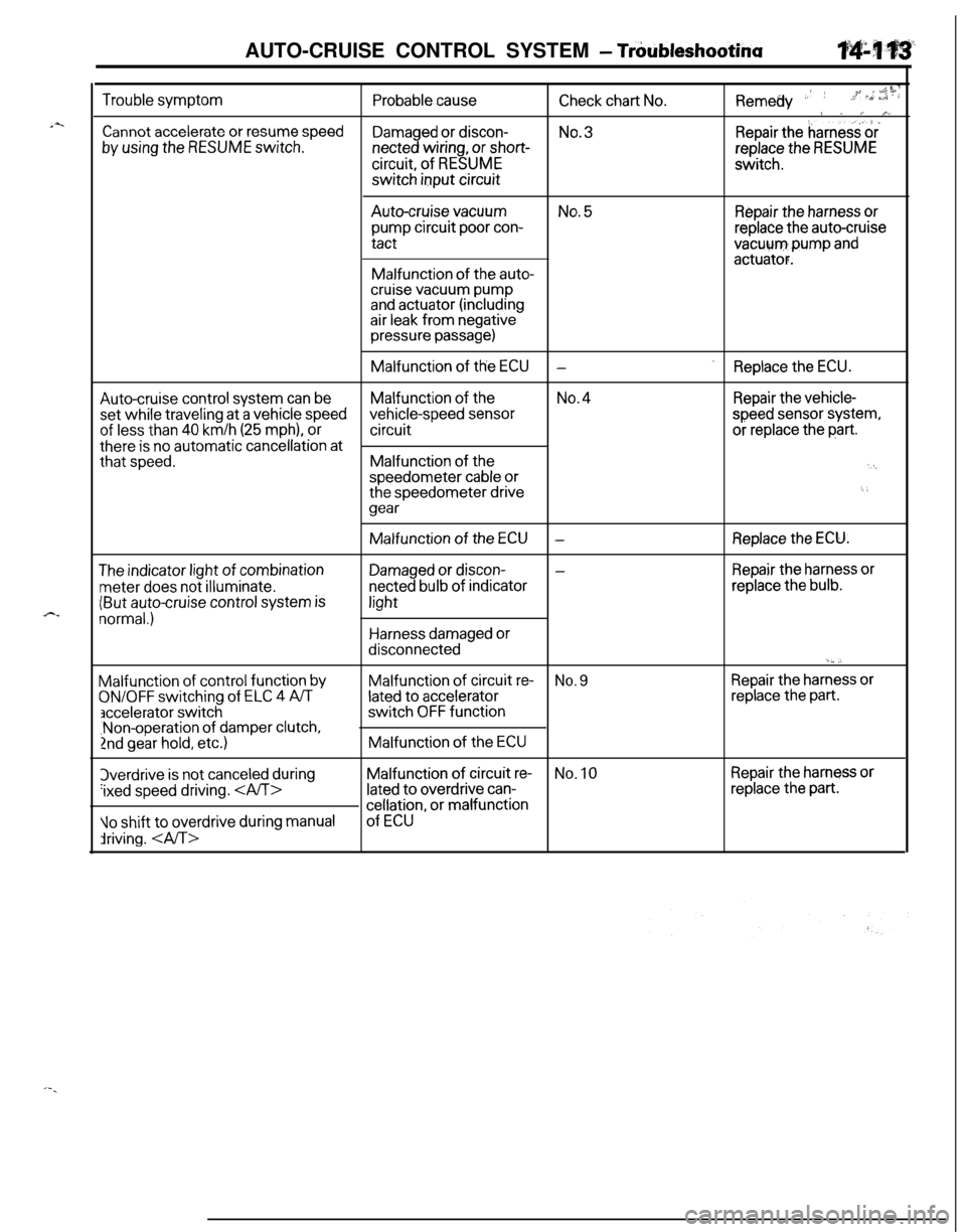
Trouble symptom
Cannot accelerate or resume speed
by using the RESUME switch.
Probable cause
Damaged or discon-netted wiring, or short-circuit, of
RESUMEswitch input circuit
Remedy .’ ’-c liiCheck chart No.,;+ >,, a”:; : :
9 . /~ A%No.3.Repair theharness‘&
replace the RESUMEswitch.Auto-cruise
vacuumNo. 5Repair the harness orpump circuit poor con-replace the auto-cruisetact
vacuum,pump andactuator.Malfunction of the auto-cruise vacuum pumpand actuator (includingair leak from negativepressure passage)Malfunction of the
ECU.-Replace the ECU.
Auto-cruise control system can beMalfunction of theNo.4Repair the vehicle-set while
traveling at a vehicle speedvehicle-speed sensorspeed sensor system,
of less than 40 km/h (25 mph), orcircuitor replace the part.there
is no automatic cancellation atthat
speed.Malfunction of the‘I,speedometer cable orthe speedometer drive6 i
gear
The indicator light of combination
meter does not illuminate.
(But auto-cruise control system is
normal.)Malfunction
of control function by
ON/OFF switching of ELC 4 A/T
accelerator switch,Non-operation of damper clutch,
2nd gear hold, etc.)3verdrive
is not canceled during
‘ixed speed driving.
10 shift to overdrive during manual
driving. Malfunction of the
ECU-Replace the ECU.
Damaged or discon--Repair the harness or
netted bulb of indicatorreplace the bulb.light
Harness damaged ordisconnected
‘._,.Malfunction of circuit
re-No. 9Repair the harness or
lated to acceleratorreplace the part.switch
OFF functionMalfunction of the
ECUMalfunction of circuit
re-No. 10Repair the harness or
lated to overdrive can-replace the part.
cellation, or malfunction
of ECU
Page 568 of 1216
14-114AUTO-CRUISE CONTROL SYSTEM - Troubleshooting
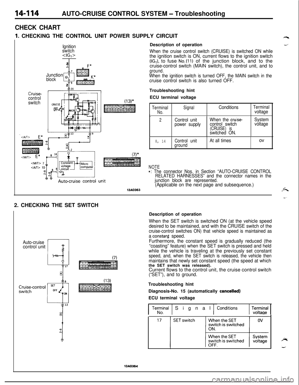
CHECK CHART
1I. CHECKING THE CONTROL UNIT POWER SUPPLY CIRCUIT
Ignition
switch
IAF”7Junction 8
block
tI3
Crurse-controlswitch
OFFDescription of operation
When the cruise control switch (CRUISE) is switched ON whilethe ignition switch is ON, current flows to the ignition switch(IG,), to fuse No.(ll) of the junction block, and to thecruise-control switch (MAIN switch), the control unit, and to
ground.When the ignition switch is turned OFF, the MAIN switch in thecruise control switch is also turned OFF.Troubleshooting hint
ECU terminal voltage
TerminalSignal
No.ConditionsTerminalvoltage
t2Control unitWhen the cruise-System
power supplycontrol switchvoltage
(CRUISE) isswitched ON.
8, 14Control unitAt all timesovground
NOTE+: The connector Nos. in Section “AUTO-CRUISE CONTROL
RELATED HARNESSES” and the connector names in the
junction block are represented.
(Applicable on the next page and subsequence.)13AO3632. CHECKING THE SET SWITCH
Auto-cruisecontrol unitDescription of operation
When the SET switch is switched ON (at the vehicle speed
desired to be maintained, and with the CRUISE switch of the
cruise-control switches ON) that vehicle speed is maintained as
a constanf speed.
Furthermore, the constant speed is gradually reduced (the
“coasting” feature) when the SET switch is pressed and held
while the vehicle is traveling at the previously set constant
speed, and, when the SET switch is released, the vehicle then
maintains that newly set constant speed (the speed at whichthe SET switch was released).
Current flows to the control unit, the cruise control switch
(“SET”), and to ground.Troubleshooting hint
Diagnosis-No. 15 (automatically
cancelled)ECU terminal voltage
1 Terrrnal 1 Signal 1 ConditionsrEl
13AO364
Page 569 of 1216
AUTO-CRUISE CONTROL SYSTEM - Troubleshooting
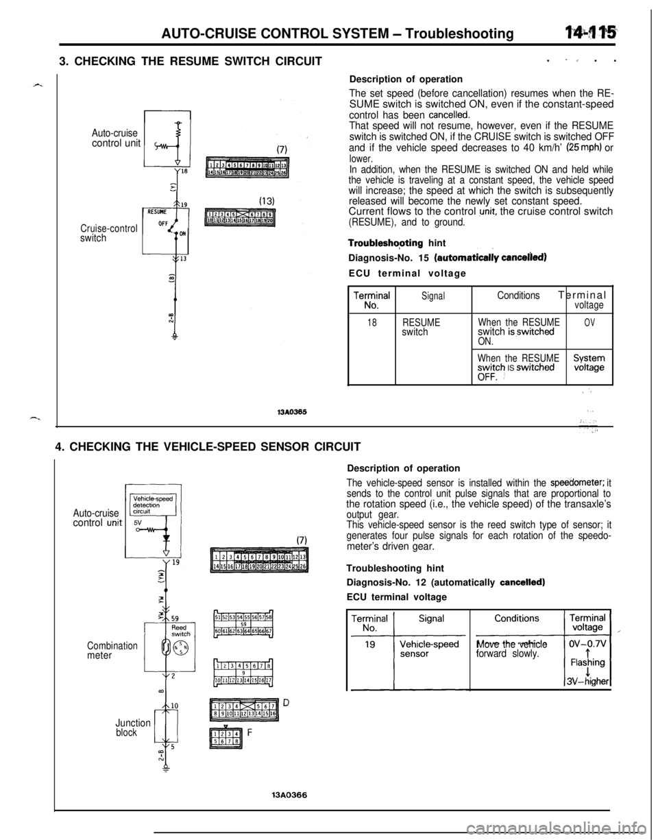
3. CHECKING THE RESUME SWITCH CIRCUIT.
” ,, . .
Auto-cruisecontrol unit
Cruise-controlswitchDescription of operation
The set speed (before cancellation) resumes when the RE-SUME switch is switched ON, even if the constant-speed
control has been cancelled.That speed will not resume, however, even if the RESUME
switch is switched ON, if the CRUISE switch is switched OFF
and if the vehicle speed decreases to 40 km/h’
(25 mph) or
lower.
In addition, when the RESUME is switched ON and held while
the vehicle is traveling at a constant speed, the vehicle speed
will increase; the speed at which the switch is subsequently
released will become the newly set constant speed.Current flows to the control
unit, the cruise control switch
(RESUME), and to ground.
Troubleshopting hint
Diagnosis-No. 15
(automatica& canceelied)ECU terminal voltage
Tez3!alSignalConditionsTerminalvoltage
18RESUMEWhen the RESUMEOVswitchswitch is,switchedON.
When the RESUME
“o”;:“h IS swrtched;;;;g;
\ ‘)
13AO365,,4. CHECKING THE VEHICLE-SPEED SENSOR CIRCUIT
Auto-cruisecontrol unit
Combination
meter
Junction
block
13A0366Description of operation
The vehicle-speed sensor is installed within the sljeedometer; it
sends to the control unit pulse signals that are proportional to
the rotation speed (i.e., the vehicle speed) of the transaxle’soutput gear.
This vehicle-speed sensor is the reed switch type of sensor; it
generates four pulse signals for each rotation of the speedo-
meter’s driven gear.Troubleshooting hint
Diagnosis-No. 12 (automatically
cancelled)ECU terminal voltage
Move the vehicle
forward slowly.
Page 570 of 1216
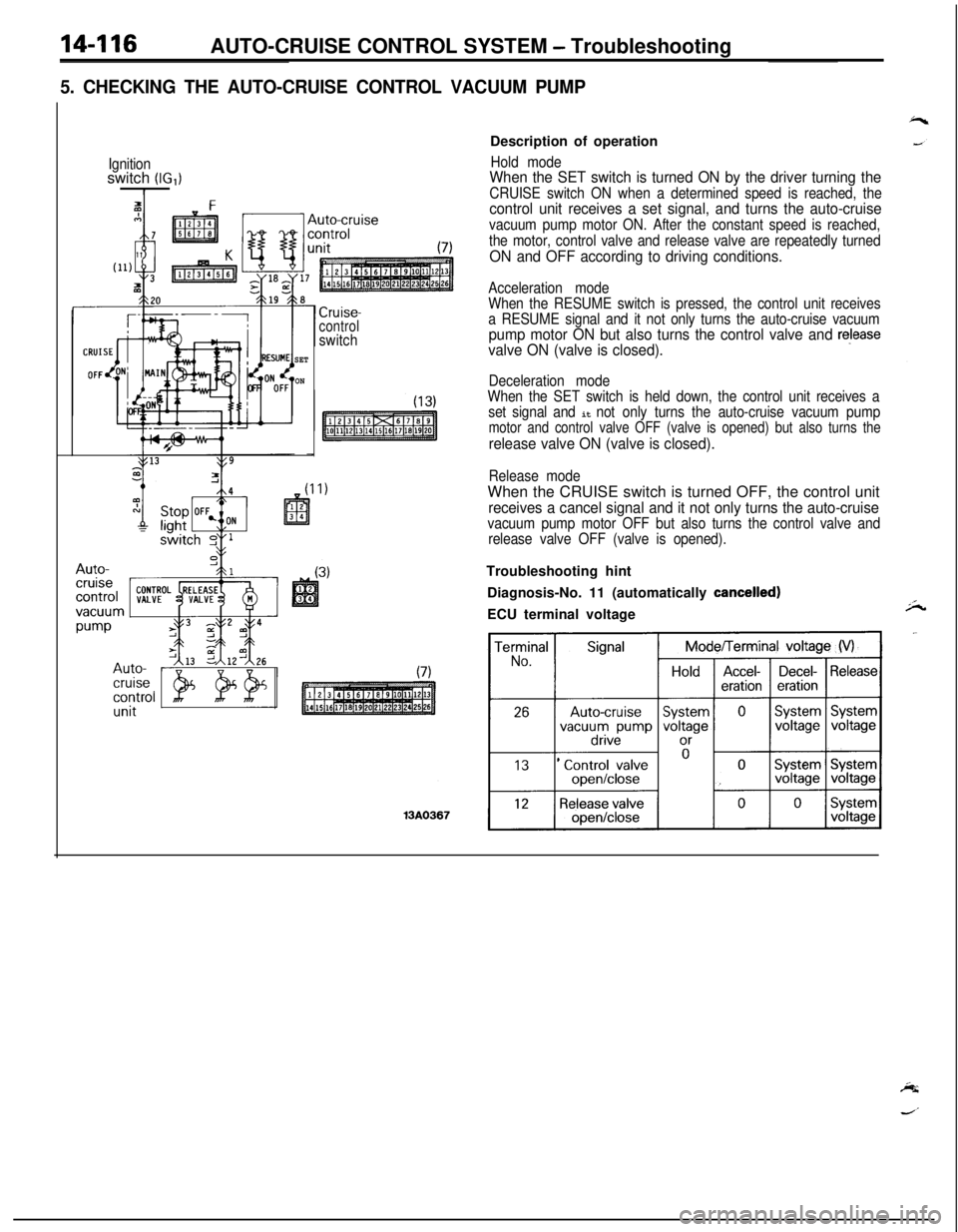
14-116AUTO-CRUISE CONTROL SYSTEM - Troubleshooting
5. CHECKING THE AUTO-CRUISE CONTROL VACUUM PUMP
Ignitionswitch (IG,)I
SET
ON
Cruise-controlswitchDescription of operation
Hold modeWhen the SET switch is turned ON by the driver turning the
CRUISE switch ON when a determined speed is reached, thecontrol unit receives a set signal, and turns the auto-cruise
vacuum pump motor ON. After the constant speed is reached,
the motor, control valve and release valve are repeatedly turned
ON and OFF according to driving conditions.
Acceleration mode
When the RESUME switch is pressed, the control unit receives
a RESUME signal and it not only turns the auto-cruise vacuum
pump motor ON but also turns the control valve and releasevalve ON (valve is closed).
Deceleration mode
When the SET switch is held down, the control unit receives a
set signal and
it not only turns the auto-cruise vacuum pumpmotor and control valve OFF (valve is opened) but also turns the
release valve ON (valve is closed).
Release modeWhen the CRUISE switch is turned OFF, the control unit
receives a cancel signal and it not only turns the auto-cruisevacuum pump motor OFF but also turns the control valve and
release valve OFF (valve is opened).Troubleshooting hint
Diagnosis-No. 11 (automatically
cancelled)ECU terminal voltage