gas type MITSUBISHI ECLIPSE 1991 User Guide
[x] Cancel search | Manufacturer: MITSUBISHI, Model Year: 1991, Model line: ECLIPSE, Model: MITSUBISHI ECLIPSE 1991Pages: 1216, PDF Size: 67.42 MB
Page 1090 of 1216
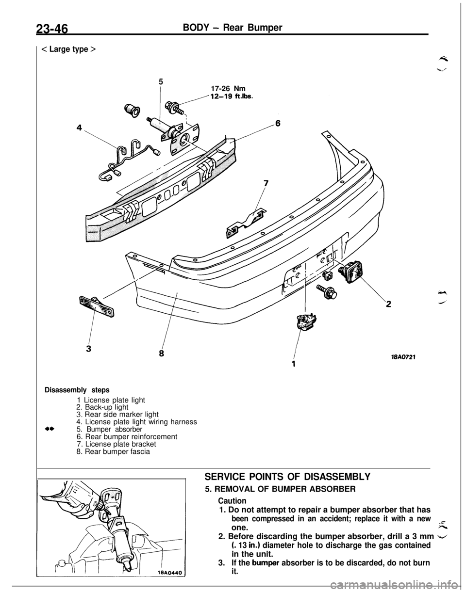
23-46BODY - Rear Bumper
< Large type >
517-26 Nm
18A0721
Disassembly steps1 License plate light
2. Back-up light
3. Rear side marker light
4. License plate light wiring harness
4*5. Bumper absorber6. Rear bumper reinforcement
7. License plate bracket
8. Rear bumper fascia
SERVICE POINTS OF DISASSEMBLY5. REMOVAL OF BUMPER ABSORBER
Caution1. Do not attempt to repair a bumper absorber that has
been compressed in an accident; replace it with a new-one.
-F--2. Before discarding the bumper absorber, drill a 3 mm
-z
(. 13 in.1 diameter hole to discharge the gas containedin the unit.
3.
If the bumper absorber is to be discarded, do not burn
it.
Page 1154 of 1216
24-10HEATERS AND AIR CONDITIONING - Safety Precautions
SAFETY PRECAUTIONSN24PAAD
The refrigerant used in all air conditioner is R-l 2. It istransparent and colorless in both the liquid and
vapor state. Since it has a boiling point of
-29.8”C(-85.6”F).
at atmospheric pressure, it will be a vapor
at all normal temperatures and pressures. The vaporis heavier than air, non-flammable, and nonexplo-
sive. It is nonpoisonous except when it is in direct
contact with open flame. It
ia noncorrosive except
when combined with water. The following precau-
tions must be observed when handling
R-12.Caution
Wear safety goggles when servicing the refriger-ation system.
R-12 evaporates so rapidly at normal atmospheric
pressures and temperatures that it tends to freeze
anything it contacts. For this reason, extreme care
must be taken to prevent any liquid refrigerant from
contacting the skin and especially the eyes. Always
wear safety goggles when servicing the refrigera-
tion part of the air conditioning system. Keep a
bottle of sterile mineral oil handy when working on
the refrigeration system. Should any liquid re-
frigerant get into the eyes, use a few drops of
mineral oil to wash them out.
R-12 is rapidly
absorbed by the oil. Next splash the eyes with
plenty of cold water. Call your doctor immediately
even though irritation has ceased after treatment.
Caution
Do not heat
R-12 above 40°C (104°F).In most instances, moderate heat is required to
bring the pressure of the refrigerant in its container
above the pressure of the system when charging or
adding refrigerant. A bucket or large pan of hot
water not over
40°C (104°F) is all the heat required
for this purpose. Do not heat the refrigerant contain-
er with a blow torch or any other means that would
raise temperature and pressure above this tempera-ture. Do not weld or steam clean on or near the
system components or refrigerant lines.
Caution
Keep
R-12 containers upright when charging the
system.When metering
R-12 into the refrigeration system,
keep the supply tank or cans in an upright position. Ifthe refrigerant container is on its side or upside
down, liquid refrigerant will enter the system and
damage the compressor.Caution
Always work in a well-ventilated room.
‘irrGood ventilation is vital in the working area. Always
discharge the refrigerant into the service bay ex-
haust system or outside the building. Large quanti-
ties of refrigerant vapor in a small, poorly ventilated
room can displace the air and cause suffocation.
Although
R-12 vapor is normally nonpoisonous,
contact with an open flame can cause the vapor to
become very poisonous. Do not discharge large
quantities of refrigerant in an area having an open
flame. A poisonous gas is produced when using theflame-type leak detector. Avoid inhaling the fumes
from the leak detector.
Caution
Do not allow liquid refrigerant to touch bright
metal.
Refrigerant will tarnish bright metal and chrome
surfaces, and in combination with moisture can
severely corrode all metal surfaces.
R-12 Refrigerant Bundling
Refrigerant Recycling
R-12 refrigerant is a chloro-floro-carbon (CFC) that
can contribute to the depletion of the ozone layer in
the upper atmosphere.A
Ozone filters out harmful radiation from the sun.
- -/.To assist in protecting the ozone layer, Mitsubishi
Motors Corporation
recomends that a R-12 re-
frigerant recycling device that meets SAE standard
J1991 be used.
Contact an automotive service equipment supplier
for refrigerant recycling equipment that is available
in your area.
Refer to the operating instructions provided with therecycling equipment for proper operation.
Page 1165 of 1216
i
HEATERS AND AIR CONDITIONING - Service Adjustment Procedures 24-21Hot water40°C (104°F)
1467CHARGING SYSTEM
The refrigerant system must have been evacuated using the
previous procedure before charging.
Charge using only R-l 2 refrigerant.
R-12 is available in bulk
tanks or small cans. Follow the safety precautions for handling
R-12 as listed in this group.
Charging with Small Cans
When using disposable cans of this type, follow carefully the
can manufacturers instructions.
Caution
Never use these cans to charge into the high pressure side
of the system (compressor discharge port) or into a systemthat is at high temperature, because the high system
pressures could be transferred into the charging can
causing it to explode.
Keep the refrigerant manifold valves capped when not in use.
Keep a supply of extra refrigerant-can-to-refrigerant-manifold
gaskets on hand so that gaskets can be replaced periodically.
This will insure a good seal without excessive tightening of thecan or the manifold nuts.
(1) Attach center hose from manifold gauge set to refrigerant
dispensing manifold. Turn refrigerant manifold valves com-pletely anticlockwise so they are fully open.
Remove protective caps from refrigerant manifold.
(2) Screw refrigerant cans into manifold. Be sure
manifold-to-can gasket is in place and in good condition. Tighten can
and manifold nuts to 8 to 11 Nm (6 to 8
ft.lbs.).(3) Turn refrigerant manifold valves completely clockwise to
puncture the cans and close the manifold valves.
(4) Purge the air from the charging line by loosening the
charging hose at the gauge set manifold and turning one ofthe refrigerant valves anticlockwise to release refrigerant.
When the refrigerant gas starts escaping from the loose
connection, re-tighten the hose.
Caution
Never heat small refrigerant cans over
40°C (104°F) as
they may explode.
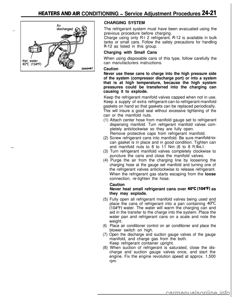
(5) Fully open all refrigerant manifold valves being used and
place the cans of refrigerant into a pan containing
40°C
(104°F) water. The water will warm the charging can and
aid in the transfer to the charge into the system. Place the
water pan and refrigerant cans on a scale and note the
weight.
(6)Place air conditioner control on air conditioner and place theblower switch on high.
(7) Open the discharge and suction gauge valves of the gaugemanifold, and charge gas from the both.
Keep refrigerant container upright.
(8) When suction of refrigerant is saturated, close the dis-
charge and suction gauge valves once, and start the
engine. Fix the engine revolution speed at approx. 1,500
rpm.
Page 1195 of 1216
HEATERS AND AIR CONDITIONING- Engine Coolant Temperature Switch24-51
ENGINE COOLANT TEMPERATURE SWITCH <2.0L DOHC Engine>
-.REMOVAL AND INSTALLATIONN24xA-
1 to GROUP f-service Adjust-1ment Procedures.)
22-28
ft.lbs.
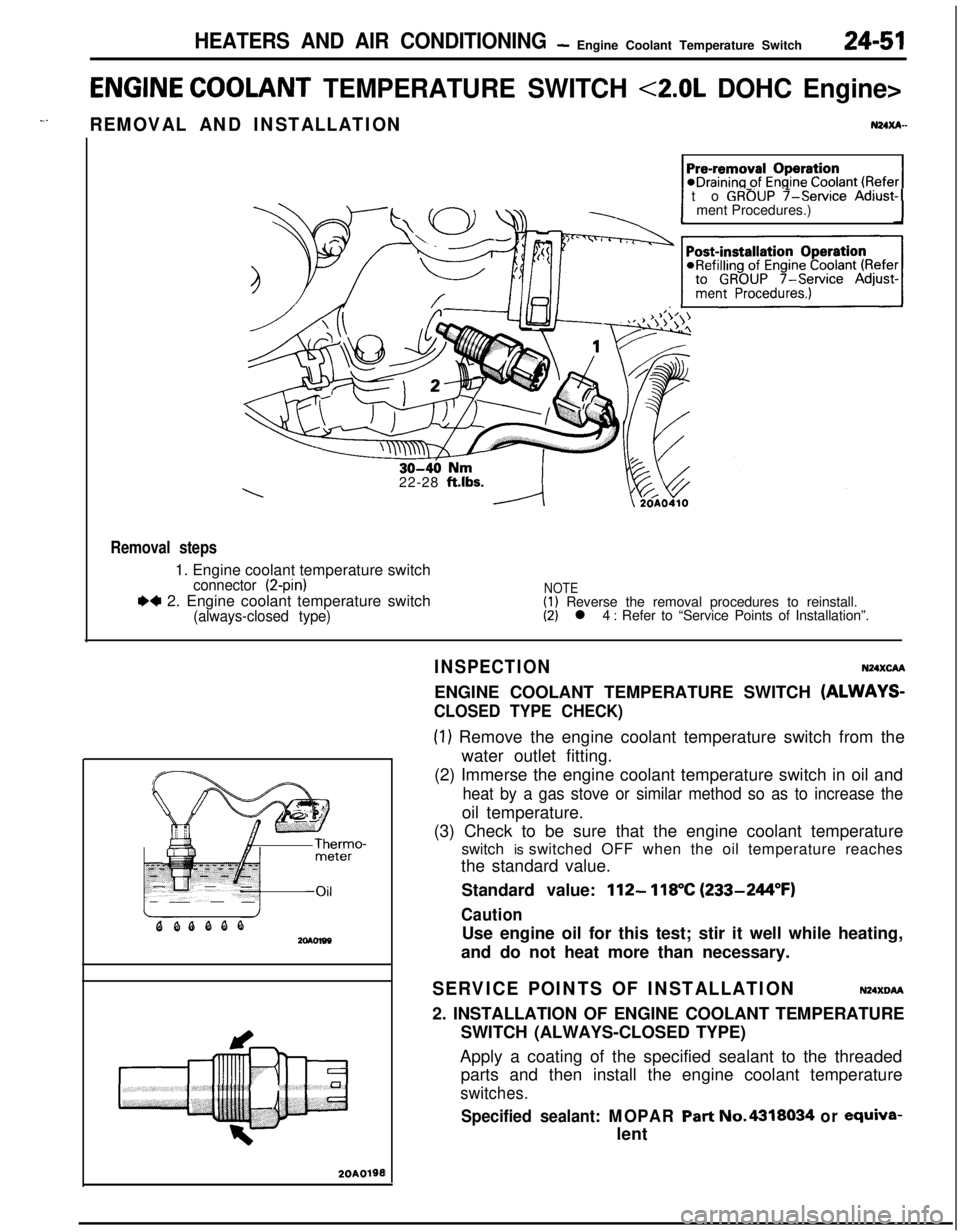
Removal steps1. Engine coolant temperature switch
connector (2-pin)
.4 2. Engine coolant temperature switch(always-closed type)
NOTE(1) Reverse the removal procedures to reinstall.(2) l 4 : Refer to “Service Points of Installation”.
20A0190I
INSPECTIONN24XcAAENGINE COOLANT TEMPERATURE SWITCH
(ALWAYS-
CLOSED TYPE CHECK)
(1) Remove the engine coolant temperature switch from the
water outlet fitting.
(2) Immerse the engine coolant temperature switch in oil and
heat by a gas stove or similar method so as to increase theoil temperature.
(3) Check to be sure that the engine coolant temperature
switch is switched OFF when the oil temperature reaches
the standard value.
Standard value:
112- 118°C (233-244°F)
CautionUse engine oil for this test; stir it well while heating,
and do not heat more than necessary.
SERVICE POINTS OF INSTALLATIONN24XDM2. INSTALLATION OF ENGINE COOLANT TEMPERATURE
SWITCH (ALWAYS-CLOSED TYPE)
Apply a coating of the specified sealant to the threaded
parts and then install the engine coolant temperature
switches.
Specified sealant: MOPAR Part No.4318034 or ewiva-lent
Page 1198 of 1216

EMISSION CONTROL SYSTEMS - Specifications
SPECIFICATIONS
GENERAL SPECIFICATIONSN25CA-ItemsSpecifications
.,:..rCrankcase emission control systemClosed type with positive crankcase ventilation valve”I
‘:Evaporative emission control systemCanister storage type
CanisterCharcoal type
Exhaust emission control system
Exhaust gas recirculation system
EGR valveVacuum-activated diaphragm type
Therm0 valveBimetal type
EGR temperature sensor
EGR control solenoid valve
Duty cycle solenoid valve
Catalytic converterMonolith type
LocationUnder floor
SERVICE SPECIFICATIONSN25CB-
ItemsSpecifications
Purge-control solenoid valve coil resistance
&236-44 [at 20°C (68”F)I
Therm0 valve closing temperature“C (“F)65 (149)
EGR temperature sensor resistance
kQ60-83 [at 50°C (122”F)]11-14 [at
100°C (212”F)]EGR control solenoid valve coil resistance
S236-44 [at 20°C (68”F)]
TORQUE SPECIFICATIONSN25CC-
ItemsPositive crankcase ventilation valve
EGR valve installation bolt
<2.0L DOHC Engine>
Therm0 valve
EGR temperature sensor
Nmftlbs.8-12
6-8.5
IO-157.2-1015-22
10-15.5
20-4015-30
10-127.3-8.6
SEALANT
Items
Therm0 valve thread portionSpecified sealant
MOPAR Part No.4318034 or equivalent
Page 1216 of 1216
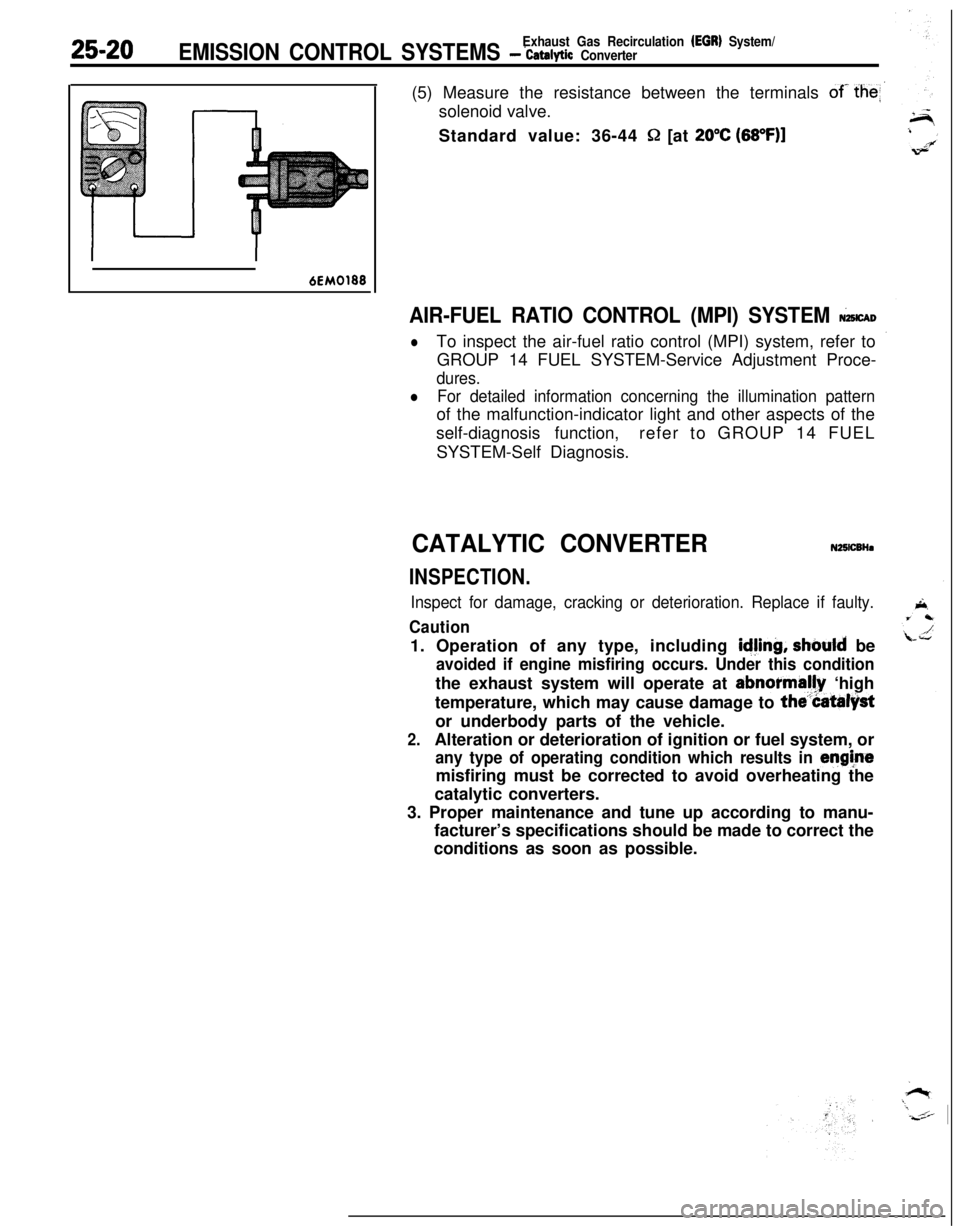
25-20Exhaust Gas Recirculation (EGR) System/EMISSION CONTROL SYSTEMS - ‘catalytic Converter(5) Measure the resistance between the terminals
of- the
Q [at 20°C (68OF)l
6EM0188
AIR-FUEL RATIO CONTROL (MPI) SYSTEM &CAD
lTo inspect the air-fuel ratio control (MPI) system, refer to
GROUP 14 FUEL SYSTEM-Service Adjustment Proce-
dures.
lFor detailed information concerning the illumination patternof the malfunction-indicator light and other aspects of the
self-diagnosis function,refer to GROUP 14 FUEL
SYSTEM-Self Diagnosis.
CATALYTIC CONVERTERN25lCBHa
INSPECTION.
Inspect for damage, cracking or deterioration. Replace if faulty.
Caution1. Operation of any type, including
idjing, should be
avoided if engine misfiring occurs. Under this conditionthe exhaust system will operate at abnormally ‘high
temperature, which may cause damage to
the”Catalystor underbody parts of the vehicle.
2.Alteration or deterioration of ignition or fuel system, or
any type of operating condition which results in enghtemisfiring must be corrected to avoid overheating the
catalytic converters.
3. Proper maintenance and tune up according to manu-
facturer’s specifications should be made to correct the
conditions as soon as possible.