gas type MITSUBISHI ECLIPSE 1991 Service Manual
[x] Cancel search | Manufacturer: MITSUBISHI, Model Year: 1991, Model line: ECLIPSE, Model: MITSUBISHI ECLIPSE 1991Pages: 1216, PDF Size: 67.42 MB
Page 36 of 1216
o-2LUBRICATION AND MAINTENANCE - General Information
GENERAL INFORMATIONNGQPA--Maintenance and lubrication service recommenda-
tions have been compiled to provide maximum
protection for the vehicle owner’s investment
against all reasonable types of driving conditions.
Since these conditions vary with the individual
vehicle owner’s driving habits, the area in which the
vehicle is operated and the type of driving to which
the vehicle is subjected, it is necessary to prescribe
lubrication and maintenance service on a time
frequency as well as mileage interval basis.
Oils, lubricants and greases are classified and
graded according to standards recommended by theSociety of Automotive Engineers (SAE), the Amer-
ican Petroleum Institute (API) and the National
Lubricating Grease Institute
(NLGI).MAINTENANCE SCHEDULES
Information for service maintenance is provided
under “SCHEDULED MAINTENANCE TABLE”.
Three schedules are provided; one for “Required
Maintenance”, one for “General Maintenance” and
one for “Severe Usage Service”.
Item numbers in the “SCHEDULED MAINTE-
NANCE TABLE” correspond to the item numbers in
the “MAINTENANCE SERVICE” section.
SEVERE SERVICEVehicles operating under severe service conditions
will require more frequent service.
Component service information is included in
appropriate units for vehicles operating under one ormore of the following conditions:
1.Trailer towing or police, taxi, or commercial type
operation2. Operation of Vehicle
(1) Short-trip operation at freezing temperature
(engine not thoroughly warmed up)
(2) More than 50% operation in heavy city
traffic during hot weather above
32°C (90°F)(3) Extensive idling
(4) Driving in sandy areas
(5) Driving in salty areas
(6) Driving in dusty conditions
ENGINE OIL
The SAE grade number indicates the viscosity of
engine oils, for example, SAE 30, which is a single
grade oil. Engine oils are also identified by a dual
number, for example, SAE
lOW-30, which indicates
a multigrade oil.
The API classification system defines oil perform-
ance in terms of engine usage. Only engine oil
designed “For Service SG” or “For Service
SGKD”,when available, should be used. These oils contain
sufficient chemical additives to provide maximum
engine protection. Both the SAE grade and the API
designation can be found on the container.Caution
Test results submitted to EPA have shown thatlaboratory animals develop skin cancer after
prolonged contact with used engine oil. Accor-
dingly, the potential exists for humans
to de-
velop a number of skin disorders, including
cancer, from such exposure to used engine oil.
Care should be’ taken, therefore, when changingengine oil, to minimize the amount and length of
exposure time to used engine
pi! on your skin.
Protective clothing and gloves, that cannot be
penetrated by oil, should be worn. The skin
should be thoroughly washed with soap and
water, or use waterless hand cleaner, to removeany used engine oil. Do not use gasoline,
thinners, or solvents.
GEAR LUBRICANTSThe SAE grade number also indicates the viscosity
of Multi-Purpose Gear Lubricants.
The API classfication system defines gear lubricants
in terms of usage. Typically gear lubricants conform-ing to API
GL-4 or GL-5 with a viscosity of SAE
75W-85W are recommended for manual transaxle.
LUBRICANTS
- GREASES
Semi-solid lubricants, bear the NLGI designation andare further classified as grades 0, 1, 2, 3 etc.
Whenever “Chassis Lubricant” is specified, Multi-
Purpose Grease,
NLGI grade 2 should be used.
MOPAR Multi-Mileage Lubricant, P&t Number
2525035 or equivalent, meets these requirement
and is recommended.
FUEL USAGE STATEMENT
Use gasolines having a minimum anti-knock index
(Octane Value) of 87,
(R + M)/2. This designation is
comparable to a Research Octane Number of 91.
Unleaded gasolines only must be used in vehicles
equipped with catalyst emission control systems.
All vehicles, so equipped, have labels located on the
instrument panel and on the back of fuel filler lid that
state, “UNLEADED GASOLINE ONLY”. These vehi-
cles also have fuel filler tubes especially designed toaccept the smaller diameter unleaded gasoline
dispensing nozzles only.
MATERIALS ADDED
TO FUELIndiscriminate use of fuel system cleanng agents
should be avoided. Many of these materials in-
tended for gum and varnish removal may contain
highly active solvents or similar ingredients that can
be harmful to gasket and diaphragm materials usedin fuel system component parts.
Page 86 of 1216
2-38FRONT SUSPENSION - Stabilizer Bar
40-60 Nm
29-43 fLlb52-72
klbs.
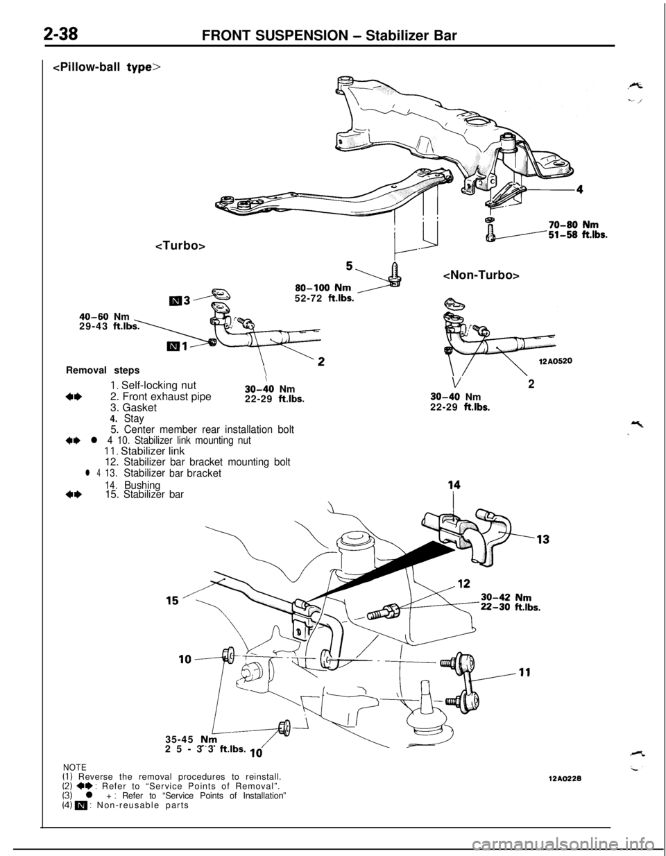
Removal steps
4*
1, Self-locking nut
2. Front exhaust pipe
3. Gasket30-:O Nm
22-29 ftlbs.
V2
30-40 Nm
22-29 ft.lbs.
4.Stay
5. Center member rear installation bolt
4e l 4 10. Stabilizer link mounting nutII. Stabilizer link12. Stabilizer bar bracket mounting bolt
l 413.Stabilizerbarbracket
14.Bushing4*15. Stabilizer bar
c- r35-45
25-33
ft.lbs. 10
NOTE(I) Reverse the removal procedures to reinstall.(2) 4e : Refer to “Service Points of Removal”.(3) l + : Refer to “Service Points of Installation”(4) m : Non-reusable parts12A0228
Page 292 of 1216
9-8ENGINE - Specifications
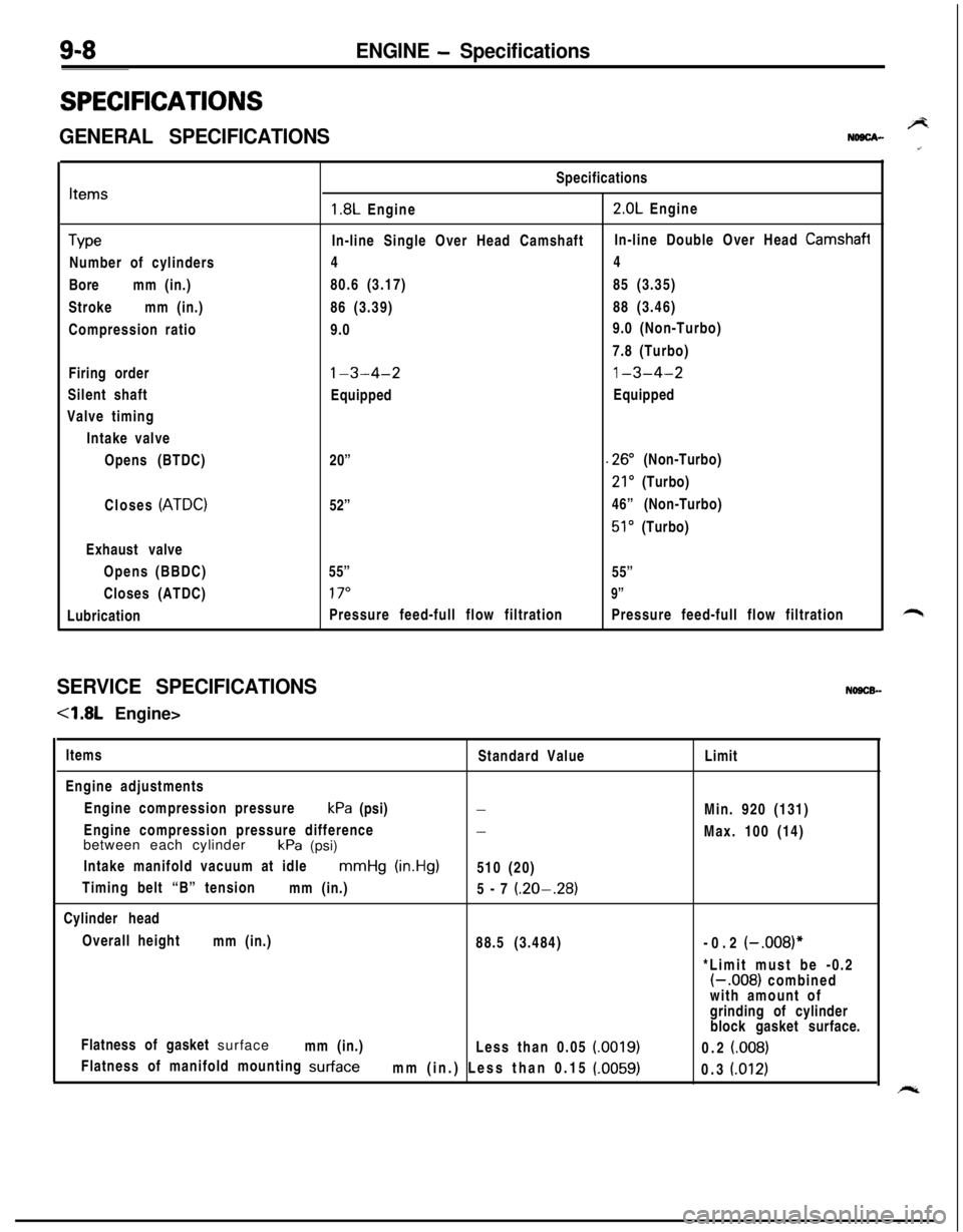
SPECIFICATIONS
GENERAL SPECIFICATIONSBNDBCA-
Items
TypeNumber of cylinders
Boremm (in.)
Strokemm (in.)
Compression ratio
Firing order
Silent shaft
Valve timing
Intake valve
Opens (BTDC)
Closes
(ATDC)Exhaust valve
Opens (BBDC)
Closes (ATDC)
LubricationSpecifications
1.8L Engine2.0L Engine
In-line Single Over Head CamshaftIn-line Double Over Head
Camshafi44
80.6 (3.17)85 (3.35)
86 (3.39)88 (3.46)
9.09.0 (Non-Turbo)
7.8 (Turbo)
l-3-4-21-3-4-2EquippedEquipped
20”
.26” (Non-Turbo)
21’ (Turbo)
52”46” (Non-Turbo)
51’ (Turbo)
55”
55”
17”9”Pressure feed-full flow filtrationPressure feed-full flow filtration
SERVICE SPECIFICATIONSNOSCB-
-4.8L Engine>
Items
Standard Value
Engine adjustments
Engine compression pressurekPa (psi)
-Engine compression pressure difference
-between each cylinder
kPa (psi)
Intake manifold vacuum at idle
mmHg (in.Hg)510 (20)
Timing belt “B” tension
mm (in.)
5-7
(.20-.28)Cylinder head
Overall height
mm (in.)
88.5 (3.484)
Flatness of gasket surface
mm (in.)
Less than 0.05
(0019)Flatness of manifold mounting
surfacemm (in.) Less than 0.15 (.0059)Limit
Min. 920 (131)
Max. 100 (14)
-0.2
(-.008)**Limit must be -0.2
(-.008) combined
with amount of
grinding of cylinder
block gasket surface.
0.2
(008)0.3
(.012)
Page 424 of 1216
11-2INTAKE AND EXHAUST - Specifications
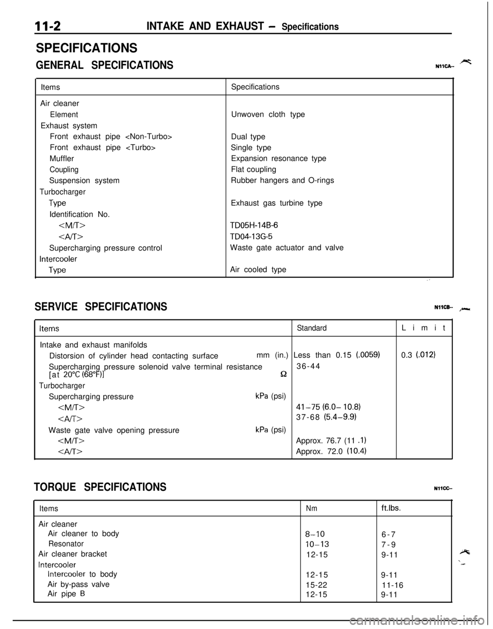
SPECIFICATIONS
GENERAL SPECIFICATIONS.prtNIICA-Items
Air cleaner
ElementExhaust system
Front exhaust pipe
Front exhaust pipe
Muffler
CouplingSuspension system
Turbocharger
TypeIdentification No.
4iT>Supercharging pressure control
Intercooler
TypeSpecifications
Unwoven cloth type
Dual type
Single type
Expansion resonance type
Flat coupling
Rubber hangers and O-rings
Exhaust gas turbine type
TD05H-14B-6
TD04-13G-5Waste gate actuator and valve
Air cooled type
SERVICE SPECIFICATIONSNllCB- spr*
ItemsStandardIntake and exhaust manifolds
Distorsion of cylinder head contacting surfacemm (in.) Less than 0.15
(.0059)Supercharging pressure solenoid valve terminal resistance36-44
[at
20°C (68”F)lQ
TurbochargerSupercharging pressure
kPa (psi)
kPa (psi)
0.3
l.0121
TORQUE SPECIFICATIONSNllCC-
ItemsAir cleaner
Air cleaner to body
ResonatorAir cleaner bracket
Intercooler
Intercooler to body
Air by-pass valve
Air pipe
B
Nmftlbs.
8-106-7
10-137-9
12-15
9-11
12-15
9-11
15-22
11-16
12-15
9-11
Page 862 of 1216
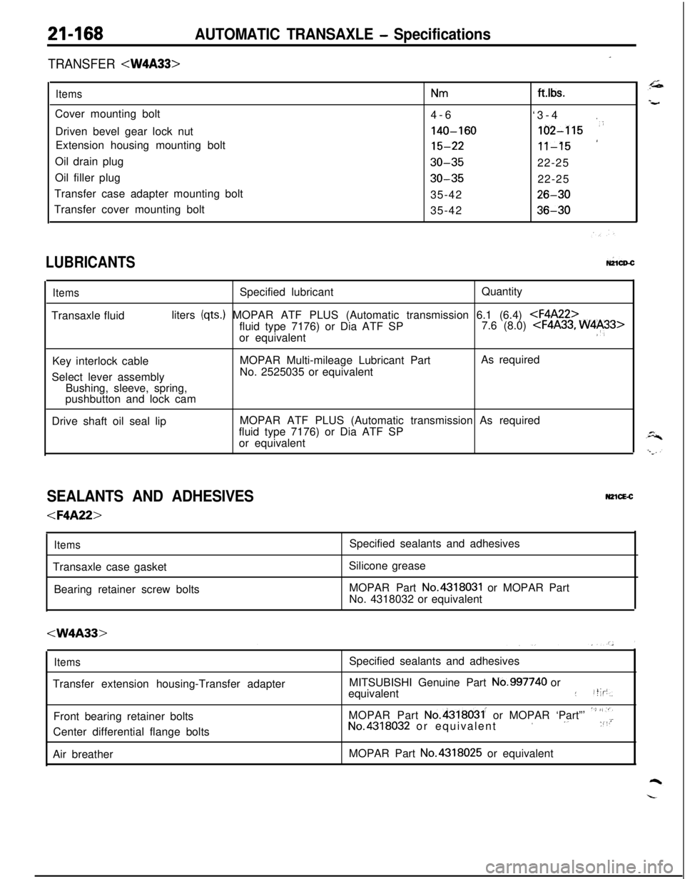
21-168AUTOMATIC TRANSAXLE - Specifications
-TRANSFER
ItemsNmCover mounting bolt
4-6
Driven bevel gear lock nut
140-160Extension housing mounting bolt
15-22Oil drain plug
30-35Oil filler plug
30-35Transfer case adapter mounting bolt
35-42
Transfer cover mounting bolt
35-42ft.lbs.
‘3-4
.
162-115 ‘i
‘11-1522-25
22-25
26-30
36-30
LUBRICANTSW1CD-C
ItemsSpecified lubricantQuantity
Transaxle fluidliters
(qts.) MOPAR ATF PLUS (Automatic transmission 6.1 (6.4)
or equivalent
:‘,Key interlock cableMOPAR Multi-mileage Lubricant PartAs required
Select lever assemblyNo. 2525035 or equivalent
Bushing, sleeve, spring,
pushbutton and lock cam
Drive shaft oil seal lipMOPAR ATF PLUS (Automatic transmission As required
fluid type 7176) or Dia ATF SP
or equivalent
SEALANTS AND ADHESIVESN2lcE-c
ItemsTransaxle case gasket
Bearing retainer screw bolts
Silicone grease
MOPAR Part
No.4318031 or MOPAR Part
No. 4318032 or equivalent
ItemsTransfer extension housing-Transfer adapter
Front bearing retainer bolts
Center differential flange bolts
Air breatherSpecified sealants and adhesives
MITSUBISHI Genuine Part
No.997740 or
equivalent::t;p,
MOPAR Part
No.4318031. or MOPAR ‘Part”’ ‘~’ “,“iNo.4318032 or equivalent’ ‘. :“’MOPAR Part No.4318025 or equivalent
Page 918 of 1216
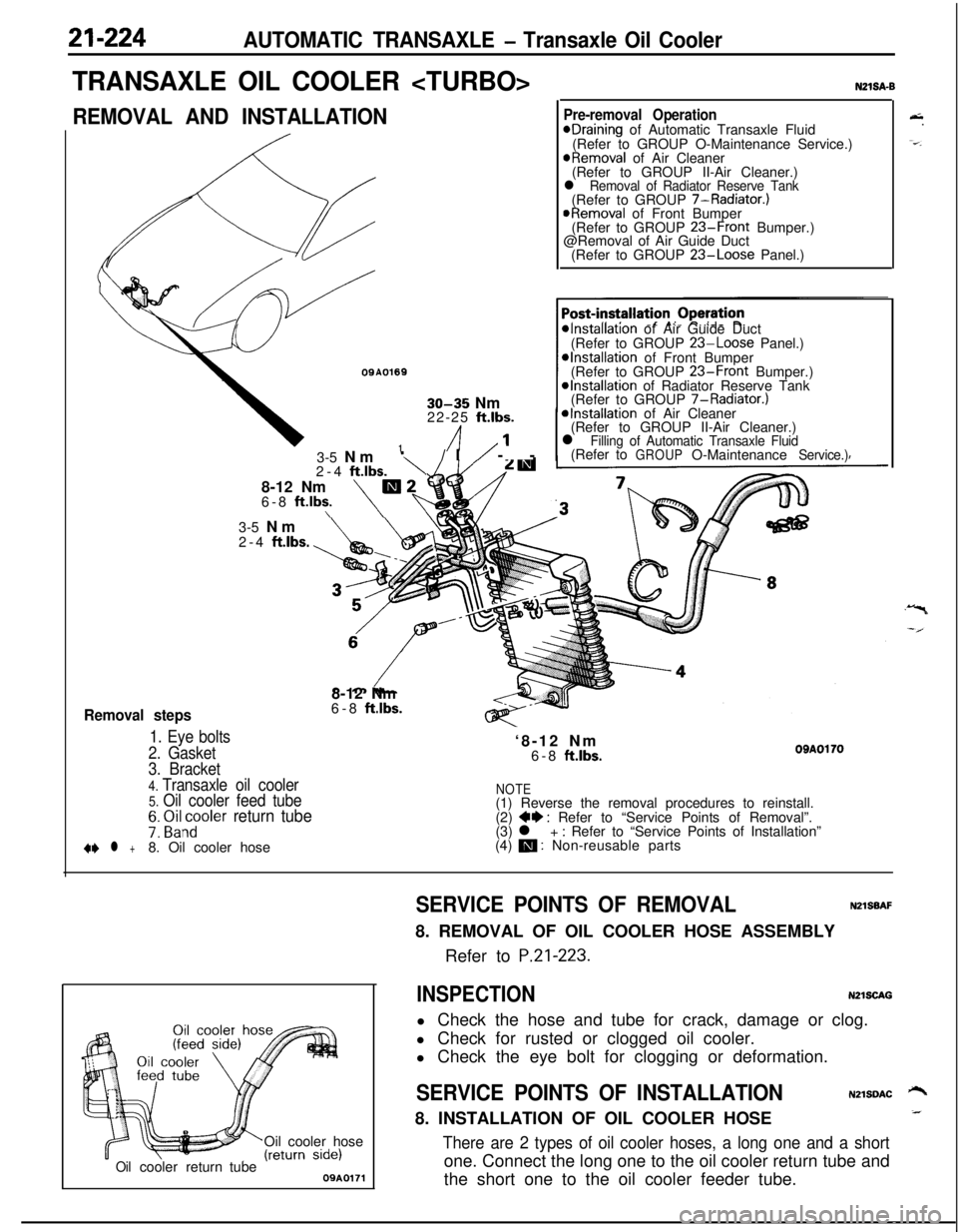
21-224AUTOMATIC TRANSAXLE - Transaxle Oil Cooler
TRANSAXLE OIL COOLER
REMOVAL AND INSTALLATION
OQA01691
30-35 Nm
22-25 ft.lbs.
/I1’
Removal steps
1. Eye bolts
2. Gasket3-5 Nm
‘\/I/ --
2-4
ftlbs.8-12 Nm
m26-8 ft.lbs.\\
N21SA-B
Pre-removal OperationeDraining of Automatic Transaxle Fluid
(Refer to GROUP O-Maintenance Service.)
@Removal of Air Cleaner
(Refer to GROUP II-Air Cleaner.)
l Removal of Radiator Reserve Tank(Refer to GROUP 7-Radiator.)
@Removal of Front Bumper
(Refer to GROUP 23-Front Bumper.)
@Removal of Air Guide Duct
(Refer to GROUP
23-Loose Panel.)
*Installation of Air Guide Duct
(Refer to GROUP 23-Loose Panel.)*Installation of Front Bumper
(Refer to GROUP 23-Front Bumper.)@Installation of Radiator Reserve Tank
(Refer to GROUP 7-Radiator.)
*Installation of Air Cleaner
(Refer to GROUP II-Air Cleaner.)
l Filling of Automatic Transaxle Fluid(Refer toGROUPO-MaintenanceService.)3-5 Nm
2-4
ftlbs.8-12 Nm
6-8
ft.lbs.‘8-12 Nm
6-8
ftlbs.OBAOl703. Bracket
4. Transaxle oil cooler5. Oil cooler feed tubeNOTE(1) Reverse the removal procedures to reinstall.
7: ~i&~oler return tube(2) ++ : Refer to “Service Points of Removal”.
(3) l + : Refer to “Service Points of Installation”
+e l +8. Oil cooler hose(4) m : Non-reusable parts
Oil cooler hose
Oilcoolerreturn tube09A0171
&.
-=-.
SERVICE POINTS OF REMOVALNZlSBAF8. REMOVAL OF OIL COOLER HOSE ASSEMBLY
Refer to
P.21-223.
INSPECTIONN2lSCAGl Check the hose and tube for crack, damage or clog.
l Check for rusted or clogged oil cooler.
l Check the eye bolt for clogging or deformation.
SERVICE POINTS OF INSTALLATIONN2lSDAC ‘-+8. INSTALLATION OF OIL COOLER HOSE_
There are 2 types of oil cooler hoses, a long one and a shortone. Connect the long one to the oil cooler return tube and
the short one to the oil cooler feeder tube.
Page 1046 of 1216
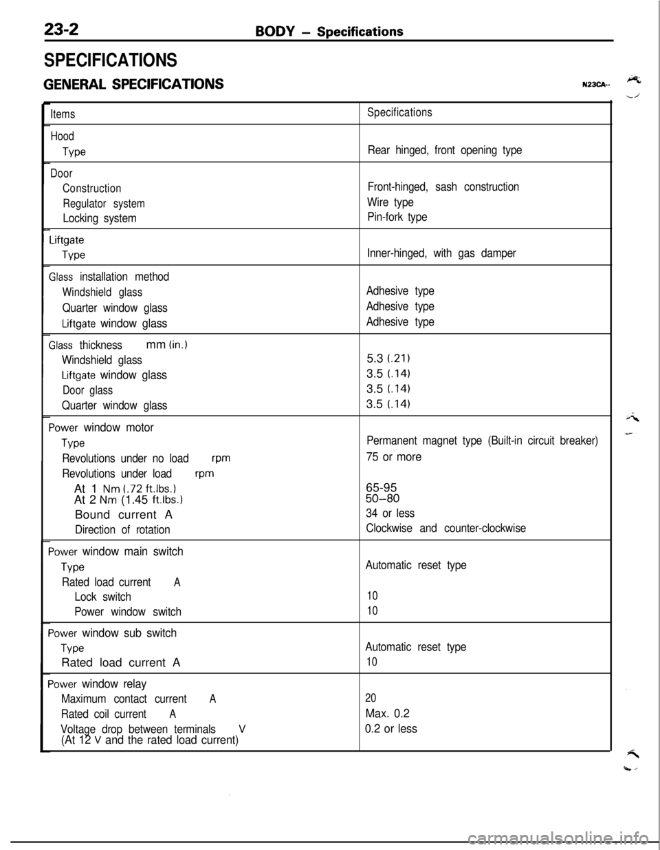
23-2
SPECIFICATIONS
GENERAL SPECIFICATIONS
BODY - Specifications
N23CA--
Items
Hood
We
Door
Construction
Regulator system
Locking system
Liftgate
We
Slass installation method
Windshield glass
Quarter window glass
Liftgate window glass
Zlass thicknessmm (in.)
Windshield glass
Liftgate window glass
Door glass
Quarter window glass
‘ower window motor
Type
Revolutions under no loadwm
Revolutions under load
wmAt 1
Nm t.72 ft.lbs.1At 2
Nm (1.45 ft.lbs.1Bound current A
Direction of rotation
‘ower window main switch
Type
Rated load currentA
Lock switch
Power window switch
‘ower window sub switch
TvwRated load current A
‘ower window relay
Maximum contact currentA
Rated coil currentA
Voltage drop between terminalsV(At 12 V and the rated load current)
Specifications
Rear hinged, front opening type
Front-hinged, sash construction
Wire type
Pin-fork type
Inner-hinged, with gas damper
Adhesive type
Adhesive type
Adhesive type5.3
i.21)3.5
t.1413.5
t.1413.5
t.141
Permanent magnet type (Built-in circuit breaker)
75 or more65-95
50-80
34 or less
Clockwise and counter-clockwise
Automatic reset type
10
10
Automatic reset type
10
20
Max. 0.2
0.2 or less
Page 1085 of 1216
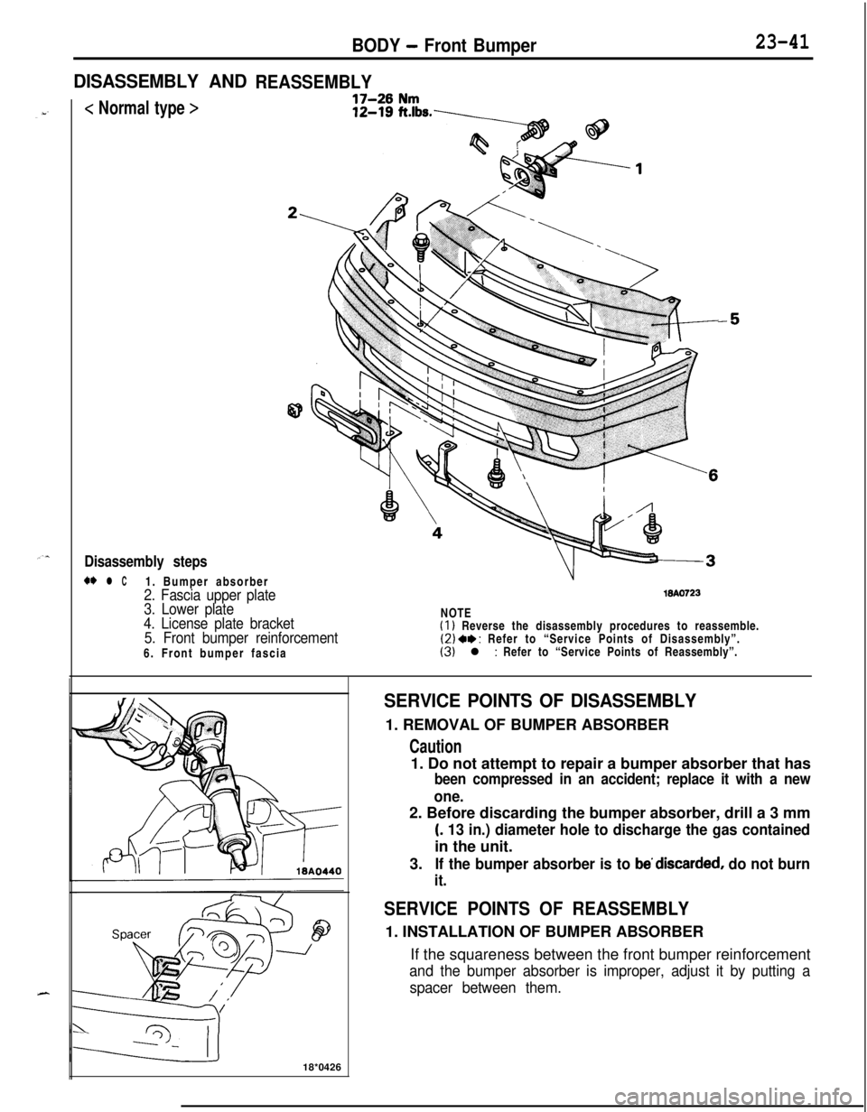
BODY - Front Bumper23-41
DISASSEMBLY ANDREASSEMBLY
< Normal type >
-
Disassembly steps
w l C1. Bumper absorber
2. Fascia upper plate
3. Lower plate18AO723
4. License plate bracket
5. Front bumper reinforcement6. Front bumper fasciaNOTE(1) Reverse the disassembly procedures to reassemble.(2) 4, : Refer to “Service Points of Disassembly”.(3) l : Refer to “Service Points of Reassembly”.
18*0426
SERVICE POINTS OF DISASSEMBLY1. REMOVAL OF BUMPER ABSORBER
Caution1. Do not attempt to repair a bumper absorber that has
been compressed in an accident; replace it with a new
one.2. Before discarding the bumper absorber, drill a 3 mm
(. 13 in.) diameter hole to discharge the gas containedin the unit.
3.
If the bumper absorber is to be’discarded, do not burn
it.
SERVICE POINTS OF REASSEMBLY1. INSTALLATION OF BUMPER ABSORBER
If the squareness between the front bumper reinforcement
and the bumper absorber is improper, adjust it by putting a
spacer between them.
Page 1086 of 1216
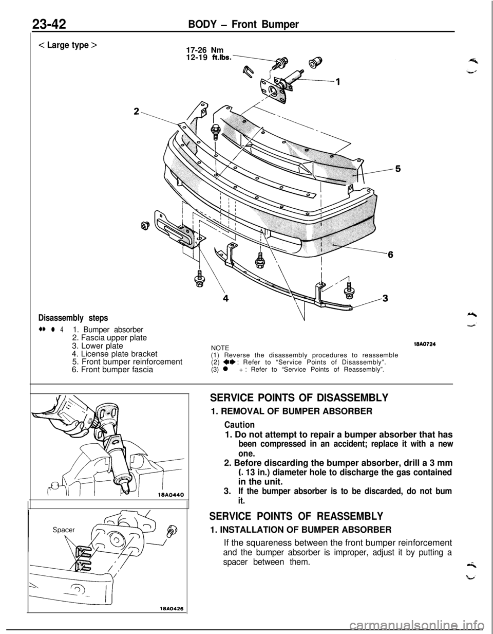
23-42BODY - Front Bumper
< Large type >
17-26 Nm
12-19
ftlbs.
Disassembly steps
** l 41. Bumper absorber2. Fascia upper plate
3. Lower plate
4. License plate bracket
5. Front bumper reinforcement
6. Front bumper fasciaNOTE
(1) Reverse the disassembly procedures to reassemble
(2)
+e : Refer to “Service Points of Disassembly”.
(3) l + : Refer to “Service Points of Reassembly”.WA0724
18410426
SERVICE POINTS OF DISASSEMBLY1. REMOVAL OF BUMPER ABSORBER
Caution1. Do not attempt to repair a bumper absorber that has
been compressed in an accident; replace it with a new
one.2. Before discarding the bumper absorber, drill a 3 mm
(. 13 in.) diameter hole to discharge the gas containedin the unit.
3.
If the bumper absorber is to be discarded, do not bum
it.
SERVICE POINTS OF REASSEMBLY1. INSTALLATION OF BUMPER ABSORBER
If the squareness between the front bumper reinforcement
and the bumper absorber is improper, adjust it by putting a
spacer between them.
Page 1089 of 1216

BODY - Rear Bummer23-45
DISASSEMBLY AND REASSEMBLY<
Normal type >
Disassembly steps1. License plate light
2. Back-up light
3. Rear side marker light
4. License plate light wiring harness
5. Bumper absorber
6. Rear bumper reinforcement
7. License plate bracket
8. Rear bumper fasciaNOTE
(1) Reverse the disassembly procedures to reassemble.(2) +* : Refer to “Service Points of Disassembly”.
SERVICE POINTS OF DISASSEMBLY5. REMOVAL OF BUMPER ABSORBER
Caution1. Do not attempt to repair a bumper absorber that has
been compressed in an accident; replace it with a new
one.2. Before discarding the bumper absorber, drill a 3 mm
(. 13 in.) diameter hole to discharge the gas containedin the unit.
3.
If the bumper absorber is to be discarded, do not burn
it.