torque specification MITSUBISHI ECLIPSE 1991 User Guide
[x] Cancel search | Manufacturer: MITSUBISHI, Model Year: 1991, Model line: ECLIPSE, Model: MITSUBISHI ECLIPSE 1991Pages: 1216, PDF Size: 67.42 MB
Page 249 of 1216
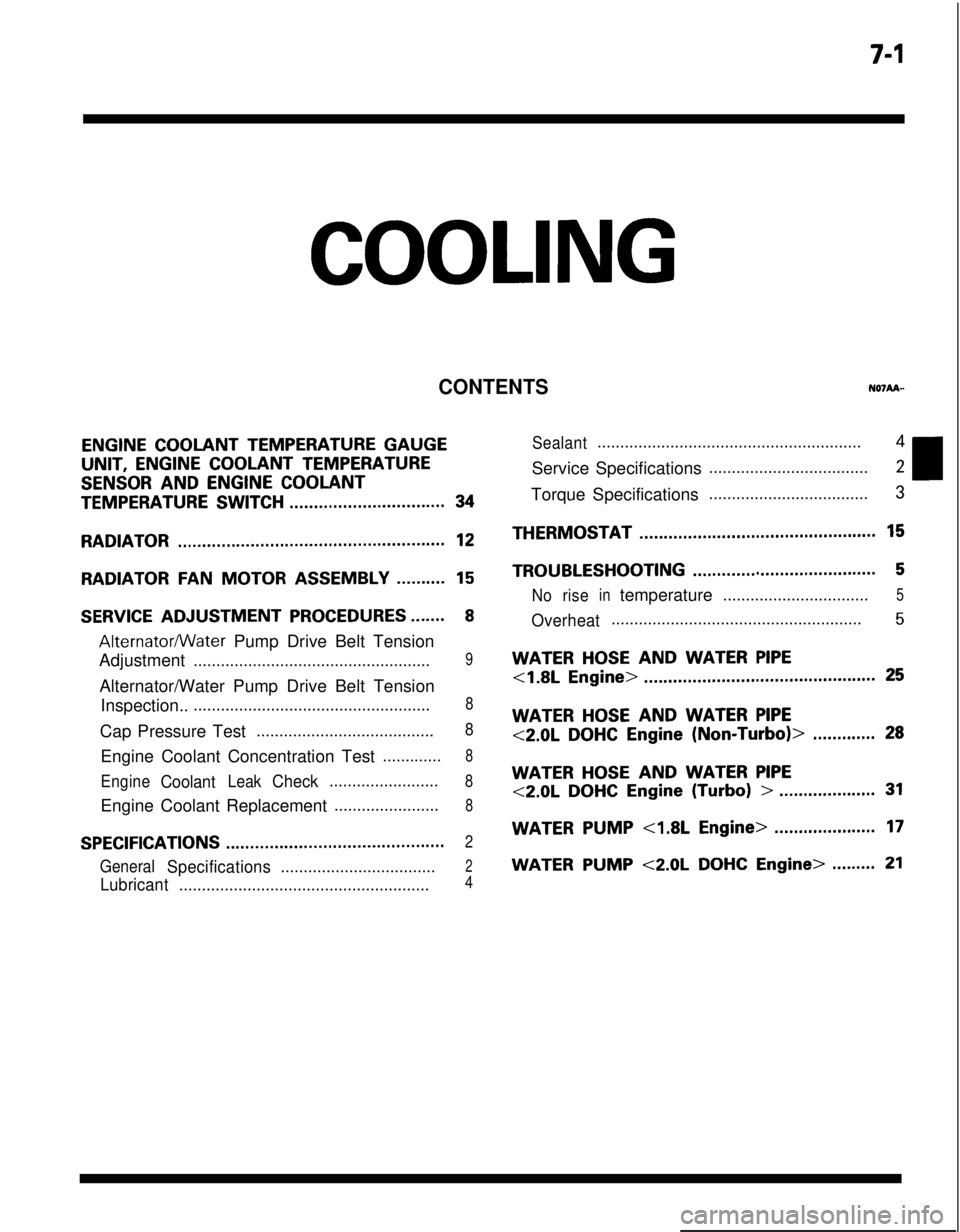
7-l
COOLING
CONTENTS
ENGINE COOLANT TEMPERATURE GAUGEUNIT,
ENGINE COOLANT TEMPERATURE
SENSOR AND ENGINE COOLANT
TEMPERATURE SWITCH................................34
RADIATOR.......................................................12
RADIATORFANMOTOR ASSEMBLY..........15
SERVICE ADJUSTMENT PROCEDURES.......8
Alternatormater Pump Drive Belt Tension
Adjustment
....................................................9Alternator/Water Pump Drive Belt Tension
Inspection..
....................................................8Cap Pressure Test
.......................................8Engine Coolant Concentration Test
.............8
EngineCoolantLeakCheck........................8Engine Coolant Replacement
.......................8
SPECIFICATIONS.............................................2
GeneralSpecifications..................................2
Lubricant.......................................................4
Sealant..........................................................4Service Specifications
...................................2Torque Specifications
...................................3THERMOSTAT
.................................................15
TROUBLESHOOTING......................................5
Noriseintemperature................................5
Overheat.......................................................5
WATER HOSE AND WATER PIPE
<1.8L Engine>................................................25
WATER HOSE AND WATER PIPE
<2.0LDOHCEngine(Non-Turbo)>.............28
WATER HOSE AND WATER PIPE
<2.0LDOHCEngine(Turbo)>....................31
WATERPUMP<1.8LEngine>.....................17
WATER PUMP <2.0L DOHC Engine>.........21
Page 251 of 1216
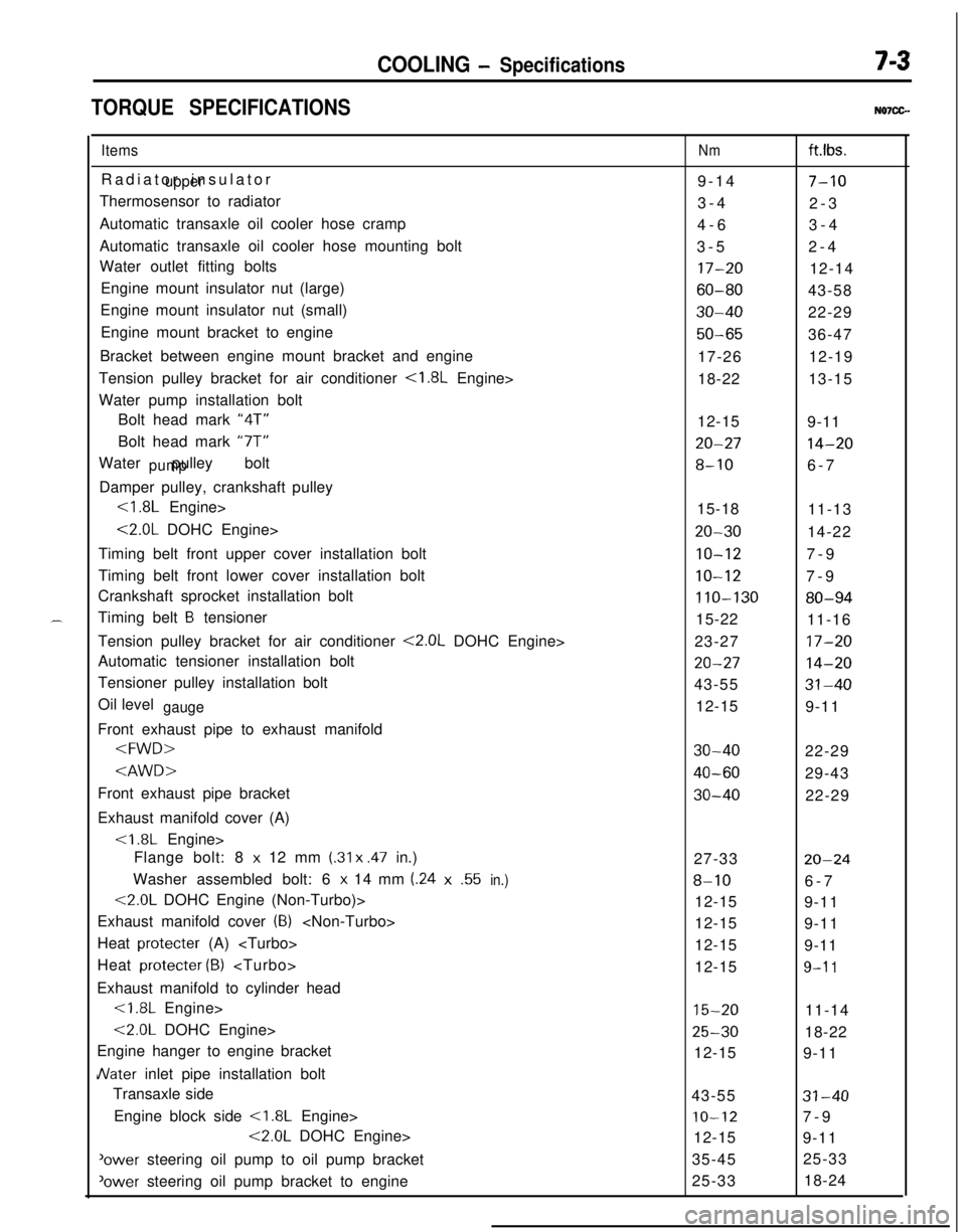
COOLING - Specifications7-3
TORQUE SPECIFICATIONSN07CG.
ItemsRadiator insulator
upperThermosensor to radiator
Automatic transaxle oil cooler hose cramp
Automatic transaxle oil cooler hose mounting bolt
Water outlet fitting bolts
Engine mount insulator nut (large)
Engine mount insulator nut (small)
Engine mount bracket to engine
Bracket between engine mount bracket and engine
Tension pulley bracket for air conditioner
<1.8L Engine>
Water pump installation bolt
Bolt head mark “4T”
Bolt head mark “7T”
Water pulley bolt
pumpDamper pulley, crankshaft pulley
<1.8L Engine>
<2.0L DOHC Engine>
Timing belt front upper cover installation bolt
Timing belt front lower cover installation bolt
Crankshaft sprocket installation bolt
Timing belt
B tensioner
Tension pulley bracket for air conditioner
<2.0L DOHC Engine>
Automatic tensioner installation bolt
Tensioner pulley installation bolt
Oil level
gaugeFront exhaust pipe to exhaust manifold
Exhaust manifold cover (A)
Flange bolt: 8
x 12 mm (.31 x .47 in.)
Washer assembled bolt: 6
x 14 mm (.24x.55in.)
<2.0L DOHC Engine (Non-Turbo)>
Exhaust manifold cover
(8)
Heat protecter (A)
Heat protecter
(B)
Exhaust manifold to cylinder head<1.8L Engine>
<2.0L DOHC Engine>
Engine hanger to engine bracket
JVater inlet pipe installation bolt
Transaxle side
Engine block side
<1.8L Engine>
<2.0L DOHC Engine>
'ower steering oil pump to oil pump bracket
‘ower steering oil pump bracket to engine
Nmft.lbs.
9-14
7-103-4
2-3
4-63-4
3-52-4
17-2012-14
60-8043-58
30-4022-29
50-6536-47
17-2612-19
18-2213-15
12-15
9-11
20-2714-20
8-106-7
15-18
11-13
20-3014-22
IO-127-9
10-127-9
110-13080-9415-22
11-16
23-27
17-20
20-2714-2043-55
31-4012-15
9-11
30-4022-29
40-6029-43
30-4022-29
27-33
20-24
8-106-7
12-15
9-11
12-15
9-11
12-15
9-11
12-15
9-l 1
15-2011-14
25-3018-22
12-15
9-11
43-55
31-40
IO-127-9
12-15
9-11
35-4525-33
25-3318-24
Page 285 of 1216
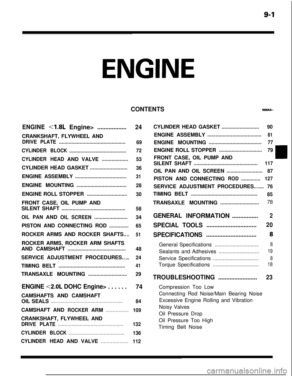
9-1
ENGINE
CONTENTSNOSAA-
ENGINE<1.8L
Engine>..................
24CRANKSHAFT, FLYWHEEL AND
DRIVE PLATE................................................
69
CYLINDER
BLOCK.........................................72
CYLINDERHEADANDVALVE
...................
53CYLINDER HEAD GASKET
...........................
36ENGINE ASSEMBLY
.....................................31ENGINE MOUNTING
....................................
28ENGINE ROLL STOPPER
.............................
30FRONT CASE, OIL PUMP AND
SILENT SHAFT
..............................................
58
OILPANANDOILSCREEN........................34
PISTON AND CONNECTING ROD
..............
65ROCKER ARMS AND ROCKER SHAFTS..
..51ROCKER ARMS, ROCKER ARM SHAFTS
AND CAMSHAFT
..........................................48
SERVICE ADJUSTMENT PROCEDURES..
...24TIMING BELT
................................................41TRANSAXLE MOUNTING
............................
29
ENGINE <2.0L DOHC Engine> . . . . . .
74CAMSHAFTS AND CAMSHAFT
OIL SEALS
. . . . . . . . . . . . . . . . . . . . . . . . . . . . . . . . . . . . . . . . . . . . . . . . . . . . .84CAMSHAFTAND
ROCKERARM. . . . . . . . . . . . . . . .109CRANKSHAFT, FLYWHEEL AND
DRIVE PLATE. . . . . . . . . . . . . . . . . . . . . . . . . . . . . . . . . . . . . . . . . . . . . . . .132
CYLINDERBLOCK. . . . . . . . . . . . . . . . . . . . . . . . . . . . . . . . . . . . . . . . .136
CYLINDERHEADANDVALVE
. . . . . . . . . . . . . . . . . . .112CYLINDER HEAD GASKET
...........................90ENGINE ASSEMBLY
.......................................81ENGINE MOUNTING
......................................77ENGINE ROLL STOPPER
...............................
79FRONT CASE, OIL PUMP AND
SILENT SHAFT
..............................................117OIL PAN AND OIL SCREEN
..........................
87
PISTONANDCONNECTING
ROD..............127SERVICE ADJUSTMENT PROCEDURES..
.....76TIMING BELT
................................................
85TRANSAXLE MOUNTING
............................78
GENERALINFORMATION................2
SPECIAL TOOLS...............................20
SPECIFICATIONS...............................8General Specifications
................................8Sealants and Adhesives
.............................19Service Specifications
.................................8Torque Specifications
.................................18
TROUBLESHOOTING........................23Compression Too Low
Connecting Rod Noise/Main Bearing Noise
Excessive Engine Rolling and Vibration
Noisy Valves
Oil Pressure Drop
Oil Pressure Too High
Timing Belt Noise
Page 302 of 1216
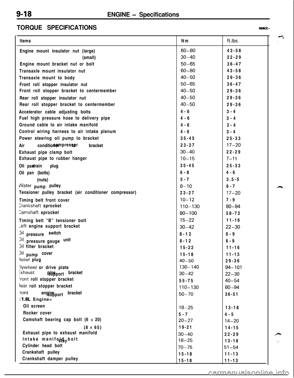
9-18ENGINE - Specifications
TORQUE SPECIFICATIONS
NO9CG-Items
Engine mount insulator nut (large)
(small)
Engine mount bracket nut or bolt
Transaxle mount insulator nut
Transaxle mount to body
Front roll stopper insulator nut
Front roll stopper bracket to centermember
Rear roll stopper insulator nut
Rear roll stopper bracket to centermember
Accelerator cable adjusting bolts
Fuel high pressure hose to delivery pipe
Ground cable to air intake manifold
Control wiring harness to air intake plenum
Power steering oil pump to bracket
Air conditioner to bracketcompressor
Exhaust pipe clamp bolt
Exhaust pipe to rubber hanger
Oil drain plug
panOil (bolts)
pan(nuts)VVater pulley
pump
Tensioner pulley bracket (air conditioner compressor)
Timing belt front coverCrankshaft sprocket
Camshaft sprocket
Timing belt “B” tensioner bolt
-eft engine support bracket3il switch
pressure3il unit
pressure gauge
Iii filter bracket
Iii cover
pumpqelief plug
‘lywheel or drive plate
ixhaust pipe bracket
support
‘rant roll stopper bracket
Iear roll stopper bracket‘rant engine bracket
support
:1.8L Engine>
Oil screen
Rocker cover
Camshaft bearing cap bolt (6 x 20)
(8 x 65)
Exhaust pipe to exhaust manifold
Intake manifold bolt
stay
Cylinder head bolt
Crankshaft pulley
Crankshaft damper pulleyNm
ftlbs.
60-8043-58
30-4022-29
50-6536-47
60-8043-58
40-5029-36
50-6536-47
40-5029-36
40-5029-36
40-5029-36
4-63-4
4-6
3-4
4-6
3-4
4-6
3-4
35-45
25-33
23-27
17-20
30-4022-29
10-157-l 135-45
25-33
6-84-6
5-73.5-5
8-106-7
23-27
17-20
10-127-9
110-13080-94
80-10058-72
15-2211-16
30-4222-308-126-9
8-126-9
15-2211-16
15-1811-13
40-5029-36
130-14094-101
30-4222-3055-75
40-54
110-13080-94
50-7036-51
18-2513-18
5-74-5
20-2714-2019-21
14-15
30-4022-29
18-2513-18
70-7551-5415-1811-13
15-1811-13
Page 386 of 1216
S-102ENGINE <2.0L DOHC Engine> - Timing Belt
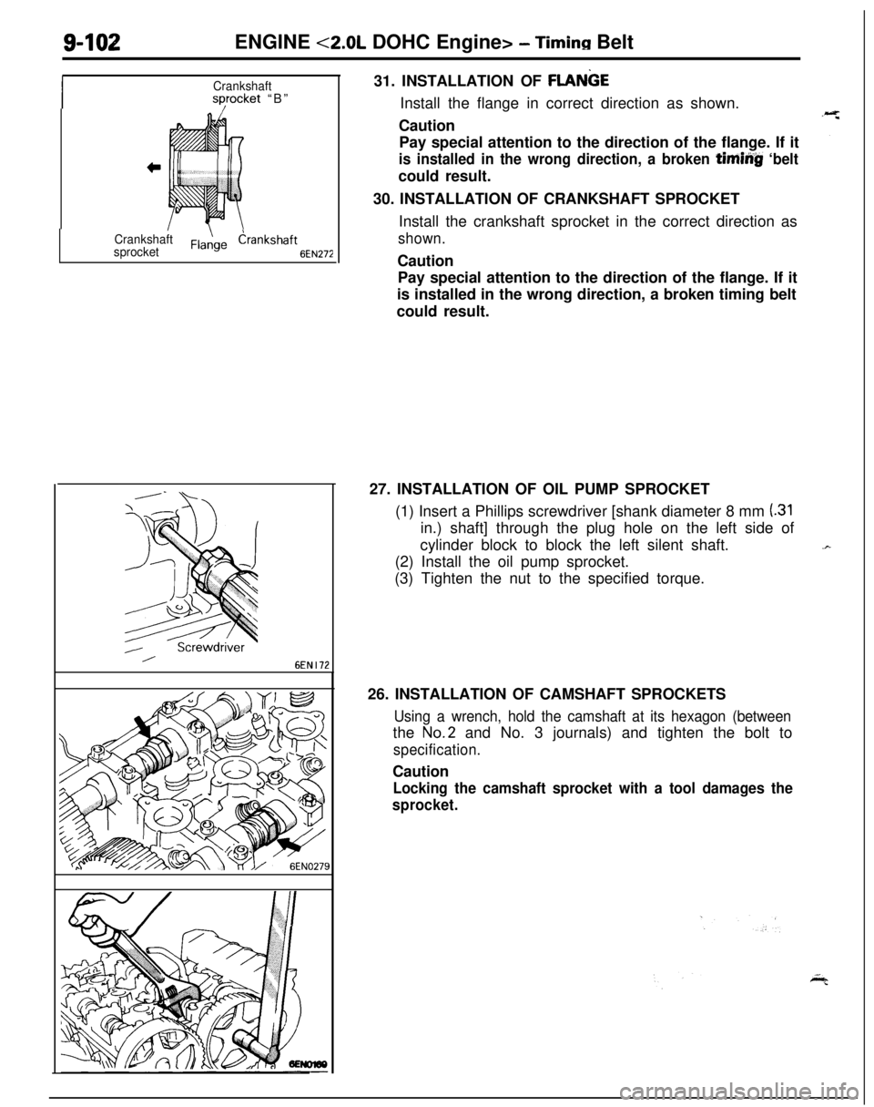
Crankshaftsyocket “B”
Crankshaft
sprocketdrankshaft 6fN272
6EN I1231. INSTALLATION OF
FLANGEInstall the flange in correct direction as shown.
Caution
Pay special attention to the direction of the flange. If it
is installed in the wrong direction, a broken timiiig ‘beltcould result.
30. INSTALLATION OF CRANKSHAFT SPROCKET
Install the crankshaft sprocket in the correct direction as
shown.Caution
Pay special attention to the direction of the flange. If it
is installed in the wrong direction, a broken timing belt
could result.
27. INSTALLATION OF OIL PUMP SPROCKET
(1) Insert a Phillips screwdriver [shank diameter 8 mm
(.31in.) shaft] through the plug hole on the left side of
cylinder block to block the left silent shaft.
(2) Install the oil pump sprocket.
(3) Tighten the nut to the specified torque.
26. INSTALLATION OF CAMSHAFT SPROCKETS
Using a wrench, hold the camshaft at its hexagon (betweenthe
No.2 and No. 3 journals) and tighten the bolt to
specification.Caution
Locking the camshaft sprocket with a tool damages the
sprocket.
Page 390 of 1216
9-106ENGINE <2.0L DOHC Engine> - Timing Belt. ADJUSTMENT OF TIMING BELT TENSION
(1) After turning the crankshaft
l/4 turn counterclockwise,.5;;turn it clockwise to move the No. 1 cylinder to top dead
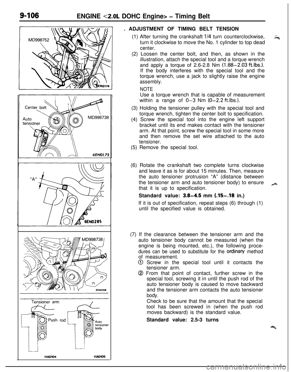
center.(2) Loosen the center bolt, and then, as shown in the
illustration, attach the special tool and a torque wrench
and apply a torque of 2.6-2.8 Nm
(1.88-2.03 ft.lbs.).If the body interferes with the special tool and the
torque wrench, use a jack to slightly raise the engine
assembly.
NOTEUse a torque wrench that is capable of measurement
within a range of
O-3 Nm (O-2.2 ft.lbs.).(3) Holding the tensioner pulley with the special tool and
torque wrench, tighten the center bolt to specification.
(4) Screw the special tool into the engine left support
bracket until its end makes contact with the tensioner
arm. At that point, screw the special tool in some more
and then remove the set wire attached to the auto
tensioner.(5) Remove the special tool.
(6) Rotate the crankshaft two complete turns clockwise
and leave it as is for about 15 minutes. Then, measure
the auto tensioner protrusion “A” (distance between
the tensioner arm and auto tensioner body) to ensure,.+
that it is up to specification.
Standard value:
3.8-4.5 mm (.15-.18 in.)
If it is out of specification, repeat steps (6) through (1)
until the specified value is obtained.
(7) If the clearance between the tensioner arm and the
auto tensioner body cannot be measured (when the
engine is being mounted, etc.), the following proce-
dures can be used to substitute for the ordinan/ methodof measurement.
@ Screw in the special tool until it contacts the
tensioner arm.
@ From that point of contact, further screw in the
special tool, screwing it in until the push rod of the
auto tensioner body is caused to move backward
and the tensioner arm contacts the auto tensioner
body.Check to be sure that the amount that the special
tool has been screwed in (when the push rod
moves backward) is the standard value.
Standard value: 2.5-3 turns
Page 409 of 1216
ENGINE <2.0L DOHC Engine> -Front Case, Oil Pump and Silent Shaft9-1256E
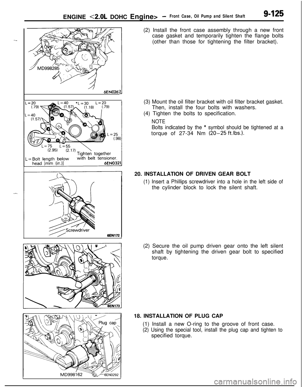
N026:(2) Install the front case assembly through a new front
case gasket and temporarily tighten the flange bolts
(other than those for tightening the filter bracket).
(3) Mount the oil filter bracket with oil filter bracket gasket.
Then, install the four bolts with washers.
(4) Tighten the bolts to specification.
NOTE
Bolts indicated by the * symbol should be tightened at atorque of 27-34 Nm
(20-25 ft.1b.s.).20. INSTALLATION OF DRIVEN GEAR BOLT
(1) Insert a Phillips screwdriver into a hole in the left side ofthe cylinder block to lock the silent shaft.
(2) Secure the oil pump driven gear onto the left silent
shaft by tightening the driven gear bolt to specified
torque.18. INSTALLATION OF PLUG CAP
(1) Install a new O-ring to the groove of front case.
(2) Using the special tool, install the plug cap and tighten tospecified torque.
Page 423 of 1216
11-l
INTAKE AND
EXHAUSTAIR CLEANER
. . . . . . . ..*........................................8
EXHAUST MANIFOLD <1.8L Engine> . . . . . . . .26
EXHAUST MANIFOLD
<2.0L DOHC Engine
(Non-Turbo)>
. . . . . . ..*.*.......................................27EXHAUST MANIFOLD
<2.0L DOHC Engine
(Turbo)>
. . . . . . . . . . . . . . . . . . . . . . . . . . . . . .*...........................28
CONTENTSNllAA--
-EXHAUST PIPE AND MAIN MUFFLER<1.8L Engine,
2.0L DOHC Engine
(Non-Turbo)>
. . . . . . . . . . . . . . . . . . . . .. . . . . . . . . . . . . . . . . . . . . . . . . . . . .30EXHAUST PIPE AND MAIN MUFFLER<2.0L
DOHCEngine(Turbo)>. . . . . . . . . . . . . . . . . . . . .31INTAKE MANIFOLD
<1.8LEngine> . . . . . . . . . . . .13INTAKE MANIFOLD
<2.0L DOHC Engine> 17
INTERCOOLER. . . . . . . . . . . . . . . . . . . . . . . . . . . . . . . . . . . . . . . . . . . . . . . . .11SERVICE ADJUSTMENT PROCEDURES..
.....5Air
Bypass ValveInspection........................7Air Cleaner Element Inspection and
Replacement . .
. . . . . . . . . . . . . . . . . . . . . . . . . . . . . . . . . . . . . . . . . . . . .5Supercharging Pressure Control System
Inspection
.,...... . . . . . . . . . . . . . . . . . . . . . . . . . . . . . . . .. . . . . . . . . . . . . .6Supercharging Pressure Relief Solenoid
Valve Inspection
. . . . . . . . . . . . . . . . . . . . . . . . . . . . . . . . . . . . . . . . . . .7Turbocharger Supercharging Pressure
Inspection. . . . . . . . . . . . . . . . . . . . . . . . . . . . . . . . . . . . . . . . . . . . . . . . . . . . . .6SPECIAL TOOL
. . . . . . . . . . . . . . . . . . . . . . . . . . . . . ..#................4
SPECIFICATIONS.............................................2General Specifications
..................................2Service Specifications
...................................2Torque Specifications
...................................2
TROUBLESHOOTING. . . . . . . . . . . . . . . . . . . . . . . . . . . . . . . . . . . . . .4
Abnormal Noise
Exhaust Gas Leakage
TURBOCHARGER
. . . . . . . . . . . . . . . . . . . . . . . . . . . . . . . . . . . . . . . . . . . .20
Page 424 of 1216
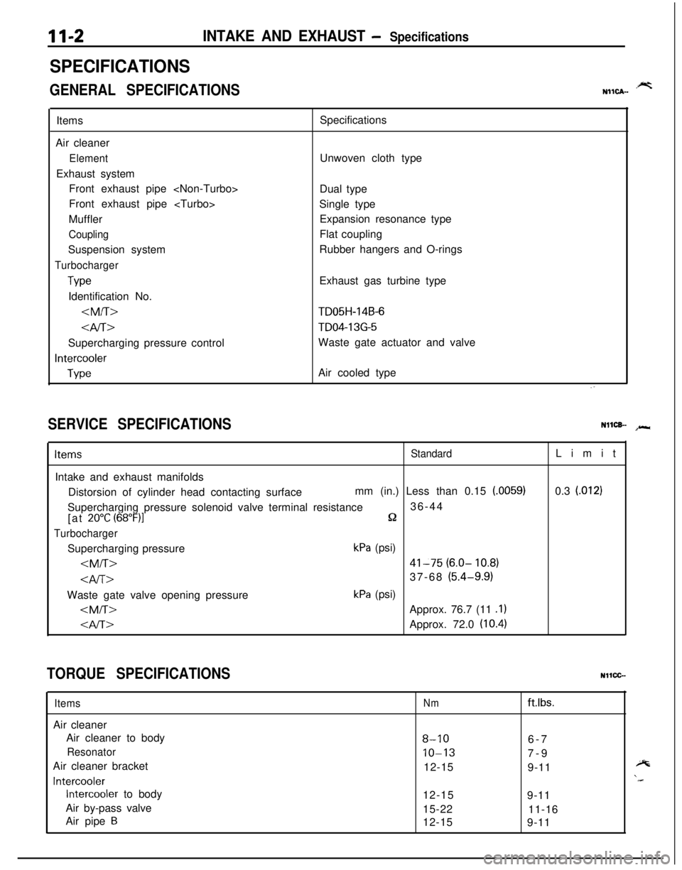
11-2INTAKE AND EXHAUST - Specifications
SPECIFICATIONS
GENERAL SPECIFICATIONS.prtNIICA-Items
Air cleaner
ElementExhaust system
Front exhaust pipe
Front exhaust pipe
Muffler
CouplingSuspension system
Turbocharger
TypeIdentification No.
4iT>Supercharging pressure control
Intercooler
TypeSpecifications
Unwoven cloth type
Dual type
Single type
Expansion resonance type
Flat coupling
Rubber hangers and O-rings
Exhaust gas turbine type
TD05H-14B-6
TD04-13G-5Waste gate actuator and valve
Air cooled type
SERVICE SPECIFICATIONSNllCB- spr*
ItemsStandardIntake and exhaust manifolds
Distorsion of cylinder head contacting surfacemm (in.) Less than 0.15
(.0059)Supercharging pressure solenoid valve terminal resistance36-44
[at
20°C (68”F)lQ
TurbochargerSupercharging pressure
kPa (psi)
kPa (psi)
0.3
l.0121
TORQUE SPECIFICATIONSNllCC-
ItemsAir cleaner
Air cleaner to body
ResonatorAir cleaner bracket
Intercooler
Intercooler to body
Air by-pass valve
Air pipe
B
Nmftlbs.
8-106-7
10-137-9
12-15
9-11
12-15
9-11
15-22
11-16
12-15
9-11
Page 455 of 1216
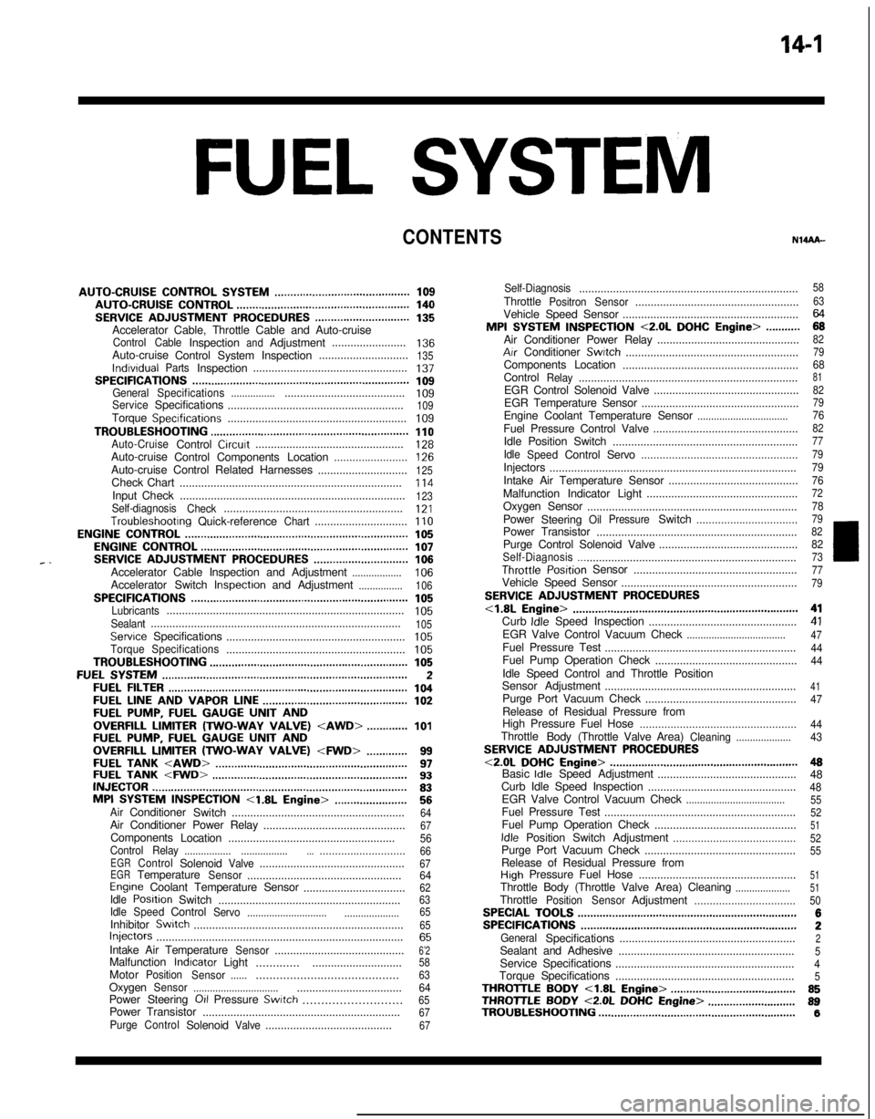
14-IFUEL SYSTEM
CONTENTS
AUTO-CRUISECONTROLSYSTEM...........................................109AUTO-CRUISECONTROL.......................................................140SERVICEADJUSTMENTPROCEDURES..............................135Accelerator Cable, Throttle Cable and Auto-cruise
ControlCableInspectionandAdjustment........................136Auto-cruise
ControlSystemInspection.............................135lndrvrdualPartsInspection..................................................137SPECIFICATIONS.....................................................................109GeneralSpecifications.......................................................109ServiceSpecifications
.........................................................109Torque Specrfications..........................................................109TROUBLESHOOTING...............................................................110Auto-CruiseControlCircurt................................................128Auto-cruise
ControlComponentsLocation........................126Auto-cruise Control Related Harnesses
.............................125Check Chart
........................................................................114Input Check.........................................................................123Self-diagnosis
Check..........................................................121Troubleshootrng
Quick-referenceChart..............................110ENGINECONTROL.......................................................................105ENGINECONTROL..................................................................107--SERVICEADJUSTMENTPROCEDURES..............................106Accelerator Cable Inspection and Adjustment..................106Accelerator Switch Inspectron and Adjustment................106SPECIFICATIONS.....................................................................105Lubricants.............................................................................105Sealant.................................................................................105ServiceSpecifications
..........................................................105TorqueSpecifications..........................................................105TROUBLESHOOTING...............................................................105FUELSYSTEM..............................................................................2FUELFILTER............................................................................104FUELLINEANDVAPORLINE..............................................102FUEL PUMP, FUEL GAUGE UNIT ANDOVERFILL LIMITER(TWO-WAY VALVE)
Switch........................................................64Air Conditioner Power Relay
..............................................67Components
Location......................................................56
ControlRelay
.................................................................66EGRControlSolenoidValve...............................................67EGRTemperatureSensor..................................................64Engine Coolant Temperature Sensor
.................................62IdlePosrtionSwitch
...........................................................63IdleSpeedControlServo
.............................
....................65InhibitorSwitch....................................................................65hjeCtOrS................................................................................65IntakeAirTemperatureSensor..........................................6’2MalfunctionlndtcatorLight
..........................................58MotorPosition
Sensor................................................63OxygenSensor
.................................................................64Power Steering 011 Pressure Swatch...........................65PowerTransistor
................................................................67PurgeControlSolenoidValve.........................................67
Self-Diagnosis.......................................................................
ThrottlePositronSensor.....................................................
Vehicle Speed Sensor.........................................................MPI
SYSTEMINSPECTION<2.0L DOHCEngine>...........Air Conditioner Power Relay..............................................
Arr Conditioner Swatch........................................................
Components Location
.........................................................
Control
Relay.......................................................................
EGR Control Solenoid Valve...............................................
EGR Temperature Sensor
...................................................
Engine Coolant Temperature Sensor
.................................Fuel Pressure Control Valve...............................................
Idle Position Switch
............................................................
Idle
SpeedControlServo...................................................Injectors
................................................................................
Intake Air Temperature Sensor..........................................
Malfunction Indicator Light.................................................
Oxygen Sensor
....................................................................
Power
Steering
OilPressureSwitch.................................Power Transistor
.................................................................
Purge Control Solenoid Valve.............................................
Self-Diaanosis.......................................................................
58
63
2382
79
688182
79
7682
77
79
79
76
727879
82
8273ThrottletiPosition Sensor
.....................................................77Vehicle Speed Sensor
.........................................................79SERVICE ADJUSTMENT PROCEDURES<1.8L Engine>........................................................................41Curb Idle Speed Inspection
................................................41EGR Valve Control Vacuum Check....................................47Fuel Pressure Test
..............................................................44Fuel Pump Operation Check
..............................................44Idle Speed Control and Throttle Position
Sensor Adjustment
..............................................................
41Purge Port Vacuum Check
.................................................47Release of Residual Pressure from
High Pressure Fuel Hose
...................................................
44Throttle
Body(Throttle Valve Area)Cleaning....................43SERVICE ADJUSTMENT PROCEDURES<2.0LDOHCEngine>............................................................48Basic Idle Speed Adjustment
.............................................
48
Curb Idle Speed Inspection
................................................48EGR Valve Control Vacuum Check....................................55Fuel Pressure Test
..............................................................52Fuel Pump Operation Check
..............................................51Idle Position Switch Adjustment........................................52Purge Port Vacuum Check
.................................................55Release of Residual Pressure from
High Pressure Fuel Hose
...................................................51Throttle Body (Throttle Valve Area) Cleaning....................51ThrottlePositionSensorAdjustment.................................50SPECIALTOOLS......................................................................6SPECIFICATIONS.....................................................................2GeneralSpecifications.........................................................2Sealant and Adhesive
.........................................................5Service Specifications
..........................................................4Torque Specifications
..........................................................5THROlTLEBODY<1.8LEngine>........................................85THROlTLE BODY <2.0L DOHC Engine>............................89TROUBLESHOOTING...............................................................6