torque specification MITSUBISHI ECLIPSE 1991 Owner's Manual
[x] Cancel search | Manufacturer: MITSUBISHI, Model Year: 1991, Model line: ECLIPSE, Model: MITSUBISHI ECLIPSE 1991Pages: 1216, PDF Size: 67.42 MB
Page 459 of 1216
FUEL SYSTEM - SDecifications14-5
-.
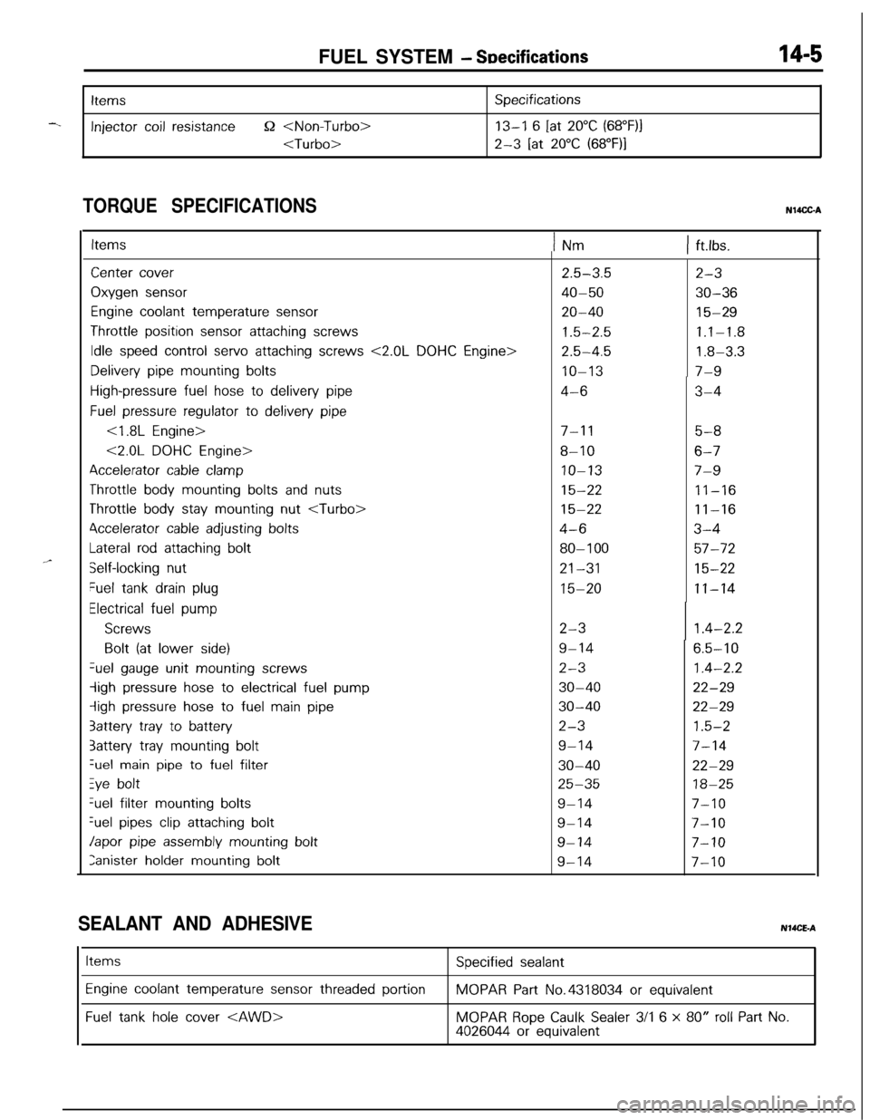
Items
Injector coil resistance52
Specifications
13-I 6 [at 20°C (68”F)j
2-3 [at 20°C (68”F)I
TORQUE SPECIFICATIONSN14CC-A
,,-
ItemsINm1 ft.lbs.
Center cover
Oxygen sensor
Engine coolant temperature sensor
Throttle position sensor attaching screws
Idle speed control servo attaching screws <2.0L DOHC Engine>
Delivery pipe mounting bolts
High-pressure fuel hose to delivery pipe
Fuel pressure regulator to delivery pipe
<1.8L Engine>
<2.0L DOHC Engine>
Accelerator cable clamp
Throttle body mounting bolts and nuts
Throttle body stay mounting nut
4ccelerator cable adjusting bolts
Lateral rod attaching bolt
Self-locking nut
Fuel tank drain plug
Electrical fuel pump
Screws
Bolt (at lower side)Gel
gauge unit mounting screws
-ligh pressure hose to electrical fuel pump
iigh pressure hose to fuel main pipe
3attery tray to battery
3attery tray mounting boltGel
main pipe to fuel filter
Zye boltGel filter
mounting bolts
%el pipes clip attaching bolt
Japor pipe assembly mounting bolt
Ianister holder mounting bolt
2.5-3.5
40-50
20-40
1.5-2.5
2.5-4.5
IO-13
4-6
7-l 15-8
8-106-7
IO-137-9
15-2211-16
15-2211-16
4-63-4
80-l 0057-72
21-3115-22
15-2011-14
2-3
9-14
2-3
30-40
30-40
2-3
9-14
30-40
25-35
9-14
9-14
9-14
9-14
2-3
30-36
15-29
1.1-1.8
1.8-3.3
7-9
3-4
1.4-2.2
6.5-10
1.4-2.2
22-29
22-29
1.5-2
7-14
22-29
18-25
7-10
7-10
7-10
7-10
SEALANT AND ADHESIVENMCE-A
Items
Engine coolant temperature sensor threaded portion
Fuel tank hole cover
Specified sealant
MOPAR Part No.4318034 or equivalent
MOPAR Rope Caulk Sealer 3/l 6 x 80” roll Part No.4026044 or equivalent
Page 517 of 1216
FUEL SYSTEM - MPI Svstem Inspection <1.8L Engine>18-63
Throttle position sensor
Groundoutput
Sensorpower
SUPPlY(5V)
1 FUO507
6FU1244Motor
Dosition sensor connector
(motor ‘side, front view)
T
6FU1247Motor position sensor
connector(motor side, front view)
6FU1252
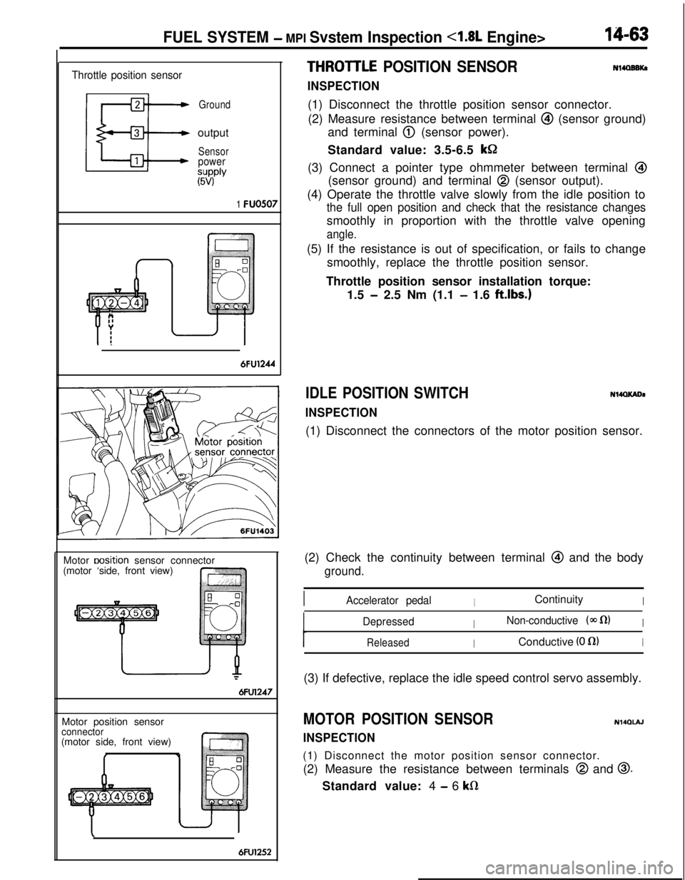
THROITLE POSITION SENSOR
INSPECTION
Nl4OBBKa(1) Disconnect the throttle position sensor connector.
(2) Measure resistance between terminal
@I (sensor ground)
and terminal
@ (sensor power).
Standard value: 3.5-6.5
kGI(3) Connect a pointer type ohmmeter between terminal
@(sensor ground) and terminal
@ (sensor output).
(4) Operate the throttle valve slowly from the idle position to
the full open position and check that the resistance changessmoothly in proportion with the throttle valve opening
angle.(5) If the resistance is out of specification, or fails to change
smoothly, replace the throttle position sensor.
Throttle position sensor installation torque:
1.5
- 2.5 Nm (1.1 - 1.6 ftlbs.)
IDLE POSITION SWITCH
INSPECTION
N14QKADa(1) Disconnect the connectors of the motor position sensor.
(2) Check the continuity between terminal
@ and the body
ground.
IAccelerator pedalIContinuityI
DepressedINon-conductive (@J fl)I
ReleasedIConductive (0 fl)I(3) If defective, replace the idle speed control servo assembly.
MOTOR POSITION SENSOR
INSPECTION
N140lAJ(1) Disconnect the motor position sensor connector.
(2) Measure the resistance between terminals
@ and 0.Standard value: 4
- 6 kfi
Page 531 of 1216
FUEL SYSTEM - MPI Svstem InsDection <2.0L DOHC Engine>14-77INSTALLATION
(1) Apply specified sealant to threaded portion and tighten to
specified torque.
Specified sealant: MOPAR Part No.4318034 or
equivalent
Specified torque: 20
- 40 Nm (15 - 29 ft.lbs.1(2) Fasten harness connectors securely.
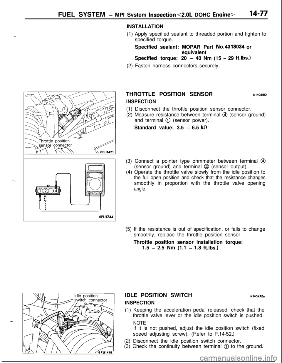
THROTTLE POSITION SENSOR
INSPECTION
N14QBBKl(1) Disconnect the throttle position sensor connector.
(2) Measure resistance between terminal
@I (sensor ground)
and terminal
@ (sensor power).
Standard value: 3.5
- 6.5 kR(3) Connect a pointer type ohmmeter between terminal
@I(sensor ground) and terminal
@ (sensor output).
(4) Operate the throttle valve slowly from the idle position to
the full open position and check that the resistance changessmoothly in proportion with the throttle valve opening
angle.
6FU1244(5) If the resistance is out of specification, or fails to change
smoothly, replace the throttle position sensor.
Throttle position sensor installation torque:
1.5
- 2.5 Nm (1.1 - 1.8 ft.lbs.)
J II\/ hFU1419IDLE POSITION SWITCH
INSPECTION
N14QKAEa(1) Keeping the acceleration pedal released, check that the
throttle valve lever or the idle position switch is pushed.
NOTEIf it is not pushed, adjust the idle position switch (fixed
speed adjusting screw). (Refer to
P.14-52.)(2) Disconnect the idle position switch connector.
(3) Check the continuity between terminal
@) to the ground.
Page 559 of 1216
ENGINE CONTROL - SpecificatiodTroubleshooting
ENGINE CONTROL
-.
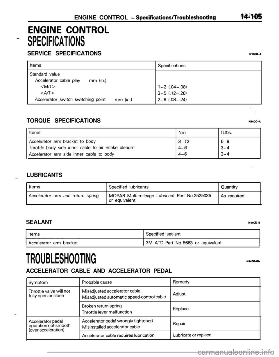
SPECIFICATIONS
SERVICE SPECIFICATIONSN14CEA
Items
Standard value
Accelerator cable playmm (in.)
dfi>
Accelerator switch switching pointmm (in.)Specifications
1-2 (.04-.08)
3-5 (.12-.20)
2-6 (.08-.24)
N14CkATORQUE SPECIFICATIONS
Items
Accelerator arm bracket to body
Throttle body side inner cable to air intake plenum
Accelerator arm side inner cable to body
Nmft.lbs.
8-126-9
4-63-4
4-63-4
I
: j,
LUBRICANTS_-
Items
Accelerator arm and return spring
Specified lubricants
MOPAR Multi-mileage Lubricant Part No.2525035
or equivalentQuantityAs required
SEALANTN14CE.-BItems
I-- ~Accelerator arm bracket
Specified sealant
I3M ATD Part No.8663 or equivalentI
-.
TROUBLESHOOTINGN14EGABa
ACCELERATOR CABLE AND ACCELERATOR PEDAL
Symptom
Throttle valve will notfully
open or close
Probable causeRemedyMisadjusted
accelerator cableMisadjusted automatic
speed-control cableAdjust
Broken return springThrottle
lever malfunctionReplace
Accelerator pedaloperation not smooth(over acceleration)
Accelerator pedal wrongly tightenedMisinstalled
accelerator cable
Accelerator cable requires lubrication
Repair
Lubricate or replace
Page 563 of 1216
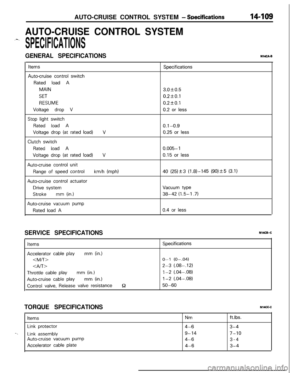
AUTO-CRUISE CONTROL SYSTEM - Snecifications14-109
AUTO-CRUISE CONTROL SYSTEM
.-4.
SPECIFICATIONS
GENERAL SPECIFICATIONSNUCA-B
ItemsSpecifications
Auto-cruise control switch
Rated load AMAIN3.OkO.5
SET0.2fO.l
RESUME0.2kO.l
Voltage drop V0.2 or less
Stop light switch
Rated load A0.1-0.9
Voltage drop (at rated load)V0.25 or less
Clutch switch
Rated load A0.005-l
Voltage drop (at rated load)V0.15 or less
Auto-cruise control unit
Range of speed controlkm/h (mph)40 (25)_+3 (1.81-145 (90)_+5 (3.1)
Auto-cruise control actuator
Drive systemVacuum type
Strokemm (in.)38-42 (1.5-I .7)
Auto-cruise vacuum pump
Rated load A0.4 or less
SERVICE SPECIFICATIONSItems
Accelerator cable playmm (in.)
4l-bThrottle
cable playmm (in.)
Auto-cruise cable playmm (in.)
Control valve, Release valve resistanceQ
Specifications
O-l (O-.04)
2-3 (.08-,121
1-2 (.04-.08)
1-2 (.04-.08)
50-60
TORQUE SPECIFICATIONSN14CGCItems
Nmftlbs.
Link protector4-63-4-.
Link assembly9-147-10
Auto-cruise vacuum pump4-63-4
Accelerator cable plate4-63-4
Page 597 of 1216
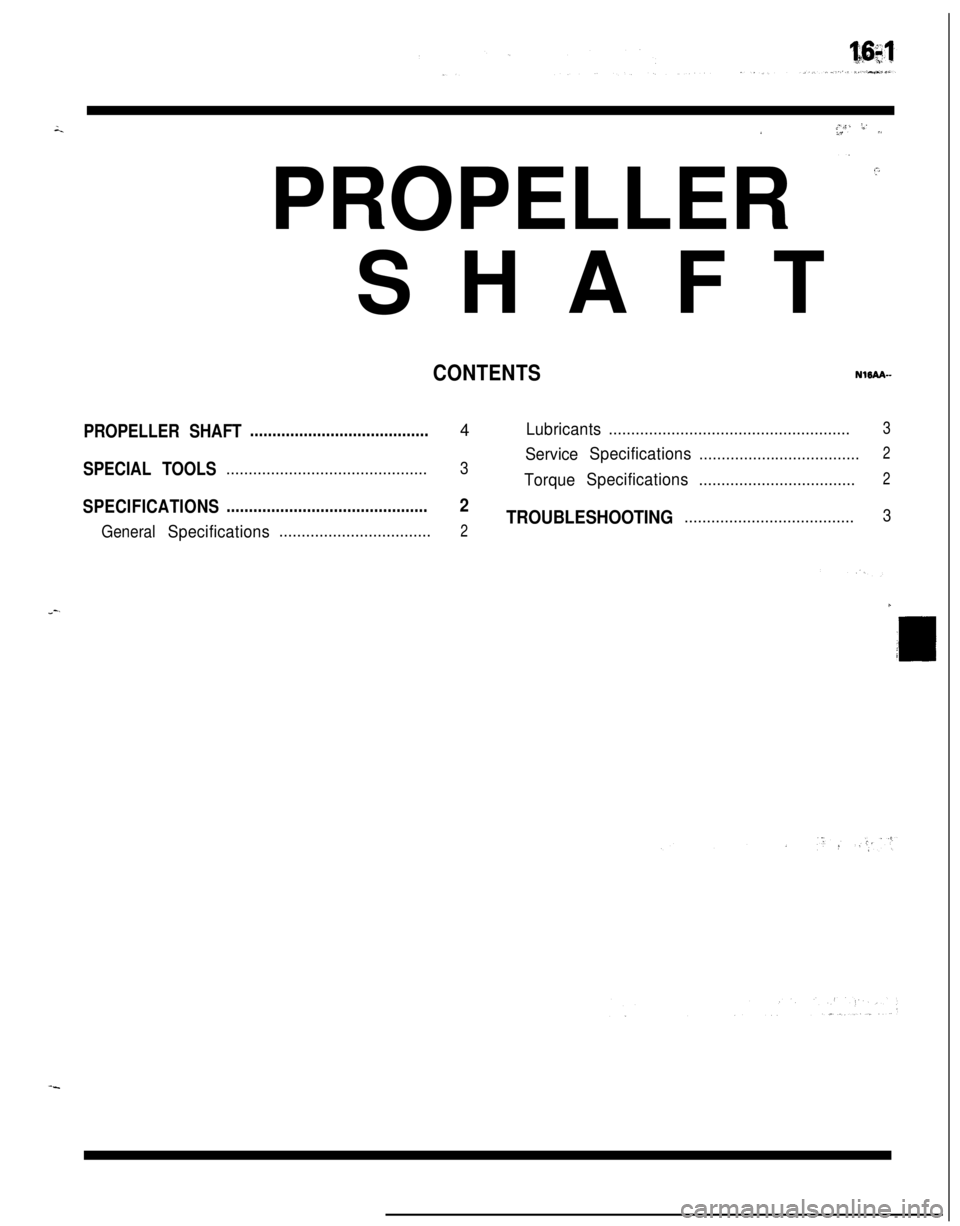
, d-a:-;._‘PROPELLER
=. ’SHAFT
CONTENTSNlBAA-
PROPELLER SHAFT........................................4Lubricants......................................................3
2
SPECIAL TOOLS3ServiceSpecifications.................................................................................
TorqueSpecifications...................................2
SPECIFICATIONS.............................................2
TROUBLESHOOTING......................................3
General
Specifications..................................21
Page 598 of 1216
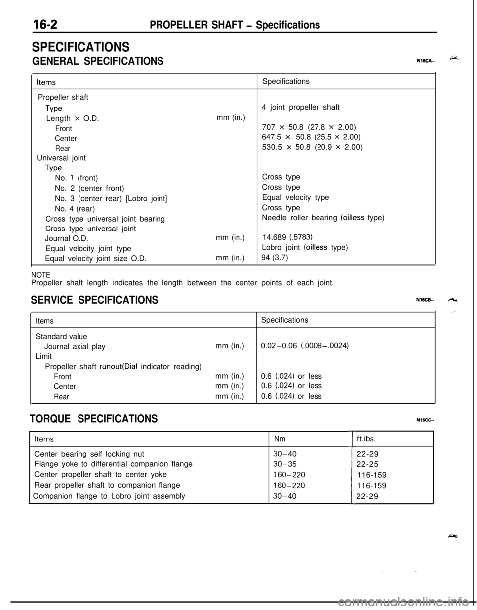
16-2PROPELLER SHAFT - Specifications
SPECIFICATIONS
GENERAL SPECIFICATIONSNWCA--
ItemsPropeller shaft
TypeLength
x O.D.
Front
Center
RearUniversal joint
TypeSpecifications
4 joint propeller shaft
mm (in.)
707
x 50.8 (27.8 x 2.00)
647.5
x. 50.8 (25.5 x 2.00)
530.5
x 50.8 (20.9 x 2.00)
No.
1 (front)
No. 2 (center front)
No. 3 (center rear) [Lobro joint]
No. 4 (rear)
Cross type universal joint bearing
Cross type universal joint
Journal O.D.
Equal velocity joint type
Equal velocity joint size O.D.mm (in.)
mm (in.)Cross type
Cross type
Equal velocity type
Cross type
Needle roller bearing
(oilless type)
14.689
(.5783)Lobro joint
(oilless type)
94 (3.7)
NOTEPropeller shaft length indicates the length between the center points of each joint.
SERVICE SPECIFICATIONSNWCB-
ItemsSpecifications
Standard value
Journal axial playmm (in.)
0.02-0.06 (.0008-.0024)
Limit
Propeller shaft
runout(Dial indicator reading)
Frontmm (in.)
0.6 (.024) or less
Centermm (in.)0.6 (.024) or less
Rearmm (in.)0.6 (.024) or less
TORQUE SPECIFICATIONSNlBCC--
ItemsNmCenter bearing self locking nut
30-40Flange yoke to differential companion flange
30-35Center propeller shaft to center yoke
160-220Rear propeller shaft to companion flange
160-220Companion flange to Lobro joint assembly
30-40tft.lbs.
22-29
22-25
116-159
116-159
22-29
Page 611 of 1216
1 pq
,s I’
:
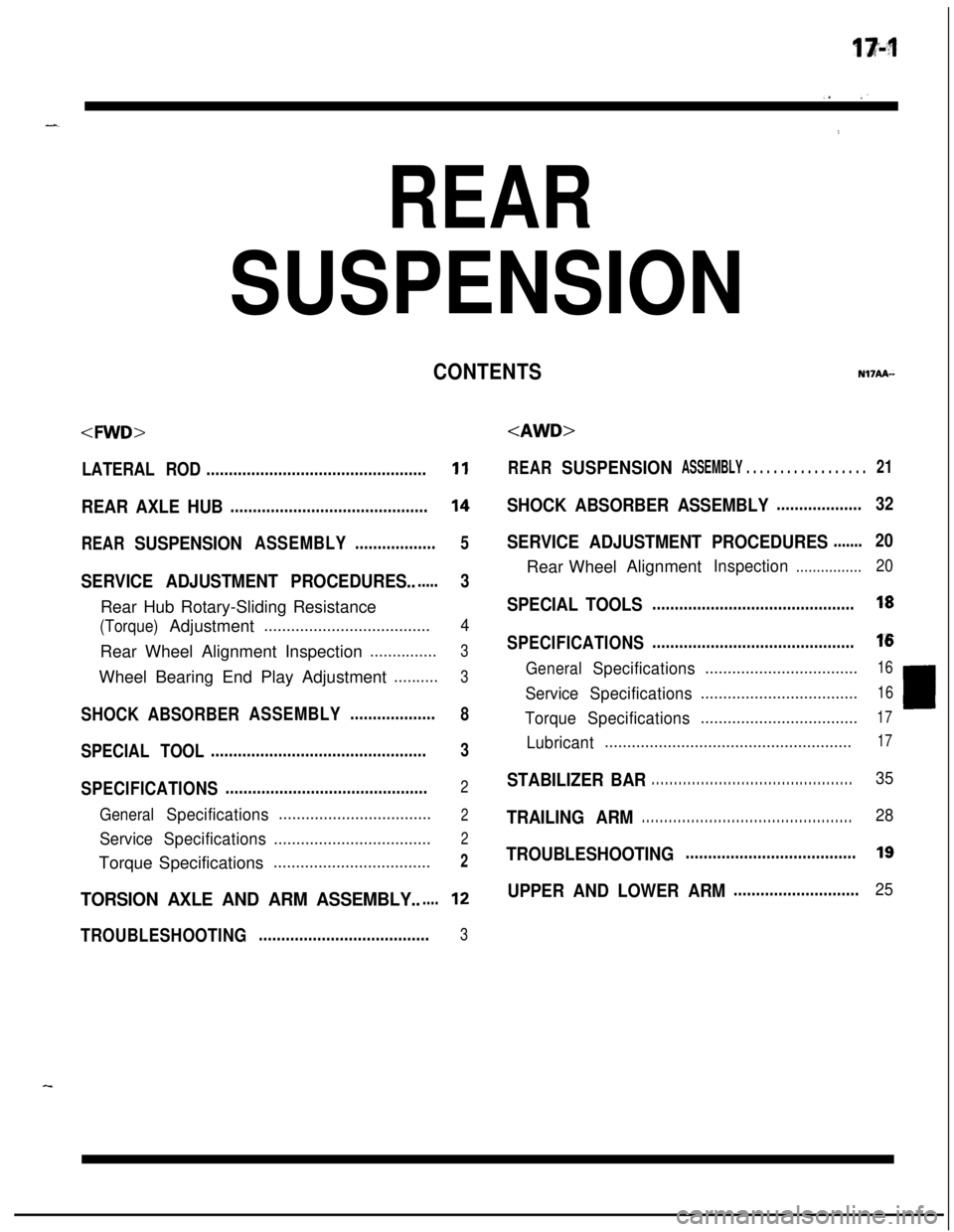
REAR
SUSPENSION
LATERAL ROD.................................................11
REAR AXLE HUB............................................14
REARSUSPENSIONASSEMBLY..................5
SERVICE ADJUSTMENT PROCEDURES.......3Rear Hub Rotary-Sliding Resistance
(Torque)Adjustment.....................................4Rear Wheel Alignment Inspection
...............3Wheel Bearing End Play Adjustment
..........3
SHOCKABSORBERASSEMBLY...................8
SPECIAL TOOL................................................3
SPECIFICATIONS.............................................2
GeneralSpecifications..................................2
ServiceSpecifications...................................2Torque Specifications
...................................2
TORSION AXLE AND ARM ASSEMBLY......12
TROUBLESHOOTING......................................3
REARSUSPENSIONASSEMBLY . . . . . . . . . . . . . . . . . .21
SHOCK ABSORBER ASSEMBLY...................32
SERVICE ADJUSTMENT PROCEDURES.......20Rear WheelAlignment
Inspection................20
SPECIAL TOOLS.............................................18
SPECIFICATIONS.............................................16
GeneralSpecifications..................................16
ServiceSpecifications...................................16LTorqueSpecifications...................................17
Lubricant.......................................................17
STABILIZER BAR. . . . . . . . . . . . . . . . . . . . . . . . . . . . . . . . . . . . . . . . . . . . .35
TRAILING ARM. . . . . . . . . . . . . . . . . . . . . . . . . . . . . . . . . . . . . . . . . . . . . . .28
TROUBLESHOOTING......................................19
UPPER AND LOWER ARM............................25
CONTENTSN17AA-
Page 612 of 1216
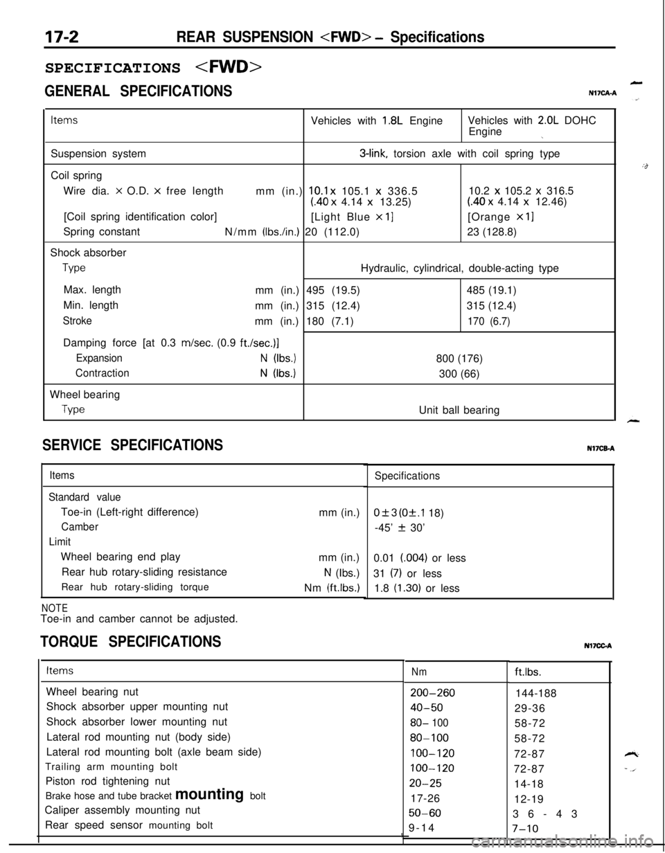
17-2REAR SUSPENSION
GENERAL SPECIFICATIONS
LN17CAA
ItemsVehicles with 1.8L EngineVehicles with 2.0L DOHC
Engine
jSuspension system
3-link, torsion axle with coil spring type
Coil spring
Wire dia.
x O.D. x free length
mm (in.) 10.1 x 105.1 x 336.510.2 x 105.2 x 316.5
(40 x 4.14 x 13.25)(40 x 4.14 x 12.46)
[Coil spring identification color]
[Light Blue
x 11[Orange x 11Spring constant
N/mm
(Ibs./in.) 20 (112.0)23 (128.8)
Shock absorber
TypeHydraulic, cylindrical, double-acting type
Max. length
mm (in.) 495 (19.5)485 (19.1)
Min. length
mm (in.) 315 (12.4)315 (12.4)
Strokemm (in.) 180 (7.1)170 (6.7)Damping force [at 0.3 m/set. (0.9
ft./set.)]
ExpansionN (Ibs.)800 (176)
ContractionN (Ibs.)300 (66)
Wheel bearing
TypeUnit ball bearing
SERVICE SPECIFICATIONS
Items
Standard valueToe-in (Left-right difference)
Camber
LimitWheel bearing end play
Rear hub rotary-sliding resistance
Rear hub rotary-sliding torque
NOTEToe-in and camber cannot be adjusted.mm (in.)
mm (in.)
N (Ibs.)
Nm
(ftlbs.)
TORQUE SPECIFICATIONS
Specifications
0+3 (Of.1 18)
-45’
f 30’
0.01 (004) or less
31
(7) or less
1.8
(1.30) or lessNI’ICB-A
ItemsNmft.lbs.
Wheel bearing nut
Shock absorber upper mounting nut
Shock absorber lower mounting nut
Lateral rod mounting nut (body side)
Lateral rod mounting bolt (axle beam side)
Trailing arm mounting bolt
Piston rod tightening nut
Brake hose and tube bracket mounting bolt
Caliper assembly mounting nut
Rear speed sensor mounting bolt
200-260
40-50
80- 100
80-100
100-120
100-120
20-2517-26
50-609-14144-188
29-36
58-72
58-72
72-87
72-87
14-18
12-19
36-43
I7-10
Nl7CGA
Page 627 of 1216
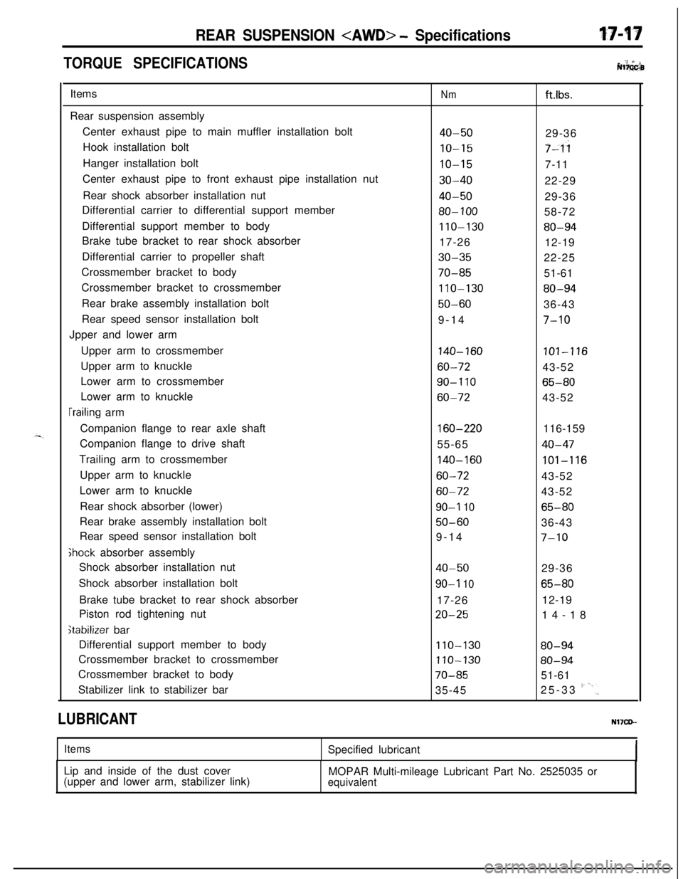
REAR SUSPENSION
TORQUE SPECIFICATIONS. ‘2 +’ iiNl?GGbItems
Rear suspension assembly
Center exhaust pipe to main muffler installation bolt
Hook installation bolt
Hanger installation bolt
Center exhaust pipe to front exhaust pipe installation nut
Rear shock absorber installation nut
Differential carrier to differential support member
Differential support member to body
Brake tube bracket to rear shock absorber
Differential carrier to propeller shaft
Crossmember bracket to body
Crossmember bracket to crossmember
Rear brake assembly installation bolt
Rear speed sensor installation bolt
Jpper and lower arm
Upper arm to crossmember
Upper arm to knuckle
Lower arm to crossmember
Lower arm to knuckle
[railing arm
Companion flange to rear axle shaft
Companion flange to drive shaft
Trailing arm to crossmember
Upper arm to knuckle
Lower arm to knuckle
Rear shock absorber (lower)
Rear brake assembly installation bolt
Rear speed sensor installation bolt
Ghock absorber assembly
Shock absorber installation nut
Shock absorber installation bolt
Brake tube bracket to rear shock absorber
Piston rod tightening nut
stabilizer bar
Differential support member to body
Crossmember bracket to crossmember
Crossmember bracket to body
Stabilizer link to stabilizer bar
Nmft.lbs.
40-5029-36
IO-157-ii
IO-157-11
30-4022-29
40-5029-36
80-10058-72
110-13080-9417-26
12-19
30-3522-25
70-8551-61
110-13080-94
50-6036-43
9-14
7-10
140-160101-116
60-7243-52
90-I 1065-80
60-7243-52
160-220116-159
55-65
40-47
140-160101-116
60-7243-52
60-7243-52
90-I 1065-80
50-6036-43
9-14
7-10
40-5029-36
90-l 1065-8017-2612-19
20-2514-18
110-13080-94
110-13080-94
70-8551-61
35-4525-33
I'-'.
LUBRICANTNl’ICD-
ItemsSpecified lubricant
Lip and inside of the dust cover
(upper and lower arm, stabilizer link)MOPAR Multi-mileage Lubricant Part No. 2525035 or
equivalent