torque specification MITSUBISHI ECLIPSE 1991 Workshop Manual
[x] Cancel search | Manufacturer: MITSUBISHI, Model Year: 1991, Model line: ECLIPSE, Model: MITSUBISHI ECLIPSE 1991Pages: 1216, PDF Size: 67.42 MB
Page 853 of 1216
AUTOMATIC TRANSAXLE - Specifications
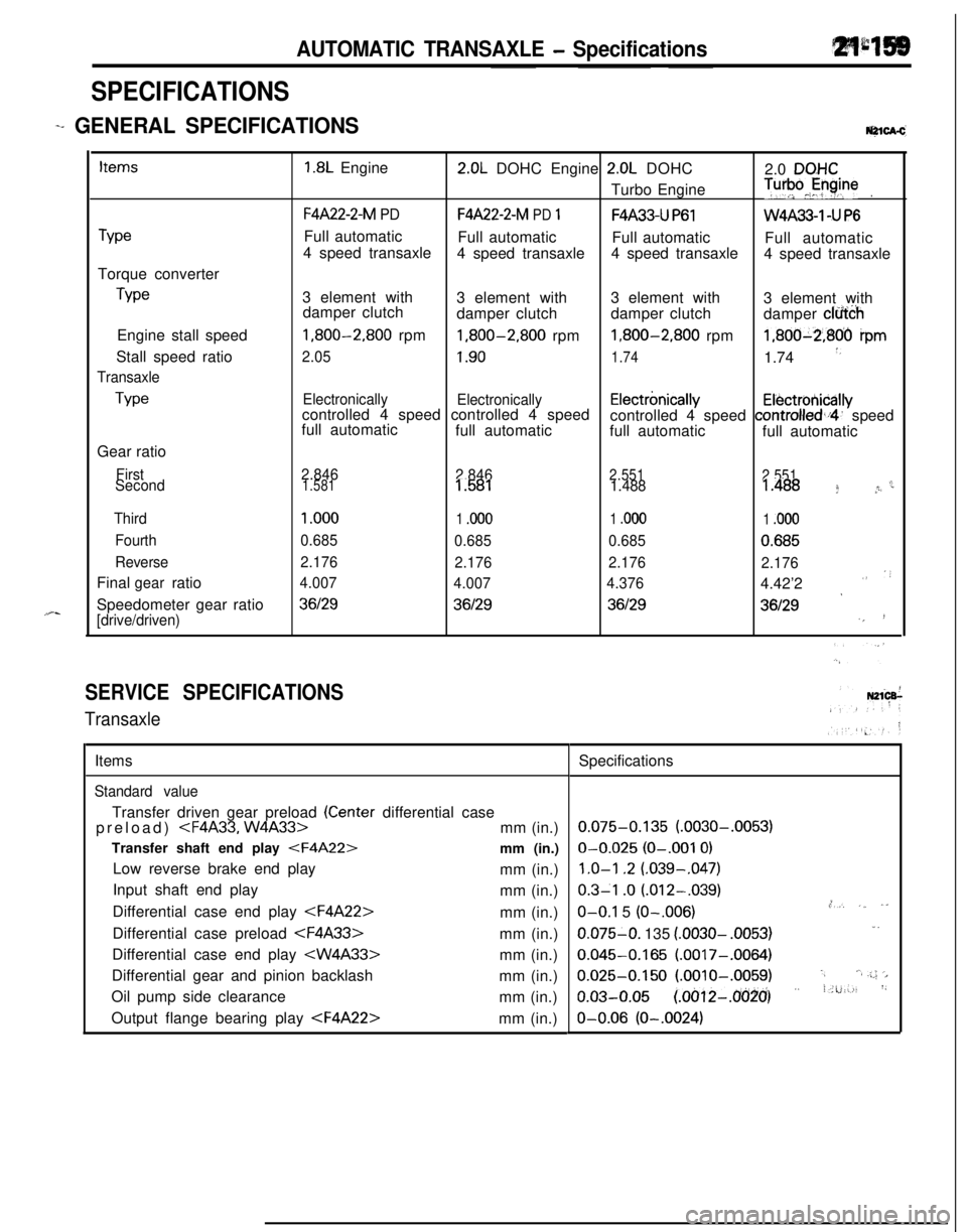
SPECIFICATIONS
-+ GENERAL [email protected]
TypeTorque converter
TypeEngine stall speed
Stall speed ratio
Transaxle
TypeGear ratio
First
Second
Third
Fourth
ReverseFinal ratio
gearSpeedometer gear ratio
[drive/driven)
1.8L Engine2.0L DOHC Engine 2.0L DOHC
2.0 DQHCTurbo Engine
T”‘pJyine.
F4A22-2-M PDF4A22-2-M PD 1F4A33-U P61W4A33-1 -U P6Full automatic
Full automatic
Full automatic
Full automatic
4 speed transaxle
4 speed transaxle4 speed transaxle
4 speed transaxle
3 element with
3 element with3 element with
3 element with
damper clutch
damper clutchdamper clutch
damper clfi&h
1,800-2,800 rpm1,800-2,800 rpm1,800-2,800 rpm1,800-2,806 ipm
2.051.901.741.74 *,
Electronically
Electronicallycontrolled 4 speed controlled 4 speedElectrbnicallyElectrotiicallyfull automaticcontrolled 4 speed controlled,i4’ speed
full automatic
full automatic
full automatic
2.846
2.8462.551
2.551c1.5811.5811.4881.488 f *r
1 .ooo
1 .ooo1 .ooo1 .ooo
0.685
0.6850.6850.685
2.176
2.1762.176
2.176
4.007
4.0074.3764.42’2
””
*36129361293612936129‘,!
SERVICE SPECIFICATIONS
TransaxleItems
Standard valueTransfer driven gear preload
(Center differential case
preload)
Transfer shaft end play
Low reverse brake end play
mm (in.)
Input shaft end play
mm (in.)
Differential case end play
Differential case preload
Differential case end play
Differential gear and pinion backlash
mm (in.)
Oil pump side clearance
mm (in.)
Output flange bearing play
0.075-0.135 (.0030-.0053)O-0.025
(O-.001 0)
1.0-l .2 (.039-,047)
0.3-l .o (.012-.039).,O-O.1 5 (O-.006),*, ,_ ,”0.075-O. 135
(.0030- .0053)1.
0.045-0.165 (.0017-.0064)
0.025-0.150 (.OOlO-.0059).,‘.a .;.; ‘>
o.03-o.05 (~oo12-~o(j~o’) ” i.u:-., ‘~O-0.06
(O-.0024)
Page 854 of 1216
21-160AUTOMATIC TRANSAXLE - Specifidons
ItemsOutput flange bearing end play
Front clutch end play
End clutch end play
Front clutch end play
Rear clutch end play
End clutch end play
Transfer idler gear preload
Front output shaft end play
Transfer
Driven bevel gear starting torque
Bevel gear backlashNm
(ft.lbs.)Nm
(ft.lbs.)mm (in.)
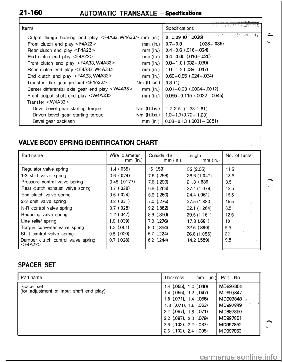
IALVE BODY SPRING IDENTIFICATION CHARTPart name
Regulator valve spring
l-2 shift valve spring
Pressure control valve spring
Rear clutch exhaust valve spring
End clutch valve spring
2-3 shift valve spring
N-R control valve spring
Reducing valve spring
Line relief spring
Torque converter valve spring
Shift control valve spring
FFyl;;;lutch control valve spring
SPACER SETWire diameter
mm (in.)
1.4 (055)
0.6 (024)
0.45 (0177)
0.7 (028)
0.6
(.024)0.8
(.031)0.7 (028)
1.2 (047)
1.0 l.039)
1.3 (051)
0.5 (020)
0.7
(.028)Outside dia.
mm (in.)
15i.59)
7.6
t.299)
7.6(.299)
6.8(.268)
6.6(260)
7.0(276)
9.2(.362)
8.9(350)
7.0(276)
9.0(.354)
5.7(224)
6.2(.244)
IPart name
Spacer set
(for adjustment of input shaft end play)Specifications
o-0.09 (d-.0035); . ,i f 1, ,i’.” :,li
0.7-0.9 (.028-.035)
0.4-0.6 (.016-.024)
0.4-0.65 (.016-.026)
0.8-I .O (.032-.039)
1.0-I .2 (.039-.047)
0.60-0.85 (.024-.034)
0.8
(1)
0.01-0.03 (.0004-.0012)
0.055-0.115 (.0022-.0045)
1.7-2.5 (1.23-1.81)
1.0-I .7 (0.72- 1.23)
0.08-0.13 (.0031-.0051)
Lengthmm (in.)
52 (2.05)
26.6 (1.047)
21.3
(.839)27.4 (1.079)
24.4
(.961)27.5 (1.883)
32.1 (1.264)
29.5 (1.161)
17.3
(.681)22.6
i.890)26.8 (1.055)
14.2
(.559)No. of turns
11.5
13.5
8.5
12.5
15.5
15.5
‘4
8.5
’-*12.5
10
9.5
’22
9.5I
Thicknessmm (in.) Part No. “’
1.4(055).1.0l.040)MD997854
1.4(.055),
1.2(047)MD997847
’1.8(.071),
1.4l.055)MD997848::!1.8
(.071), 1.6 (.063)fQlD997849 ” .’
2.2(.087),
1.8(.071)MD997850
2.2(.087),2.0(.079)MD997851h2.6(.102),2.2(.087)MD997852“-2.6(.102),2.4i.095)M D997853
Page 860 of 1216
21-166AUTOMATIC TRANSAXLE - SDecifications
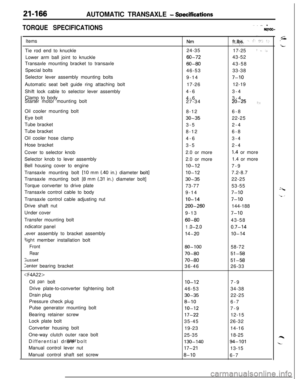
TORQUE SPECIFICATIONS,. _ ,,,_ .Nglcc-
ItemsTie rod end to knuckle
Lower arm ball joint to knuckle
Transaxle mounting bracket to transaxle
Special bolts
Selector lever assembly mounting bolts
Automatic seat belt guide ring attaching bolt
Shift lock cable to selector lever assembly
Clamp to body
Starter motor mounting bolt
Oil cooler mounting bolt
Eye bolt
Tube bracket
Tube bracket
Oil cooler hose clamp
Hose bracket
Cover to selector knob
Selector knob to lever assembly
Bell housing cover to engine
Transaxle mounting bolt
[lo mm l.40 in.) diameter bolt]Transaxle mounting bolt
[8 mm I.31 in.) diameter bolt]
Torque converter to drive plate
Transaxle control cable to body
Transaxle control cable adjusting nut
Drive shaft nut
Under cover
Transfer mounting boltndicator panel-ever assembly to bracket assembly
3ight member installation bolt
Front
Rear
;usset
Zenter bearing bracket
:l=4A22>Oil bolt
panDrive plate-to-converter tightening bolt
Drain plug
Pressure check plug
Pulse generator mounting bolt
Bearing retainer screw
Lock plate bolt
Converter housing bolt
One-way clutch outer race bolt
Differential drive bolt
gearManual control lever nut
Manual control shaft set screw
Nm24-35
60-72
60-8046-53
9-14
17-26
4-6
4-6
27-34
8-12
30-353-5
8-12
4-6
3-5
2.0 or more
2.0 or more
10-12
10-12
30-3573-77
9-14
IO-14
200-2609-13
60-80
1 .o-2.0
14-20
80- 100
70-80
70-8036-46
10-1246-53
30-35
8-10
IO-12
17-2235-45
19-23
25-35
130-14017-21
8-10
-.
ft*lgk+ ‘. St. :“.. (1.17-25
I ~. ‘,43-52
43-58
33-38
7-1012-19
3-4
3-4
20-25i::6-8
22-25
2-4
6-8
3-4
2-4
1..4 or more
1.4 or more
7-9
7.2-8.7
22-25
53-55
7-10
7-10144-188
7-1043-58
0.7-14
10-1458-72
51-58
51-5826-33
7-9
34-38
22-25
6-7
7-9
12-15
26-32
14-16
18-25
94-10113-15
6-7
Page 896 of 1216
21-202AUTOMATIC TRANSAXLE - Troubleshooting
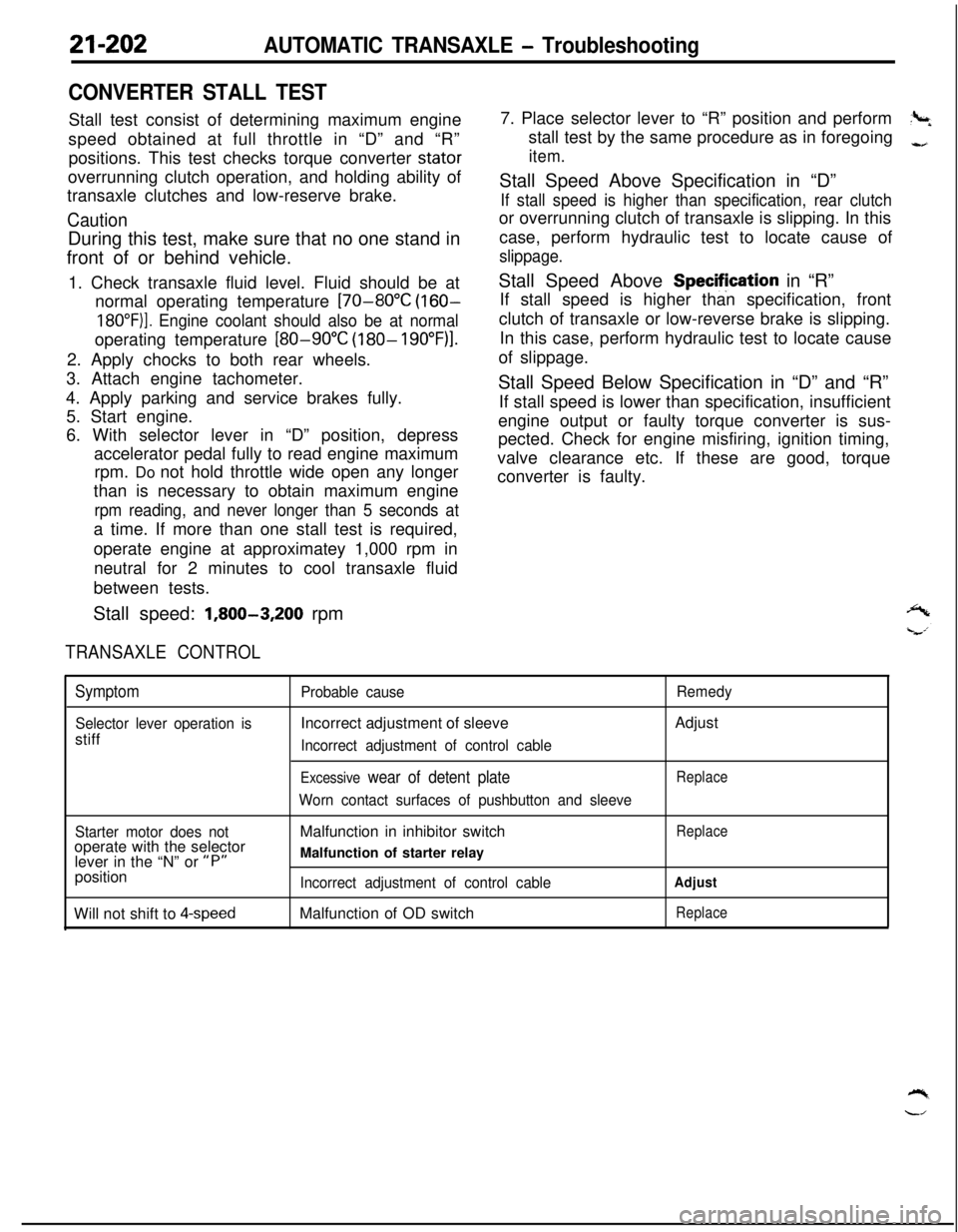
CONVERTER STALL TESTStall test consist of determining maximum engine
speed obtained at full throttle in “D” and “R”
positions. This test checks torque converter stator
overrunning clutch operation, and holding ability of
transaxle clutches and low-reserve brake.
CautionDuring this test, make sure that no one stand in
front of or behind vehicle.
1. Check transaxle fluid level. Fluid should be at
normal operating temperature
[70-80°C (160-
18O”F)]. Engine coolant should also be at normaloperating temperature
[80-90°C (180- 19O”F)l.2. Apply chocks to both rear wheels.
3. Attach engine tachometer.
4. Apply parking and service brakes fully.
5. Start engine.
6. With selector lever in “D” position, depress
accelerator pedal fully to read engine maximum
rpm. Do not hold throttle wide open any longer
than is necessary to obtain maximum engine
rpm reading, and never longer than 5 seconds ata time. If more than one stall test is required,
operate engine at approximatey 1,000 rpm in
neutral for 2 minutes to cool transaxle fluid
between tests.
Stall speed:
1,800-3,200 rpm
TRANSAXLE CONTROL7. Place selector lever to “R” position and perform
?+stall test by the same procedure as in foregoing
-,
item.Stall Speed Above Specification in “D”
If stall speed is higher than specification, rear clutchor overrunning clutch of transaxle is slipping. In this
case, perform hydraulic test to locate cause of
slippage.Stall Speed Above Specifjcation in “R”
If stall speed is higher than specification, front
clutch of transaxle or low-reverse brake is slipping.
In this case, perform hydraulic test to locate cause
of slippage.
Stall Speed Below Specification in “D” and “R”
If stall speed is lower than specification, insufficient
engine output or faulty torque converter is sus-
pected. Check for engine misfiring, ignition timing,
valve clearance etc. If these are good, torque
converter is faulty.
Symptom
Selector lever operation isstiff
Probable causeIncorrect adjustment of sleeve
Incorrect adjustment of control cable
Excessive wear of detent plate
Worn contact surfaces of pushbutton and sleeveRemedyAdjust
Replace
Starter motor does notoperate with the selector
lever in the “N” or
“P”position
Will not shift to
4-speedMalfunction in inhibitor switch
Malfunction of starter relay
Incorrect adjustment of control cableMalfunction of OD switch
Replace
Adjust
Replace
Page 1039 of 1216
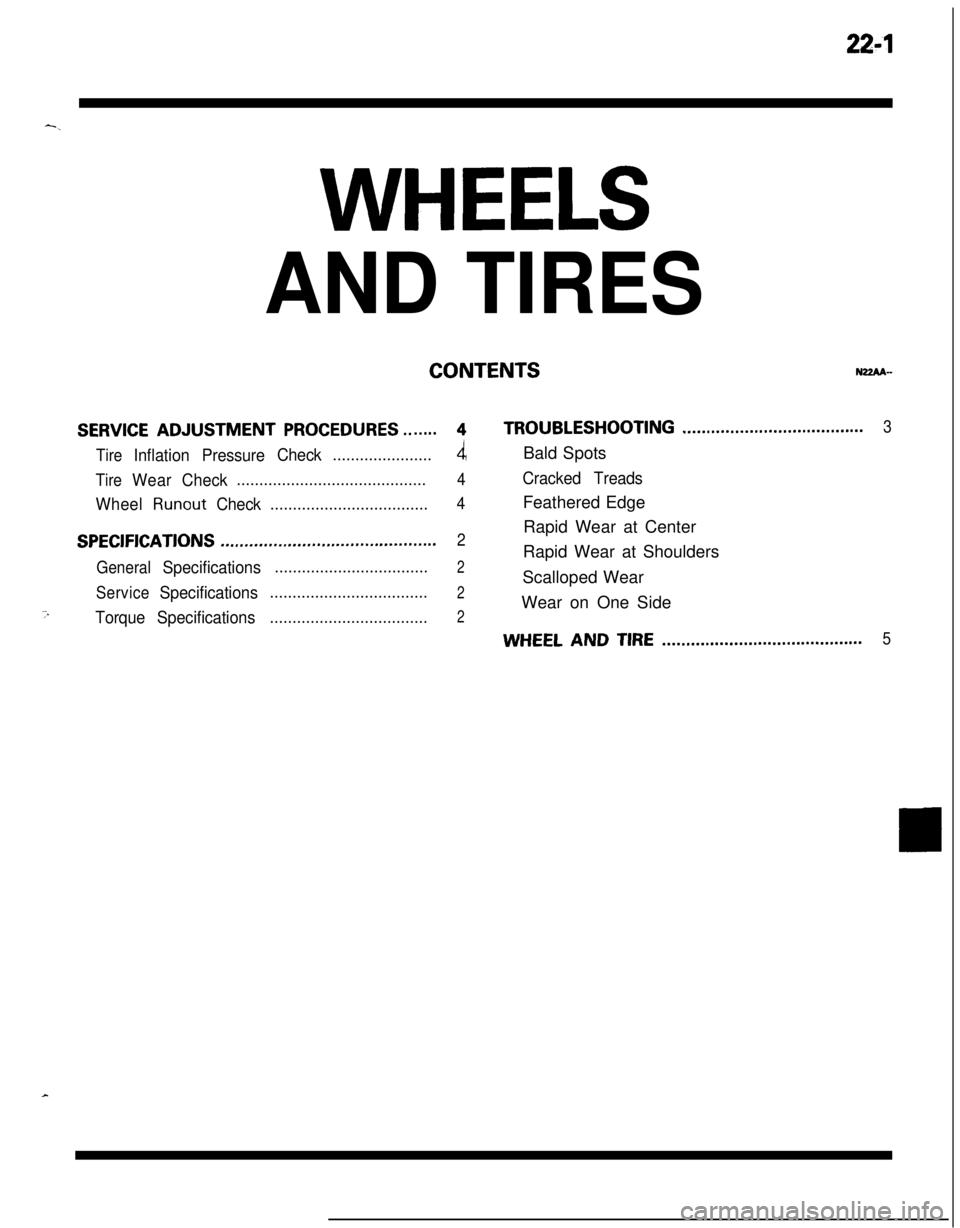
22-l-.
WHEELS
AND TIRES
CONTENTSNZZAA-
SERVICE ADJUSTMENT PROCEDURES.......4TROUBLESHOOTING......................................3
Tire
InflationPressureCheck......................4Bald Spots
TireWearCheck..........................................4Cracked Treads
Wheel
RunoutCheck...................................4Feathered Edge
SPECIFICATIONSRapid Wear at Center.............................................2
General
Specifications..................................2Rapid Wear at Shoulders
ServiceSpecificationsScalloped Wear...................................2Wear on One Side
7TorqueSpecifications...................................2
WHEEL AND TIRE..........................................5
Page 1040 of 1216
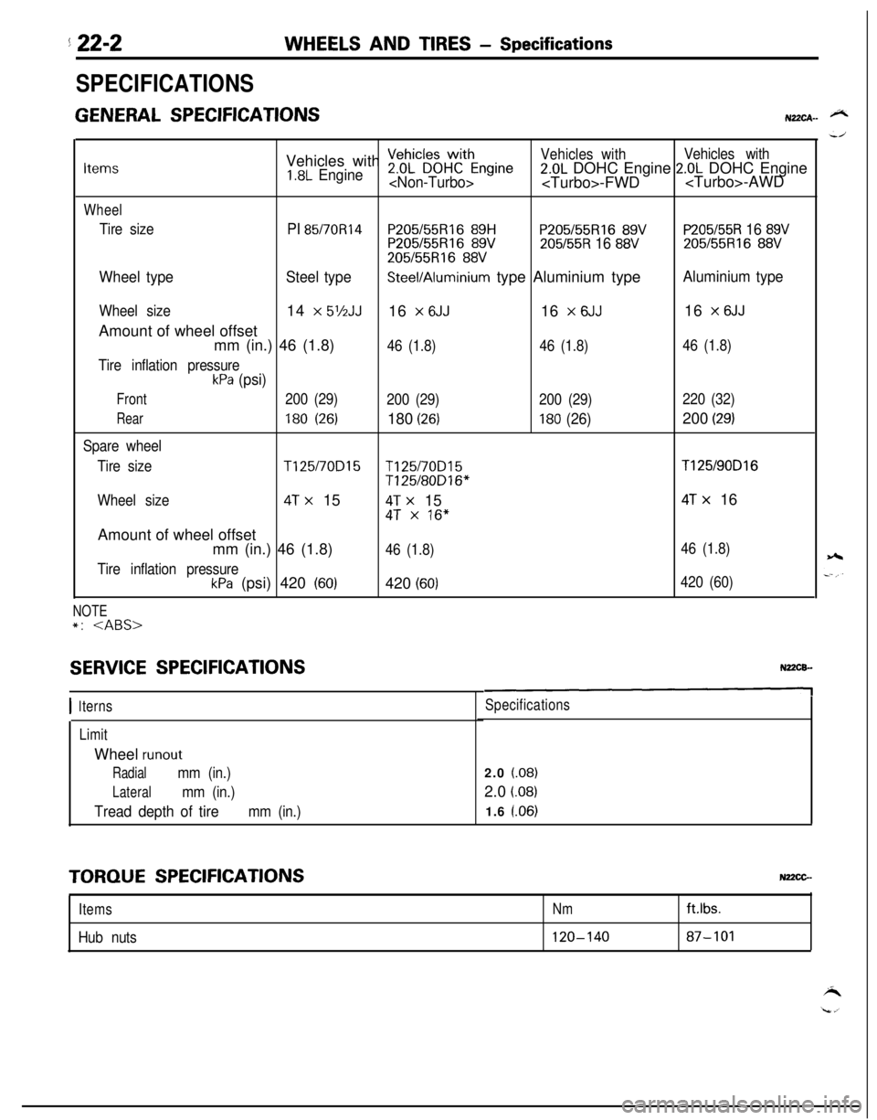
5 22-2WHEELS AND TIRES - Specifications
SPECIFICATIONS
GENERAL SPECIFICATIONSN22CA- @NVehicles with
~eDhL”~~HWCthEngineVehicles withVehicles withItems1.8L Engine2.0L DOHC Engine 2.0L DOHC Engine
Wheel
Tire sizePI 85/70R14P205155Rl6 89HP205/55R16 89VP205/55R 16 89VP205155R16 89V205/55R 16 88V205/55R16 88V
205/55R16 88V
Wheel typeSteel typeSteel/Aluminium type Aluminium typeAluminium type
Wheel size14 x 5’/2JJ16 x 6JJ16 x 6JJ16 x 6JJAmount of wheel offset
mm (in.) 46 (1.8)
46 (1.8)46 (1.8)46 (1.8)
Tire inflation pressure
kPa (psi)
Front200 (29)
200 (29)200 (29)220 (32)
Rear180 (26)180 (26)180 (26)200 (29)
Spare wheel
Tire size
T125/70D15T125/70D15T125/90D16
T125/80D16*
Wheel size
4T x 154T x 154T x 16
4T x 16”Amount of wheel offset
mm (in.) 46 (1.8)
46 (1.8)46 (1.8)
Tire inflation pressure
kPa (psi) 420 (60)420 (60)420 (60)
NOTE*:
SERVICE SPECIFICATIONS
I 1terns
LimitWheel
runout
Radialmm (in.)
Lateralmm (in.)
Tread depth of tiremm (in.)
Specifications2.0
(.08)2.0
i.08)1.6 l.06)
TORQUE SPECIFICATIONSNz2cG-
ItemsNm
Hub nuts120-140ftlbs.87-101
Page 1045 of 1216
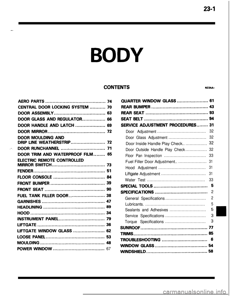
23-lBODY
CONTENTSN23Ak-
AERO PARTS..........................................74
CENTRAL DOOR LOCKING SYSTEM...........70
DOOR ASSEMBLY....................................63
DOOR GLASS AND REGULATOR................66
DOORHANDLEANDLATCH.....................69
DOOR MIRROR........................................72
DOOR MOULDING AND
DRIP LINE WEATHERSTRIP........................72
....DOOR RUNCHANNEL...............................71
DOOR TRIM AND WATERPROOF FILM........65
ELECTRIC REMOTE CONTROLLED
MIRROR SWITCH.....................................73
FENDER..................................................51
FLOOR CONSOLE....................................84
FRONT BUMPER......................................39
FRONT SEAT..........................................90
FUEL TANKFILLERDOOR.........................38
GARNISHES............................................47
HEADLINING...........................................89
HOOD....................................................34
INSTRUMENT PANEL................................79
LIFTGATE...............................................36
LIFTGATE WINDOWGLASS......................62
LOOSE PANEL.........................................53
MOULDING.............................................48
POWER WINDOW....................................67
QUARTERWINDOWGLASS......................61
REAR BUMPER........................................43
REAR SEAT............................................93
SEAT BELT.............................................94
SERVICE ADJUSTMENT PROCEDURES........31
Door Adjustment....................................32
Door Glass Adjustment............................32Door Inside Handle Play Check..................
32
Door Outside Handle Play Check................32
Floor PanInspection...............................
33Fuel Filler Door Adjustment.......................
31
Hood Adjustment...................................31
Liftgate Adjustment.................................31
Water Test...........................................33
SPECIAL TOOLS......................................5
SPECIFICATIONS.....................................2
General Specifications..............................
2
Lubricants.............................................5
Sealants and Adhesives...........................5
Service Specifications..............................3
Torque Specifications..............................3
SUNROOF...............................................77TRIMS
....................................................85
TROUBLESHOOTING................................6WINDOW
GLASS.....................................54
WINDSHIELD...........................................58
Page 1047 of 1216
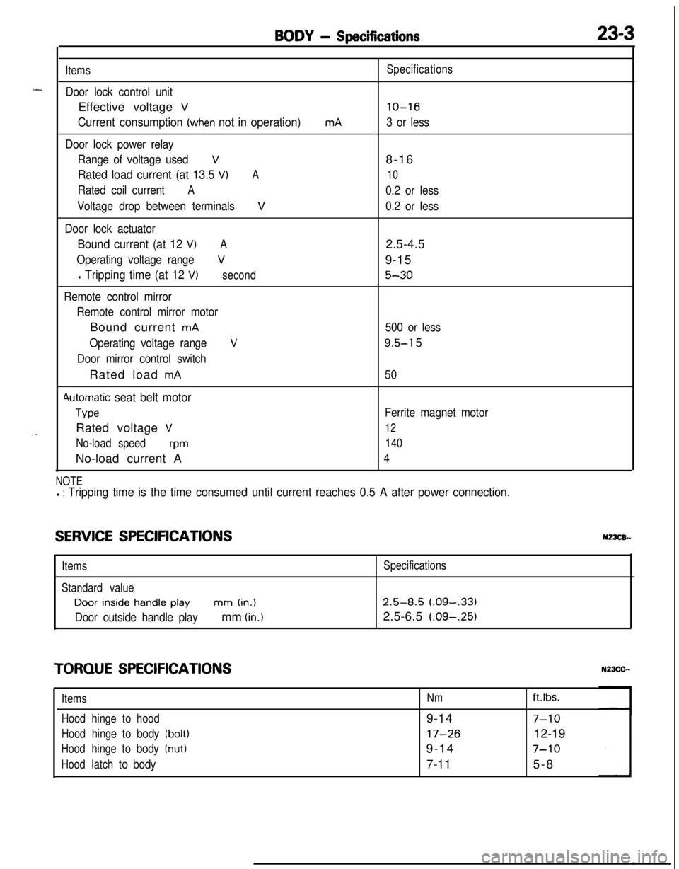
BODY - Specifications23-3
Items
Door lock control unitEffective voltage
V
Current consumption (when not in operation)
Door lock power relay
Range of voltage used
V
Rated load current (at 13.5 VIA
Rated coil currentA
Voltage drop between terminalsV
Door lock actuator
Bound current (at 12 VIA
Operating voltage rangeV
l Tripping time (at 12 V)second
Remote control mirror
Remote control mirror motorBound current
mA
Operating voltage range
V
Door mirror control switchRated load
mA
4utomatic seat belt motor
TypeRated voltage
V
No-load speedwmNo-load current A
mASpecifications
lo-16
3 or less8-16
10
0.2 or less
0.2 or less2.5-4.5
9-15
5-30
500 or less
9.5-l 5
50
Ferrite magnet motor
12
140
4
NOTEl : Tripping time is the time consumed until current reaches 0.5 A after power connection.
SERVICE SPECIFICATIONSN23CB--
ItemsSpecifications
Standard valueDoor
inside handle playmm (in.)2.5-8.5 (.09-,331
Door outside handle playmm (in.)2.5-6.5 (.09-.25)
TORQUE SPECIFICATIONS
ItemsNmft.lbs.
Hoodhingetohood9-14
7-10
Hoodhingetobody(bolt)17-2612-19
Hoodhingetobody(nut)9-147-10
Hoodlatchtobody7-115-8
Page 1145 of 1216
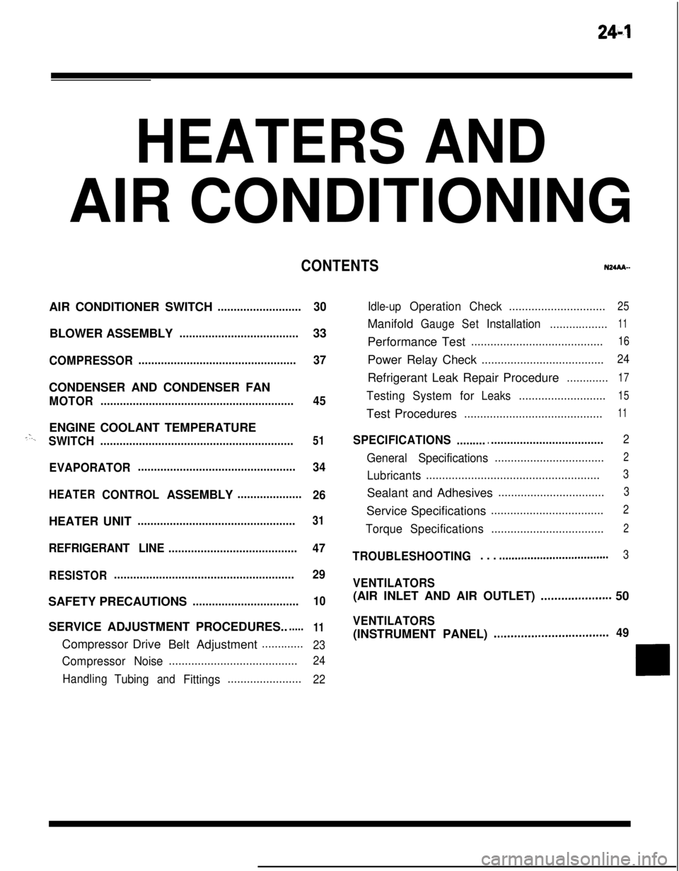
24-l
HEATERS ANDAIR CONDITIONING
CONTENTSN24M--AIR CONDITIONER SWITCH
..........................30BLOWER ASSEMBLY
.....................................33
COMPRESSOR.................................................37CONDENSER AND CONDENSER FAN
MOTOR............................................................45ENGINE COOLANT TEMPERATURE
-‘-.,SWITCH............................................................51
EVAPORATOR.................................................
34
HEATERCONTROLASSEMBLY....................
26HEATER UNIT
.................................................31
REFRIGERANTLINE........................................47
RESISTOR........................................................29SAFETY PRECAUTIONS
.................................10SERVICE ADJUSTMENT PROCEDURES..
.....11Compressor Drive
Belt Adjustment
.............
23
CompressorNoise........................................24
Handling
TubingandFittings.......................22Idle-up
OperationCheck..............................25Manifold
GaugeSetInstallation..................11Performance Test
.........................................16Power Relay Check
......................................24Refrigerant Leak Repair Procedure
.............17
TestingSystemforLeaks...........................15Test Procedures
...........................................11
SPECIFICATIONS.............................................2
General Specifications..................................2
Lubricants......................................................3Sealant and Adhesives
.................................3Service Specifications
...................................2
TorqueSpecifications...................................2
TROUBLESHOOTING. . . ..a................................3
VENTILATORS(AIR INLET AND AIR OUTLET)
..,....s............. 50
VENTILATORS(INSTRUMENT PANEL)
..,...................*...........49
Page 1146 of 1216
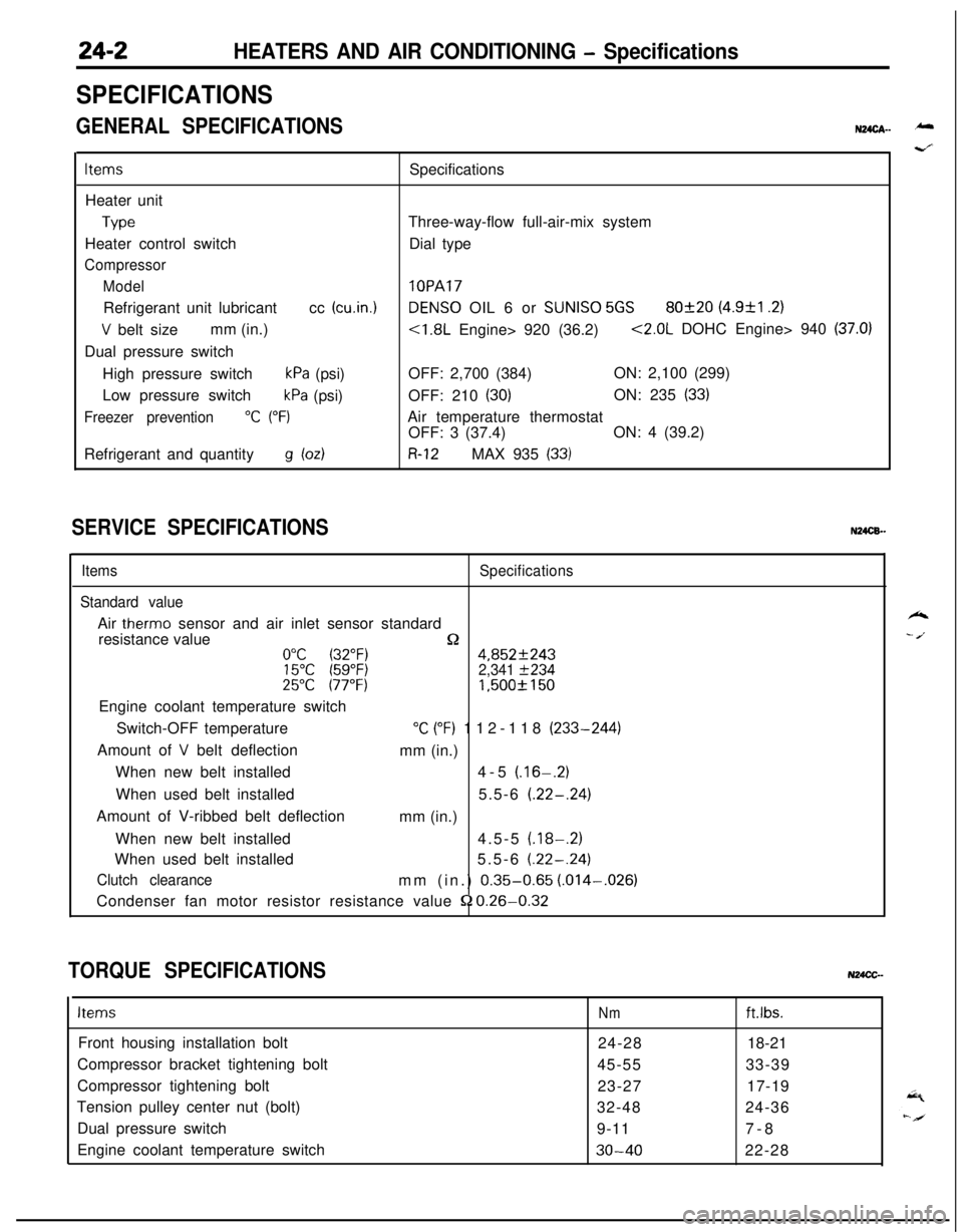
24-2HEATERS AND AIR CONDITIONING - Specifications
SPECIFICATIONS
GENERAL SPECIFICATIONSN24cA- -
ItemsSpecifications
Heater unit
TypeThree-way-flow full-air-mix system
Heater control switchDial type
Compressor
Model
lOPARefrigerant unit lubricantcc
(cu.in.1DENS0 OIL 6 or SUNISO 5GS80f20 (4.9&l .2)
V belt sizemm (in.)<1.8L Engine> 920 (36.2)<2.0L DOHC Engine> 940 (37.0)Dual pressure switch
High pressure switch
kPa (psi)OFF: 2,700 (384)ON: 2,100 (299)
Low pressure switch
kPa (psi)OFF: 210 (30)ON: 235 (33)
Freezer prevention“C (“F)Air temperature thermostat
OFF: 3 (37.4)ON: 4 (39.2)
Refrigerant and quantity
g bdR-12MAX 935 (33)
SERVICE SPECIFICATIONSN24CB.-
ItemsSpecifications
Standard valueAir
therm0 sensor and air inlet sensor standard
resistance value
n0°C (32°F)4,852f24315°C (59°F)2,341 f23425°C 177°F)1,500f 150Engine coolant temperature switch
Switch-OFF temperature
“C (“F) 112-118 (233-244)
Amount of
V belt deflection
mm (in.)
When new belt installed4-5
(.16-.2)When used belt installed5.5-6
(.22-.24)Amount of V-ribbed belt deflection
mm (in.)
When new belt installed4.5-5
(.18-.2)When used belt installed5.5-6
(.22-.24)
Clutch clearancemm (in.) 0.35-0.65 (.014-,026)
Condenser fan motor resistor resistance value
52 0.26-0.32
TORQUE SPECIFICATIONSN24CC-
ItemsNmft.lbs.Front housing installation bolt
24-2818-21
Compressor bracket tightening bolt
45-5533-39
Compressor tightening bolt
23-2717-19
Tension pulley center nut (bolt)
32-4824-36
Dual pressure switch
9-117-8
Engine coolant temperature switch
30-4022-28
k
- /.