key MITSUBISHI ECLIPSE 1991 Owner's Manual
[x] Cancel search | Manufacturer: MITSUBISHI, Model Year: 1991, Model line: ECLIPSE, Model: MITSUBISHI ECLIPSE 1991Pages: 1216, PDF Size: 67.42 MB
Page 665 of 1216
STEERING - Steering Wheel and Shaft
1610778
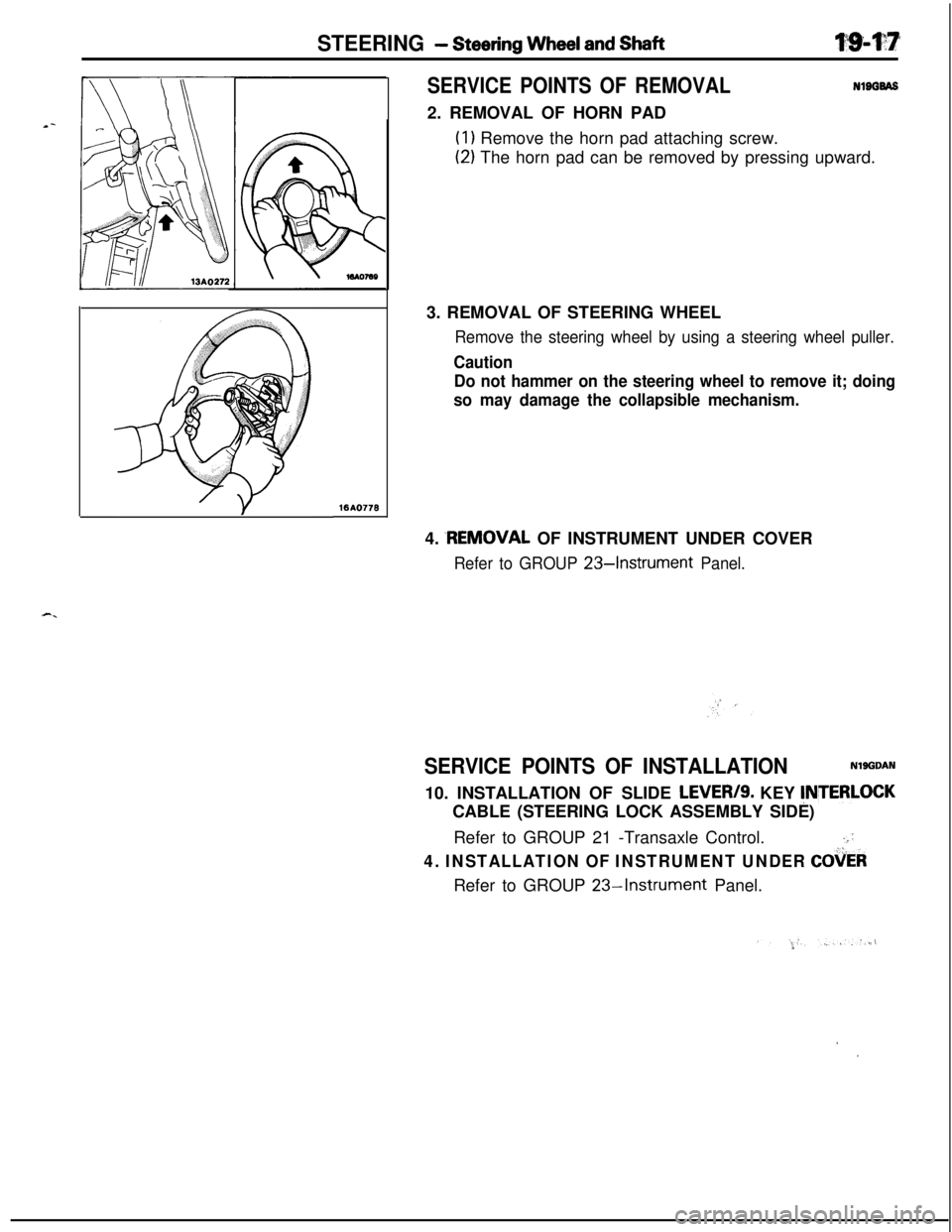
SERVICE POINTS OF REMOVALNlBGBAS2. REMOVAL OF HORN PAD
(1) Remove the horn pad attaching screw.
(2) The horn pad can be removed by pressing upward.
3. REMOVAL OF STEERING WHEEL
Remove the steering wheel by using a steering wheel puller.
Caution
Do not hammer on the steering wheel to remove it; doing
so may damage the collapsible mechanism.4.
.REMOVAL OF INSTRUMENT UNDER COVER
Refer to GROUP 234nstrument Panel.
SERVICE POINTS OF INSTALLATIONNlgGDAN10. INSTALLATION OF SLIDE
LEVER/S. KEY !NTERLOCKCABLE (STEERING LOCK ASSEMBLY SIDE)
Refer to GROUP 21 -Transaxle Control.
.::
4. INSTALLATION OF INSTRUMENT UNDER COiiERRefer to GROUP
23-Instrument Panel.
,I
Page 695 of 1216
TRANSAXLE ’
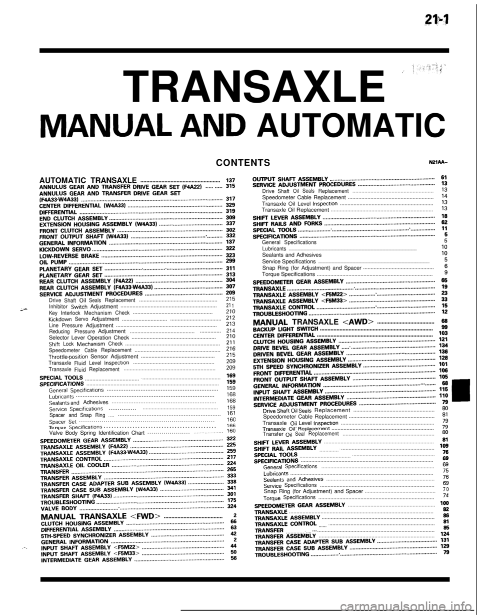
MANUAL AND AUTOMATICCONTENTS
;-AUTOMATICTRANSAXLE
.....................................................137ANNULUS GEAR AND TRANSFER DRIVE GEAR SET (F4A22)..........315ANNULUS GEAR AND TRANSFER DRIVE GEAR SET(F4A33.W4A33)...........................................................................................317CENTERDIFFERENTIAL(W4A33).............................................................329DIFFERENTIAL............................................................................................319ENDCLUTCHASSEMBLY.........................................................................309EXTENSIONHOUSINGASSEMBLY(W4A33).........................................337FRONTCLUTCHASSEMBLY....................................................................302FRONTOUTPUTSHAFT(W4A33)...........................................................332GENERALINFORMATION.........................................................................137KICKDOWNSERVO....................................................................................322LOW-REVERSEBRAKE..............................................................................323OILPUMP...................................................................................................299PLANETARYGEARSET............................................................................311PLANETARYGEARSET............................................................................313REARCLUTCHASSEMBLY(F4A22)........................................................304REARCLUTCHASSEMBLY(FQA33sW4A33)............................................307SERVICEADJUSTMENTPROCEDURES..................................................Drive
Shaft,OilSealsReplacement....................................................;;;
InhibitorSwtchAdjustment................................................................21 1KeyInterlockMechanismCheck.....................................................KrckdownServoAdjustment..................................zii..............................
LinePressureAdjustment...................................................................213
ReducingPressureAdjustment.........................................................214Selector Lever Operation Check........................................................210ShiftLockMechanismCheck...............................................................21 1SpeedometerCableReplacement.........................................................Throttle-posltipn Sensor Adjustment.................................................z2:
TransaxleFluIdLevelInspectIon......................................................209
TransaxleFluidReplacement.............................................................209
SPECIALTOOLS.........................................................................................SPECIFICATIONS........................................................................................;“5”9
GeneralSpeclficatlons..................................................................1%Lubricants..................................................................................Sealants and Adhesives..............................................................izi
Serwce Speclflcatlons..................................................159...............Spacer andSnapRing.,.,.............................................................Spacer Set..................................................................1::Torque Speclflcatlons...........................................166Valve Body Spring Identification Chart.....................
.................160
SPEEDOMETERGEARASSEMBLY..........................................................TRANSAXLEASSEMBLY(WA22)............................................................zTRANSAXLE
ASSEMBLY(F4A33.W4A33)................................................TRANSAXLECONTROL.............................................................................;;;TRANSAXLE
OILCOOLER........................................................................TRANSFER..................................................................................................fg
TRANSFERASSEMBLY.............................................................................333TRANSFERCASEADAPTERSUBASSEMBLY(W4A33).......................339TRANSFER CASE SUB ASSEMBLY (W4A33)341TRANSFER SHAFT (F4A33)TROUBLESHOOTING..................................................................................................................................................................................................f;;VALVE
BODY.............................................................................................324
MANUAL TRANSAXLE
5TH-SPEEDSYNCHRONIZERASSEMBLY...............................................42GENERALINFORMATION.........................................................................2.-.INPUTfj,-,A,TASSEMBLY
INTERMEDIATE GEAR ASSEMBLY..........................................................56OUTPUT
SHAFT ASSEMBLY....................................................................61SERVICEADJUSTMENTPROCEDURES..................................................DriveShaftOilSealsReplacement......................................................;;Speedometer Cable Replacement.........................................................
Transaxle Oil Level
InspectIon..............................................................‘liTransaxle Oil Replacement....................................................................
I3
SHIFTLEVERASSEMBLY.........................................................................SHIFTRAILSANDFORKS........................................................................g
SPECIALTOOLS.........................................................................................SPECIFICATIONS........................................................................................1:
General Specifications5Lubricants..........................................................................................................................................................................10Sealants and Adhesives
Service Specifications
....................................................................................................................................................1:Snap Ring (for Adjustment) and Spacer...............................................
Torque Specifications.............................................................................
i
SPEEDOMETERGEARASSEMBLY..........................................................TRANS&G.E................................................................................................zTRANSAXLEA!jSEMBLY
TROUBLESHOOTING..................................................................................12
MANUAL TRANSAXLE
CENTERDIFFERENTIAL.............................................................................103CLUTCHHOUSINGASSEMBLY...............................................................DRIVE BEVEL GEAR ASSEMBLY;g
...... .......................................................DRIVENBEVELGEARASSEMBLY...................................a......................EXTENSIONHOUSINGASSEMBLY.........................................................;g
5Tf.jSPEEDSYNCHRONIZERASSEMBLY...............................................101
FRONTDlFFERENTlAL...............................................................................106
FRONTOUTPUTSHAFTASSEMBLY......................................................106
GENERALI~~~~MATN)N...............................................................,.,.......66INPUTSHAFTASSEMBLY........................................................................l~ER,“,EDlATEGEARASSMBLY..........................................................;;i
SERVICEADJUSTMENTPROCEDURES..................................................Drive Shaft Oil Seals Replacement......................................................;;Speedometer Cable Replacement.........................................................
Transaxle
Ojl Level lnspectlon..............................................................;l
Transaxle 011 R~pb33ment....................................................................79Transfer
OilSealReplacement.............................................................80
SHIFTLEVERASSEMBLY.........................................................................SHIFTRAILASSEMBLY............................................................................,z
SPECIALTOOLS.........................................................................................76
SPECIFICATIONS........................................................................................6g
GeneralSpecifications...........................................................................6g
Lubricants...............................................................................................75
SealantsandAdhesives........................................................................76
ServiceSpecifications............................................................................6gSnap Ring (for Adjustment) and Spacer...............................................7 o
TorqueSpecifications.............................................................................74
SPEEDOMETERGEARASSEMBLY..........................................................TRANSAXLE................................................................................................1:TRANSAXLEASSEMBLY...........................................................................86TRANSAXLE
CONTROL
.............................................................................TRANSFER...............................................................................................
g.._TRANSFERA!333lBLY.............................................................................,24
TRANSFERCASEADAPTERSUBASSEMBLY.......................................131TRANSFERCASESUBASSEMBLY.........................................................TR,,UBLES,,OO,,NG..................................................................................1;;
Page 708 of 1216
21-14 MANUAL TRANSAXLE
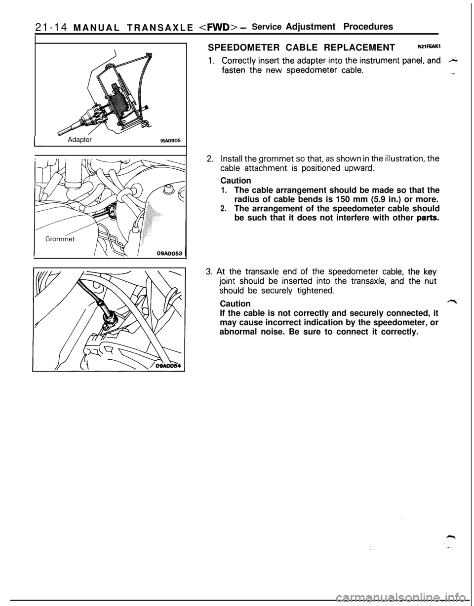
I-Adapter%A0905SPEEDOMETER CABLE REPLACEMENT
NZlFEAKl
1.Correctly insert the adapter into the instrument panel, andS.
fasten the new speedometer cable.1-
2.Install the grommet so that, as shown in the illustration, the
cable attachment is positioned upward.Caution
1.The cable arrangement should be made so that the
radius of cable bends is 150 mm (5.9 in.) or more.
2.The arrangement of the speedometer cable should
be such that it does not interfere with other
parts.
3. At the transaxle end of the speedometer cable, the key
joint should be inserted into the transaxle, and the nut
should be securely tightened.Caution
lllcIf the cable is not correctly and securely connected, it
may cause incorrect indication by the speedometer, or
abnormal noise. Be sure to connect it correctly.
Page 736 of 1216
21-42MANUAL TRANSAXLE
8” in.)TFM0044
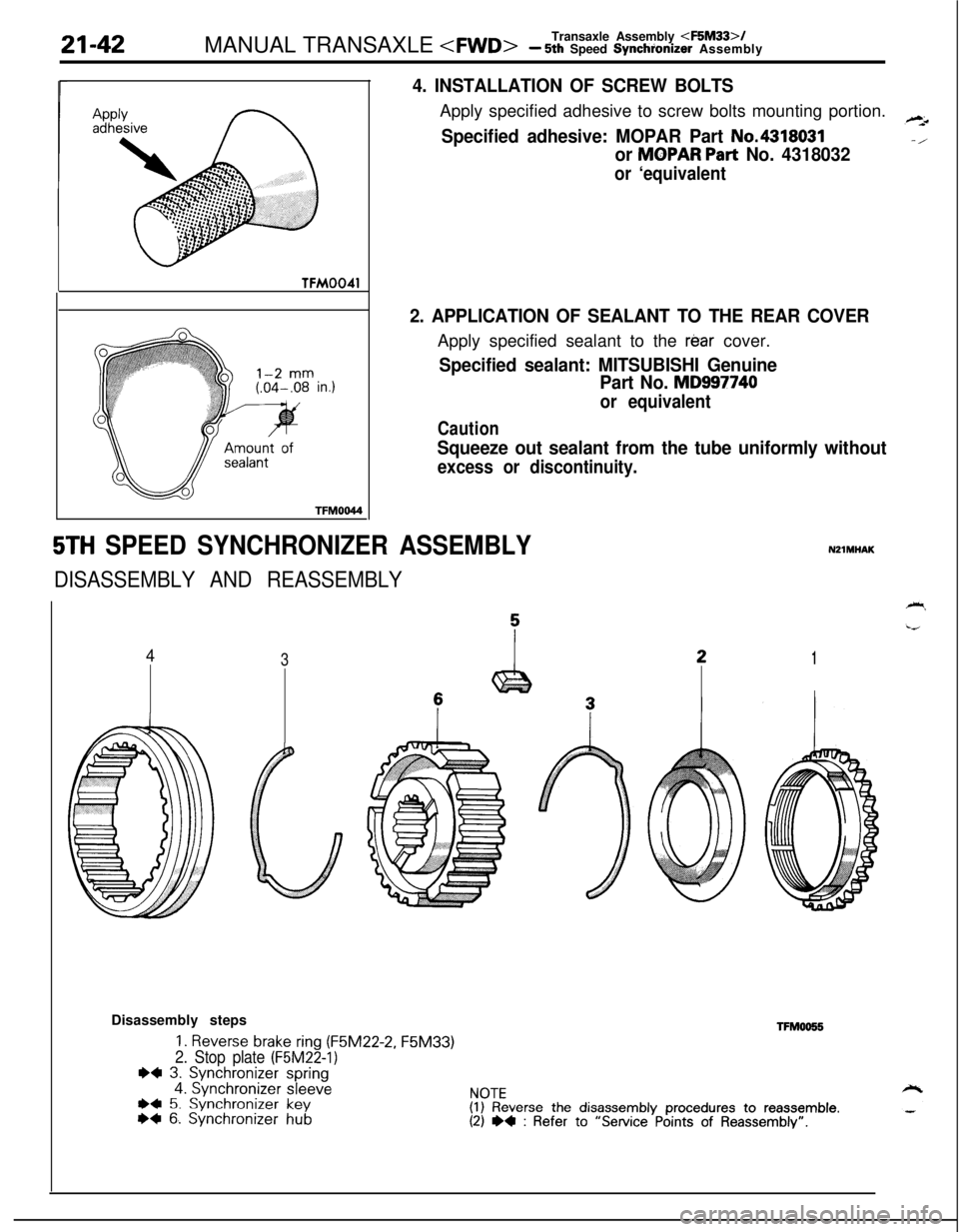
4. INSTALLATION OF SCREW BOLTSApply specified adhesive to screw bolts mounting portion.
Specified adhesive: MOPAR Part No.4318031
or MOPAR Part No. 4318032
or ‘equivalent
2. APPLICATION OF SEALANT TO THE REAR COVERApply specified sealant to the
rear cover.
Specified sealant: MITSUBISHI Genuine
Part No.
MD997740
or equivalent
Caution
Squeeze out sealant from the tube uniformly without
excess or discontinuity.
5TH SPEED SYNCHRONIZER ASSEMBLY
DISASSEMBLY AND REASSEMBLY
43
NZlMHAK
1Disassembly steps
1. Reverse brake ring (F5M22-2, F5M33)
2. Stop plate (F5M22-1)I)4 3. Synchronizer spring4. Synchronizer sleeveWI 5. Synchronizer key*+ 6. Synchronizer hubTFM0055
NOTE(1) Reverse the disassembly procedures to reassemble.(2) ~~ : Refer to “Service Points of Reassembly”.
Page 737 of 1216
..-MANUAL TRANSAXLE
-5th Speed Synchr’onizer Assembly tq-43
201044
201045TFM0046
Springprotrusion
Key
2010018
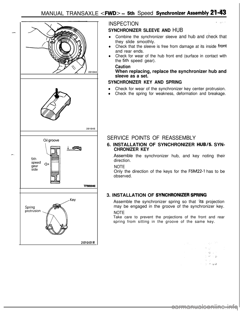
INSPECTION_ -.‘-
SYNCHRONIZER SLEEVE AND HUB-_
lCombine the synchronizer sleeve and hub and check thatthey slide smoothly.
lCheck that the sleeve is free from damage at its inside frontand rear ends.
lCheck for wear of the hub front end (surface in contact withthe
5th speed gear).
CautionWhen replacing, replace the synchronizer hub and
sleeve as a set.
SYNCHRONIZER KEY AND SPRING
lCheck for wear of the synchronizer key center protrusion.
lCheck the spring for weakness, deformation and breakage.
SERVICE POINTS OF REASSEMBLY6. INSTALLATION OF SYNCHRONIZER HUB/5. SYN-
CHRONIZER KEY.Assemble the synchronizer hub, and key noting their
direction.
NOTEOnly the direction of the keys for the
F5M22-1 has to be
observed.3. INSTALLATION OF
SYNCHRONliER $PRlNGAssemble the synchronizer spring so that
:its projection
may be engaged in the groove of the synchronizer key.
NOTETake care to prevent the projections of the front and rear
spring from sitting in the groove of the same key.
Page 738 of 1216
21-44 MANUAL TRANSAXLE
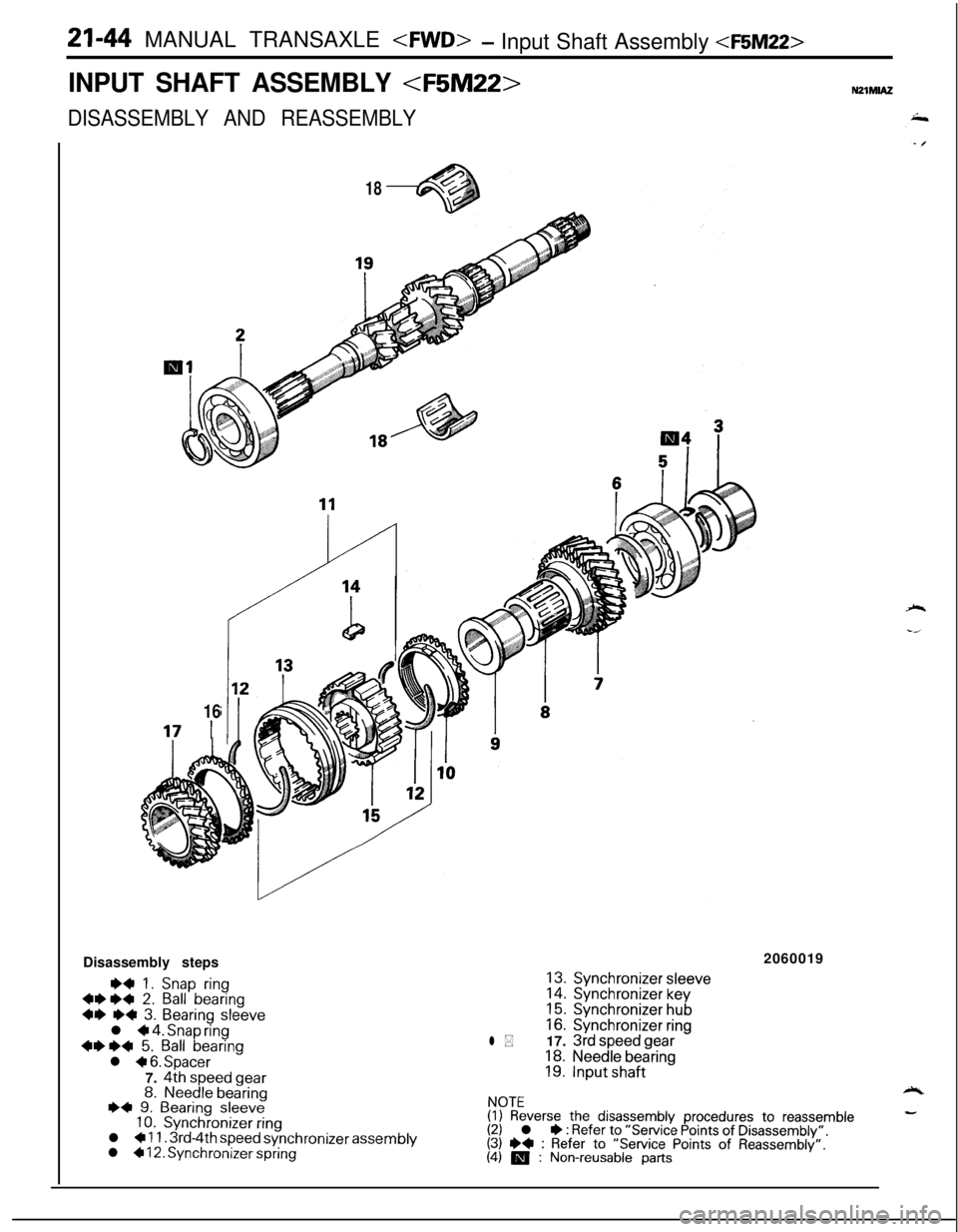
INPUT SHAFT ASSEMBLY
DISASSEMBLY AND REASSEMBLY
18
16
17 IDisassembly steps
*+ 1. Snap ring+1)1)+ 2. Ball bearing
+I) I)+ 3. Bearing sleevel + 4. Snap ring4+*+ 5. Ball bearingl + 6. Spacer
7.
4th speed gear8.Needle bearing~~ 9. Bearing sleeve10.Synchronizer ringl + 11. 3rd-4th speed synchronizer assemblyl + 12. Synchronizer spring2060019
l *
13.Synchronizer sleeve14.Synchronizer key15.Synchronizer hub16.Synchronizer ring
17. 3rd speed gear18.Needle bearing19.Input shaft
NOTE(I) Reverse the disassembly procedures to reassemble(2) l * : Refer to “Service Points of Disassembly”.(3) +* : Refer to “Service Points of Reassembly”.(4) m : Non-reusable parts
Page 740 of 1216
21-46MANUAL TRANSAXLE
201051
TFMO119
Damage, breakage
/
Synchronizer ringGLarTFMOlli
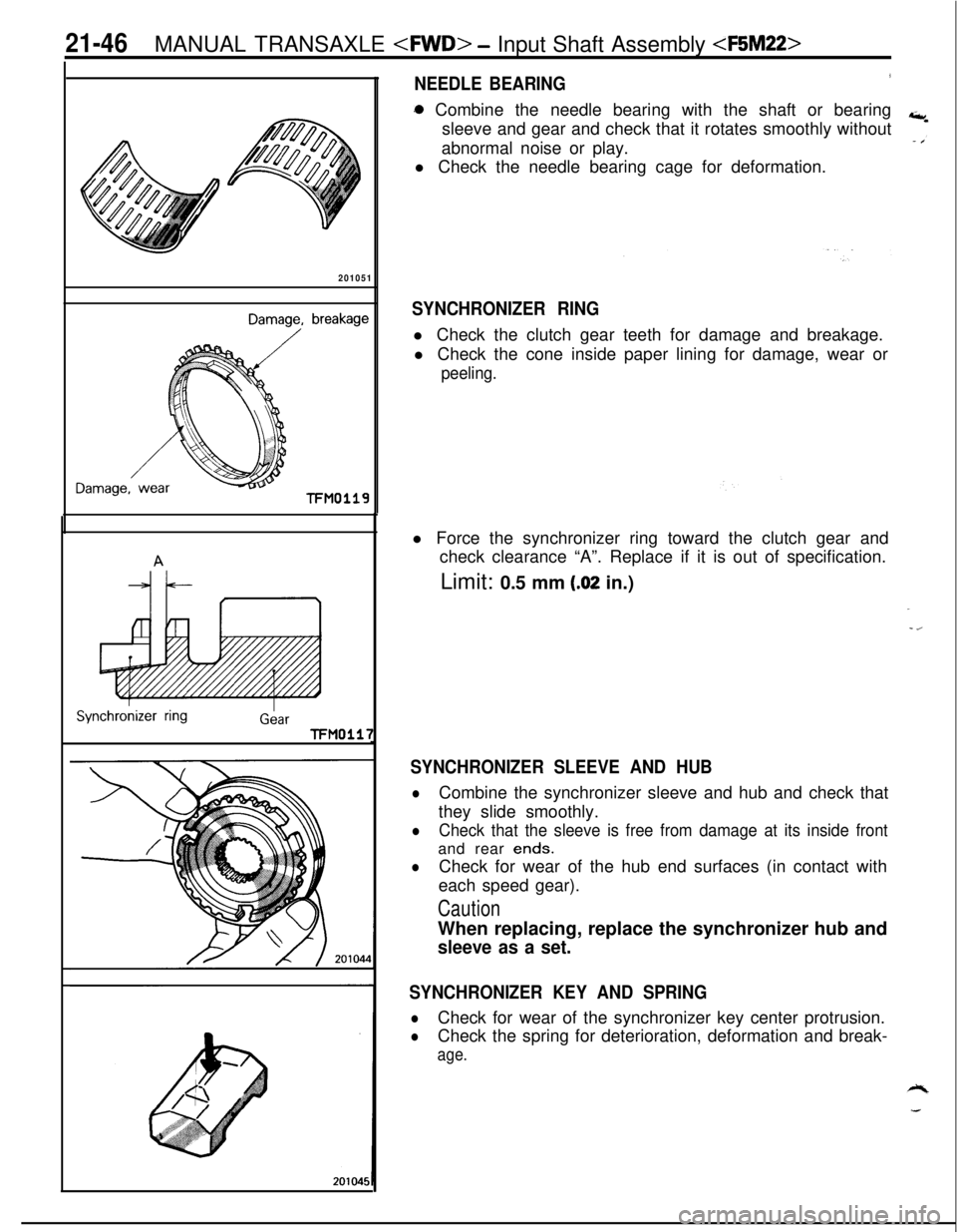
NEEDLE BEARING3a Combine the needle bearing with the shaft or bearing
sleeve and gear and check that it rotates smoothly without
abnormal noise or play.
l Check the needle bearing cage for deformation.
SYNCHRONIZER RINGl Check the clutch gear teeth for damage and breakage.
l Check the cone inside paper lining for damage, wear or
peeling.l Force the synchronizer ring toward the clutch gear and
check clearance “A”. Replace if it is out of specification.
Limit: 0.5 mm
(.02 in.)
SYNCHRONIZER SLEEVE AND HUB
lCombine the synchronizer sleeve and hub and check that
they slide smoothly.
lCheck that the sleeve is free from damage at its inside frontand rear
ends.
lCheck for wear of the hub end surfaces (in contact with
each speed gear).
CautionWhen replacing, replace the synchronizer hub and
sleeve as a set.
SYNCHRONIZER KEY AND SPRING
lCheck for wear of the synchronizer key center protrusion.
lCheck the spring for deterioration, deformation and break-
age.
Page 741 of 1216
MANUAL TRANSAXLE
Springprotrusion2010018TFM0021
MD998320/
SPEED GEARS
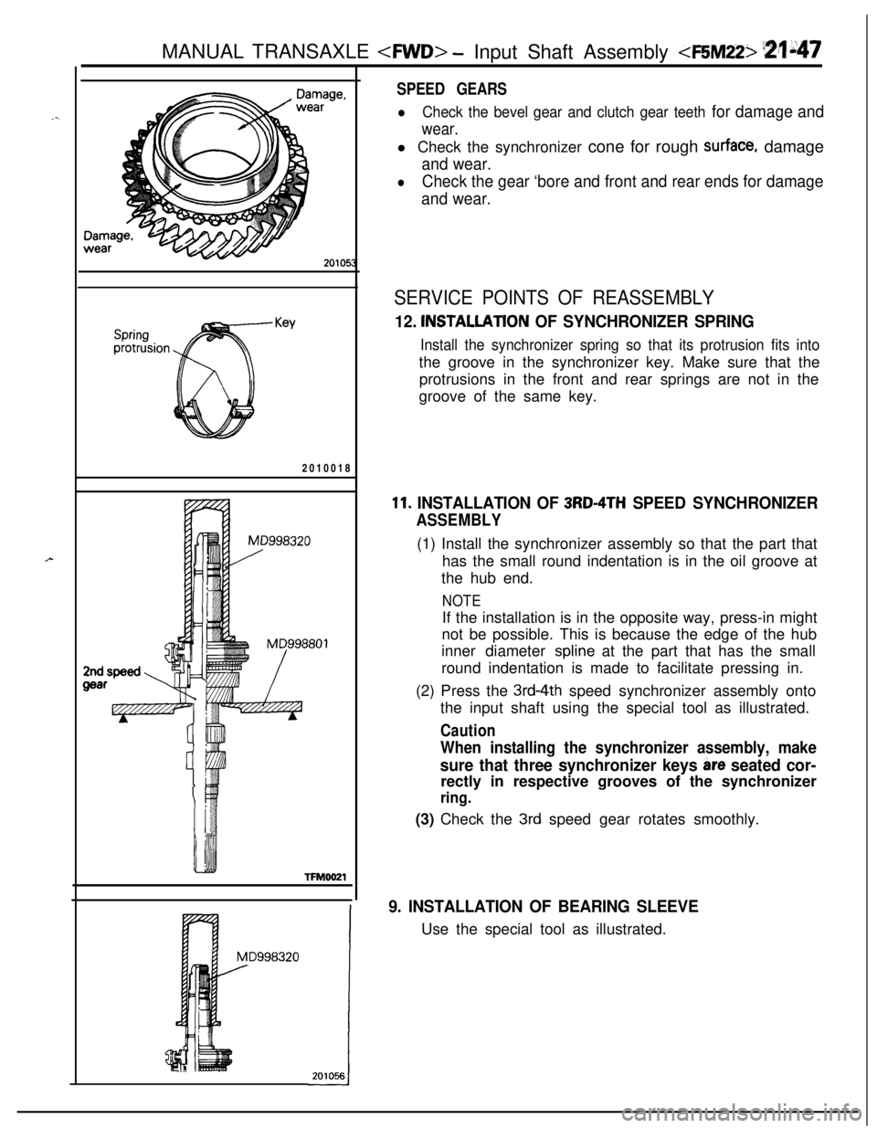
lCheck the bevel gear and clutch gear teeth for damage and
wear.l Check the synchronizer cone for rough
surface, damage
and wear.
lCheck the gear ‘bore and front and rear ends for damage
and wear.
SERVICE POINTS OF REASSEMBLY
12. INSTALLATlON OF SYNCHRONIZER SPRING
Install the synchronizer spring so that its protrusion fits intothe groove in the synchronizer key. Make sure that the
protrusions in the front and rear springs are not in the
groove of the same key.
11. INSTALLATION OF 3RD-4TH SPEED SYNCHRONIZER
ASSEMBLY(1) Install the synchronizer assembly so that the part that
has the small round indentation is in the oil groove at
the hub end.
NOTEIf the installation is in the opposite way, press-in might
not be possible. This is because the edge of the hub
inner diameter
spline at the part that has the small
round indentation is made to facilitate pressing in.
(2) Press the
3rd-4th speed synchronizer assembly onto
the input shaft using the special tool as illustrated.
Caution
When installing the synchronizer assembly, make
sure that three synchronizer keys are seated cor-rectly in respective grooves of the synchronizer
ring.(3) Check the
3rd speed gear rotates smoothly.
9. INSTALLATION OF BEARING SLEEVEUse the special tool as illustrated.
Page 744 of 1216
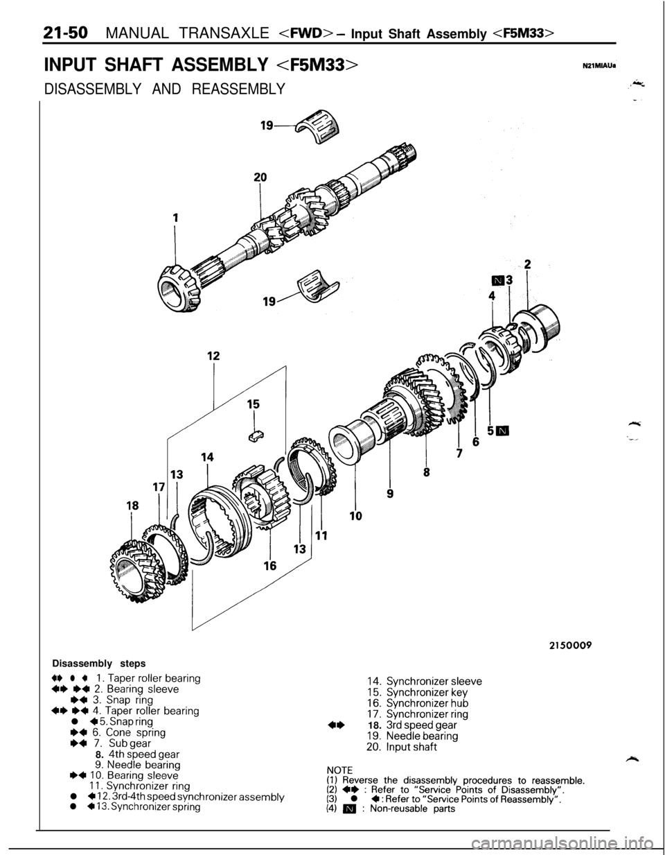
21-50MANUAL TRANSAXLE
INPUT SHAFT ASSEMBLY
DISASSEMBLY AND REASSEMBLYDisassembly steps
+* l +1. Taper roller bearing++ ~~ 2. Bearing sleeve*+ 3. Snap ring++ I)+ 4. Taper roller bearingl + 5. Snap ringI)+ 6. Cone spring
~~ 7. Subgear8. 4th speed gear9. Needle bearing~~ 10. Bearing sleeve11. Synchronizer ringl + 12. 3rd-4th speed synchronizer assemblyl * 13. Synchronizer spring
2150009
14.Synchronizer sleeve
15.Synchronizer key16.Synchronizer hub17.Synchronizer ring
18. 3rd
speed gear
19.Needle bearing20.Input shaft
NOTE(1) Reverse the disassembly procedures to reassemble.(2) ++ : Refer to “Service Points of Disassembly”.(3) l + : Refer to “Service Points of Reassembly”.(4) m : Non-reusable parts
Page 746 of 1216

21-52 MANUAL TRANSAXLE
r
201051
Damage, breakage
Damage,TFMO119
ISynchronver ringGearTFM0117
2010441
NEEDLE BEARINGl Combine the needle bearing with the shaft or bearing
+,sleeve and gear and check that it rotates smoothly without
abnormal noise or play.
l Check the needle bearing cage for deformation.
SYNCHRONIZER RINGl Check the clutch gear teeth for damage and breakage.
l Check the cone inside paper lining for damage, wear or
peeling.l Force the synchronizer ring toward the clutch gear and
check clearance “A”. Replace if it is out of specification.
Limit: 0.5 mm
(.02 in.)
-z
SYNCHRONIZER SLEEVE AND HUB
lCombine the synchronizer sleeve and hub and check that
they slide smoothly.
lCheck that the sleeve is free from damage at its inside frontand rear ends.
lCheck for wear of the hub end surfaces (in contact with
each speed gear).
CautionWhen replacing, replace the synchronizer hub and
sleeve as a set.
SYNCHRONIZER KEY AND SPRING
lCheck for wear of the synchronizer key center protrusion.
lCheck the spring for deterioration, deformation and break-
age.