key MITSUBISHI ECLIPSE 1991 User Guide
[x] Cancel search | Manufacturer: MITSUBISHI, Model Year: 1991, Model line: ECLIPSE, Model: MITSUBISHI ECLIPSE 1991Pages: 1216, PDF Size: 67.42 MB
Page 168 of 1216
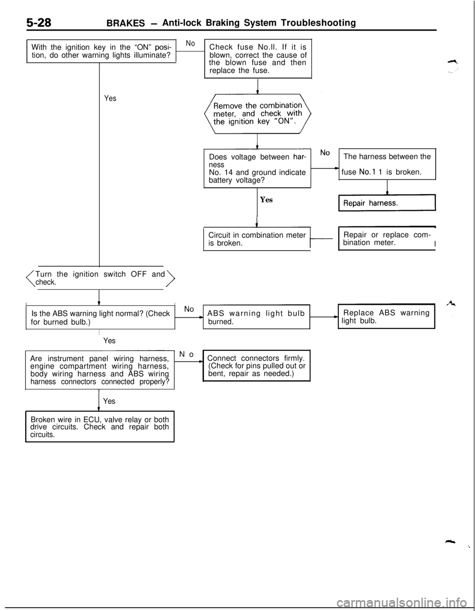
5-28BRAKES -Anti-lock Braking System Troubleshooting
With the ignition key in the “ON”
posi-NoCheck fuse No.ll. If it is
tion, do other warning lights illuminate?blown, correct the cause of
the blown fuse and then
replace the fuse.
YesTurn the ignition switch OFF and
har-NOThe harness between the
nessNo. 14 and ground indicate
battery voltage?) fuse No.1 1 is broken.
YesCircuit in combination meter
is broken.
tRepair or replace com-
bination meter.II
IIIs the ABS warning light normal? (CheckNO) ABS warning light bulbReplace ABS warning
for burned bulb.)
burned.* light bulb.
I
Yes
- No
Are instrument panel wiring harness,
engine compartment wiring harness,
body wiring harness and ABS wiring
harness connectors connected properly?
c Connect connectors firmly.
(Check for pins pulled out or
bent, repair as needed.)
YesBroken wire in ECU, valve relay or both
drive circuits. Check and repair both
circuits.
Page 171 of 1216
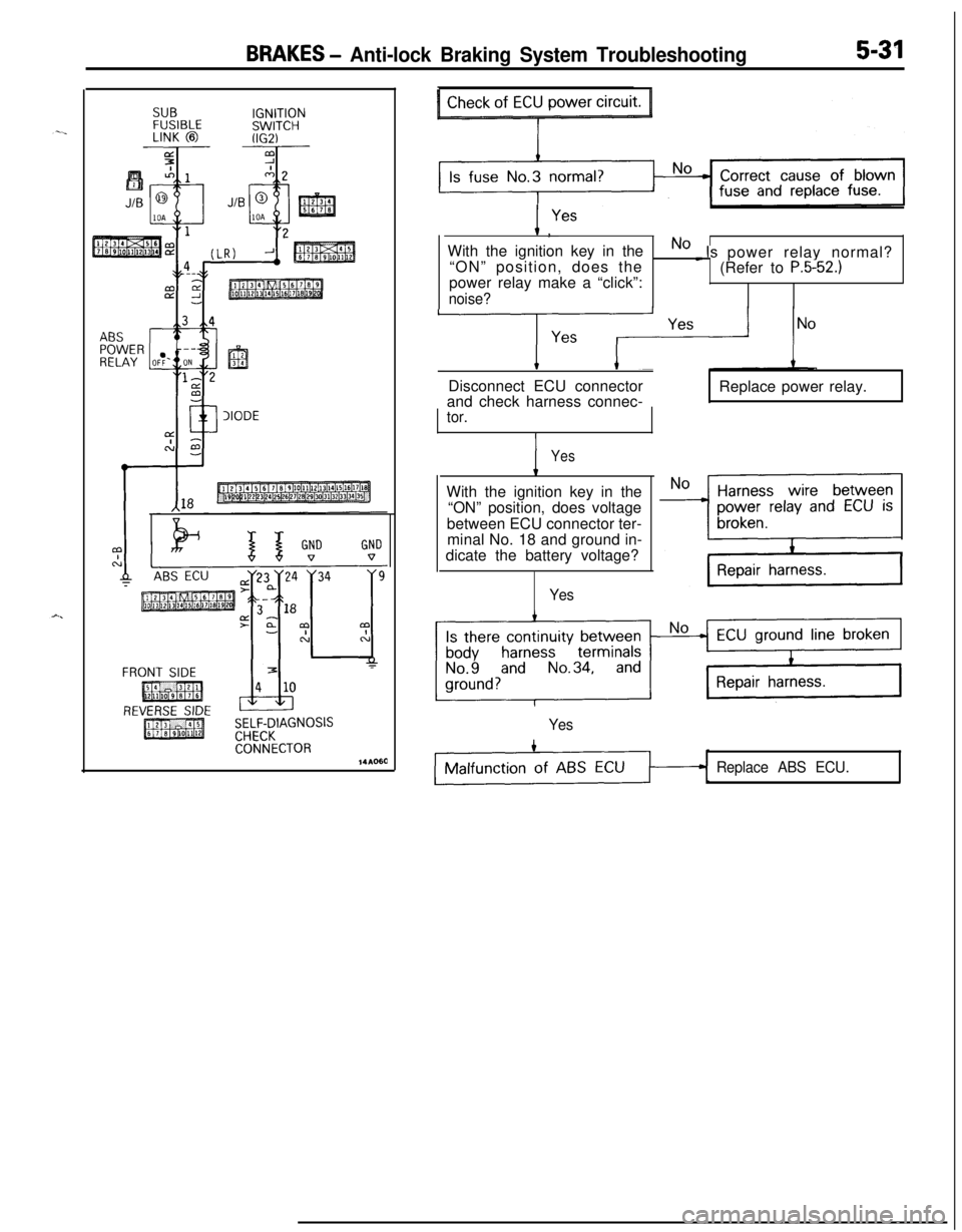
BRAKES - Anti-lock Braking System Troubleshooting5-31
SUBIGNITION
%TB(kEzYCH
IODE
;LLF-FIAGNOSIS
CONNECTOR
I Yes1,
With the ignition key in the
No _ Is power relay normal?
“ON” position, does the
(Refer to P.5-52.)power relay make a “click”:
noise?LDisconnect ECU connector
and check harness connec-Replace power relay.
tor.
YesWith the ignition key in the
“ON” position, does voltage
between ECU connector ter-
minal No. 18 and ground in-
dicate the battery voltage?
Yes
Yes
Replace ABS ECU.
Page 172 of 1216
![MITSUBISHI ECLIPSE 1991 User Guide 5-32BRAKES -Anti-lock Braking System Troubleshooting
CABS warning light does not illuminate when ignition key is in “START” position.
[Explanation]The ABS ECU uses the
IG2 power source which isan MITSUBISHI ECLIPSE 1991 User Guide 5-32BRAKES -Anti-lock Braking System Troubleshooting
CABS warning light does not illuminate when ignition key is in “START” position.
[Explanation]The ABS ECU uses the
IG2 power source which isan](/img/19/57104/w960_57104-171.png)
5-32BRAKES -Anti-lock Braking System Troubleshooting
CABS warning light does not illuminate when ignition key is in “START” position.
[Explanation]The ABS ECU uses the
IG2 power source which isand the ECU turns the valve relay OFF. If the
turned off in the “START” position. The ABSwarning light does not illuminate at this time, there
warning light uses the
IGI power source which isis trouble in the warning light circuit on the valve
not turned off even in the “START” position.relay side.
Consequently, in the “START” position, power is off
MAINIGNITIONFUSIBLESWITCHLINK @I(IGl)J/B
“62
I .1411213141516l7l61911112113114115U6i,79
@COMBINATIONAL METER
“58ABS ECU
1410000
hydraulicunit (HU) connector and
>\/I
1With the ignition key in the
“ON” position, does voltage
between body connector
terminal No.8 and ground
indicate the battery voltage?
Is there continuity between
No~Broken line between HU
body connector terminaland body groundNo.9 and ground?
I
YesIs there continuity between
HU connector terminal No. 8and terminal
No.9?
YesRemove the valve relay. Is
there continuity between
terminal No. 87a and No. 30?
I
Yes1 Replace valve relay.
HU harness malfunction
I
1 Replace HU.
Page 173 of 1216
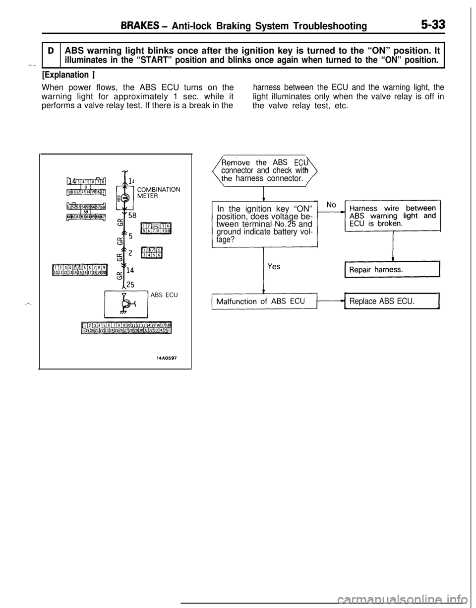
BRAKES - Anti-lock Braking System Troubleshooting5-33
DABS warning light blinks once after the ignition key is turned to the “ON” position. It
illuminates in the “START” position and blinks once again when turned to the “ON” position.*-_
[Explanation ]When power flows, the ABS ECU turns on the
harness between the ECU and the warning light, thewarning light for approximately 1 sec. while itlight illuminates only when the valve relay is off in
performs a valve relay test. If there is a break in the
the valve relay test, etc.
Y
x %l4
9
4
n. 58
ABS ECU
14A0597
EC
4connector and check with
he harness connector. /\/
IIn the ignition key “ON”
position, does voltage be-
tween terminal
No.25 andground indicate battery vol-
tage?
Replace ABS ECU.I
Page 176 of 1216
![MITSUBISHI ECLIPSE 1991 User Guide 5-36BRAKES - Anti-lock Braking System Troubleshooting
E-3Abnormality of G sensor circuit
[Explanation]The ABS ECU turns on the warning light in the
following cases.
lOFF trouble turning G sensor OFF ( MITSUBISHI ECLIPSE 1991 User Guide 5-36BRAKES - Anti-lock Braking System Troubleshooting
E-3Abnormality of G sensor circuit
[Explanation]The ABS ECU turns on the warning light in the
following cases.
lOFF trouble turning G sensor OFF (](/img/19/57104/w960_57104-175.png)
5-36BRAKES - Anti-lock Braking System Troubleshooting
E-3Abnormality of G sensor circuit
[Explanation]The ABS ECU turns on the warning light in the
following cases.
lOFF trouble turning G sensor OFF (It is judged
that the
G sensor continues to be OFF for more
than approximately 13 seconds except when the
lWhen there is a broken wire or short circuit in
the harness for the
G sensor system.
PlUN; F;SIBLEIGNITIONSWITCH (IG2)J/B
G-SENSOR
E-lABSECU
14AO609
Is G sensor normal? (ReferNoto
P.5-86.)Replace G sensor.
I YesWith the ignition key “ON”
_ No m The harness between the
does the voltage betweenG sensor and the ABS
terminal No.6 and groundECU is broken.
indicate battery voltage?
IG sensor circuit is normal.I
Page 325 of 1216
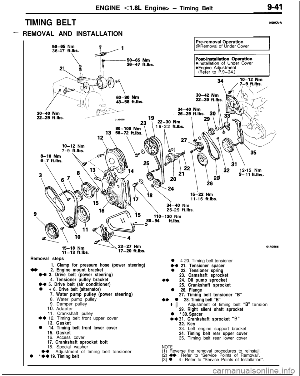
ENGINE <1.8L Engine> - Timing Belt
TIMING BELT
- REMOVAL AND INSTALLATION,
50-65 Nm
36-47 ft.lbs.Pre-removal Operation
@Removal of Under Cover
\ 16-22 ftlbs.\
lo-12 Nm
7-9 ft.lbs.
I28
15-22 Nm
11-16 ft.lbs.
3hO Nm
26-29 ft.lbs.
110-130 Nm(( \\ _ 60-94 ftlbs.
15-16 Nm-23-27 Nm
11-13 ft.lbs.17-20 ft.lbs.12-15 Nm
9- 11 ft.lbs.OlAO555
Removal steps
1. Clamp for pressure hose (power steering)
4*2. Engine mount bracketI)* 3. Drive belt (power steering)
4. Tensioner pulley bracket
H 5. Drive belt (air conditioner)
l + 6. Drive belt (alternator)
7. Water pump pulley (power steering)
8. Water pump pulley
9. Damper pulley
10. Adapter
11. Crankshaft pulley
I)4 12. Timing belt front upper cover
13. Gasket
l 14. Timing belt front lower cover
15. Gasket
16. Access cover
17. Crankshaft sprocket bolt
18. Special washer
Adjustment of timing belt tensioner
l *
:: 19. Timing beltl 4 20. Timing belt tensioner
I)+ 21. Tensioner spacer
l 22. Tensioner spring
23. Camshaft sprocket
4*24. Oil pump sprocket
25. Crankshaft sprocket
l 26. Flange
27. Timing belt tensioner “B”
~~ l 28. Timing belt “B”
l 4Adjustment of timing belt “B” tension
29. Right silent shaft sprocket
l * 30. Spacer
~~ 31. Crankshaft sprocket “B”32. Key
33. Left engine support bracket
34. Timing belt rear upper cover
35. Timing belt rear lower cover
NOTE(1) Reverse the removal procedures to reinstall.
(2)
4* : Refer to “Service Points of Removal”.
(3) l 4 : Refer to “Service Points of Installation”.
Page 513 of 1216
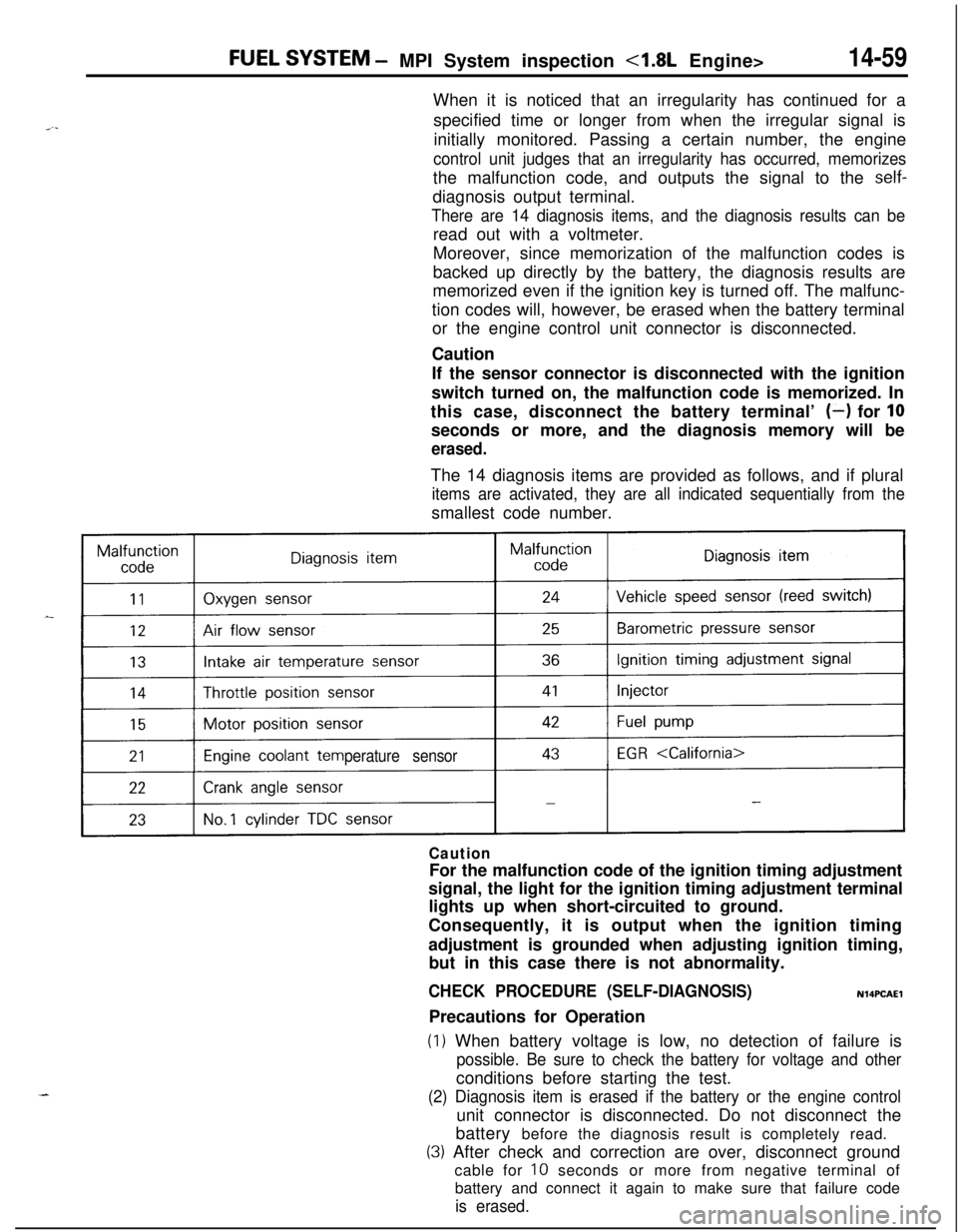
FUEL SYSTEM - MPI System inspection <1.8L Engine>14-59
--..When it is noticed that an irregularity has continued for a
specified time or longer from when the irregular signal is
initially monitored. Passing a certain number, the engine
control unit judges that an irregularity has occurred, memorizesthe malfunction code, and outputs the signal to the
self-diagnosis output terminal.
There are 14 diagnosis items, and the diagnosis results can beread out with a voltmeter.
Moreover, since memorization of the malfunction codes is
backed up directly by the battery, the diagnosis results are
memorized even if the ignition key is turned off. The malfunc-
tion codes will, however, be erased when the battery terminal
or the engine control unit connector is disconnected.
Caution
If the sensor connector is disconnected with the ignition
switch turned on, the malfunction code is memorized. In
this case, disconnect the battery terminal’
(-) for 10seconds or more, and the diagnosis memory will be
erased.The 14 diagnosis items are provided as follows, and if plural
items are activated, they are all indicated sequentially from thesmallest code number.
perature sensor
CautionFor the malfunction code of the ignition timing adjustment
signal, the light for the ignition timing adjustment terminal
lights up when short-circuited to ground.
Consequently, it is output when the ignition timing
adjustment is grounded when adjusting ignition timing,
but in this case there is not abnormality.
CHECK PROCEDURE (SELF-DIAGNOSIS)N14PCAElPrecautions for Operation
(1) When battery voltage is low, no detection of failure is
possible. Be sure to check the battery for voltage and otherconditions before starting the test.
(2) Diagnosis item is erased if the battery or the engine controlunit connector is disconnected. Do not disconnect the
battery before the diagnosis result is completely read.
(3) After check and correction are over, disconnect ground
cable for
10 seconds or more from negative terminal of
battery and connect it again to make sure that failure code
is erased.
Page 527 of 1216
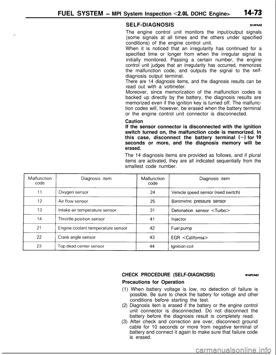
FUEL SYSTEM - MPI System Inspection <2.0L DOHC Engine>
SELF-DIAGNOSIS14-73
N14PAAEThe engine control unit monitors the input/output signals
(some signals at all times and the others under specified
conditions) of the engine control unit.
When it is noticed that an irregularity has continued for a
specified time or longer from when the irregular signal is
initially monitored. Passing a certain number, the engine
control unit judges that an irregularity has occurred, memorizesthe malfunction code, and outputs the signal to the
self-diagnosis output terminal.
There are 14 diagnosis items, and the diagnosis results can beread out with a voltmeter.
Moreover, since memorization of the malfunction codes is
backed up directly by the battery, the diagnosis results are
memorized even if the ignition key is turned off. The malfunc-
tion codes will, however, be erased when the battery terminal
or the engine control unit connector is disconnected.
CautionIf the sensor connector is disconnected with the ignition
switch turned on, the malfunction code is memorized. In
this case, disconnect the battery terminal
(-) for 10seconds or more, and the diagnosis memory will be
erased.The 14 diagnosis items are provided as follows, and if plural
items are activated, they are all indicated sequentially from thesmallest code number.
arometnc pressure sensor
CHECK PROCEDURE (SELF-DIAGNOSIS)Precautions for OperationN14PCAE2(1) When battery voltage is low, no detection of failure is
possible. Be sure to check the battery for voltage and otherconditions before starting the test.
(2) Diagnosis item is erased if the battery or the engine controlunit connector is disconnected. Do not disconnect the
battery before the diagnosis result is completely read.
(3) After check and correction are over, disconnect ground
cable for 10 seconds or more from negative terminal of
battery and connect it again to make sure that failure code
is erased.
Page 589 of 1216
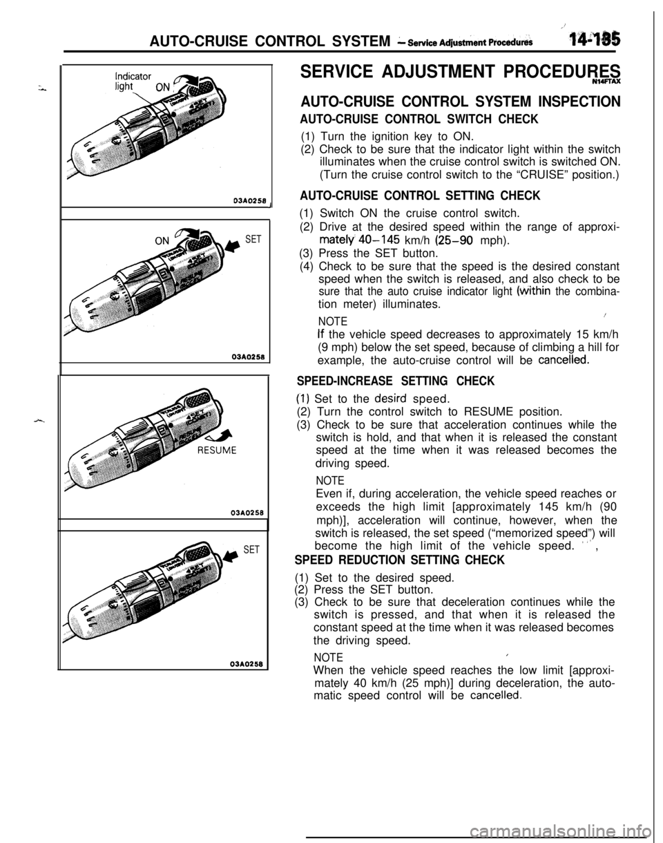
AUTO-CRUISE CONTROL SYSTEM L service Adjustkt Procedw&
03A0258
YSET
03AO258
03AO250
SET
03A025t
JI
SERVICE ADJUSTMENT PROCEDURESNl4FUU
AUTO-CRUISE CONTROL SYSTEM INSPECTION
AUTO-CRUISE CONTROL SWITCH CHECK(1) Turn the ignition key to ON.
(2) Check to be sure that the indicator light within the switch
illuminates when the cruise control switch is switched ON.
(Turn the cruise control switch to the “CRUISE” position.)
AUTO-CRUISE CONTROL SETTING CHECK(1) Switch ON the cruise control switch.
(2) Drive at the desired speed within the range of approxi-
mately 40-145 km/h (25-90 mph).
(3) Press the SET button.
(4) Check to be sure that the speed is the desired constant
speed when the switch is released, and also check to be
sure that the auto cruise indicator light (tithin the combina-tion meter) illuminates.
NOTE1(
If the vehicle speed decreases to approximately 15 km/h
(9 mph) below the set speed, because of climbing a hill for
example, the auto-cruise control will be
cancelled.
SPEED-INCREASE SETTING CHECK
(‘1) Set to the desird speed.
(2) Turn the control switch to RESUME position.
(3) Check to be sure that acceleration continues while the
switch is hold, and that when it is released the constant
speed at the time when it was released becomes the
driving speed.
NOTEEven if, during acceleration, the vehicle speed reaches or
exceeds the high limit [approximately 145 km/h (90
mph)], acceleration will continue, however, when the
switch is released, the set speed (“memorized speed”) will
become the high limit of the vehicle speed.
’ ” ,
SPEED REDUCTION SETTING CHECK(1) Set to the desired speed.
(2) Press the SET button.
(3) Check to be sure that deceleration continues while the
switch is pressed, and that when it is released the
constant speed at the time when it was released becomes
the driving speed.
NOTEIWhen the vehicle speed reaches the low limit [approxi-
mately 40 km/h (25 mph)] during deceleration, the auto-
matic speed control will be
cancelled.
Page 664 of 1216
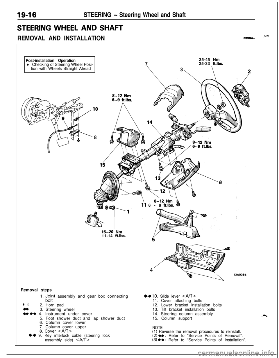
19-16STEERING - Steering Wheel and Shaft
STEERING WHEEL AND SHAFT
REMOVAL AND INSTALLATIONNlL)GA- ‘-
Post-installation Operationl Checking of Steering Wheel Posi-
tion with Wheels Straight Ahead
835-45 Nm
725-33 ft.lbs.
\
3
\\
15-20 Nm
11-14 ft.lbs.Removal steps
1.
“,c$t assembly and gear box connecting
l *2. Horn pad
4*3. Steering wheel
+* ++ 4. Instrument under cover
5. Foot shower duct and lap shower duct
6. Column cover lower
7. Column cover upper
8. Cover
assembly side)
\8-i2 Nm’11 6-9 ft.lbs.0
413AO296
+4 10. Slide lever 11. Cover attaching bolts
12. Lower bracket installation bolts
13. Tilt bracket installation bolts
14. Steering column assembly
15. Column support
NOTE(I) Reverse the removal procedures to reinstall.(2) a* : Refer to “Service Points of Removal”.(3) +a : Refer to “Service Points of Installation”.