key MITSUBISHI ECLIPSE 1991 Workshop Manual
[x] Cancel search | Manufacturer: MITSUBISHI, Model Year: 1991, Model line: ECLIPSE, Model: MITSUBISHI ECLIPSE 1991Pages: 1216, PDF Size: 67.42 MB
Page 808 of 1216
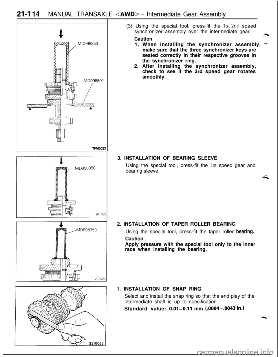
21-I 14MANUAL TRANSAXLE
synchronizer assembly over the intermediate gear.
fkCaution1. When installing the synchronizer assembly,
-imake sure that the three synchronizer keys are
seated correctly in their respective grooves in
the synchronizer ring.
2. After installing the synchronizer assembly,
check to see if the
3rd speed gear rotates
smoothly.
TFM0023,
MD9983503. INSTALLATION OF BEARING SLEEVE
Using the special tool, press-fit the 1st speed gear and
bearing sleeve.
42. INSTALLATION OF TAPER ROLLER BEARING
Using the special tool, press-fit the taper roller bearing.
Caution
Apply pressure with the special tool only to the inner
race when installing the bearing.
1. INSTALLATION OF SNAP RING
Select and install the snap ring so that the end play of the
intermediate shaft is up to specification.
Standard value:
0.01-0.11 mm (.0004-.OO43 in.)
Page 809 of 1216
MANUAL TRANSAXLE
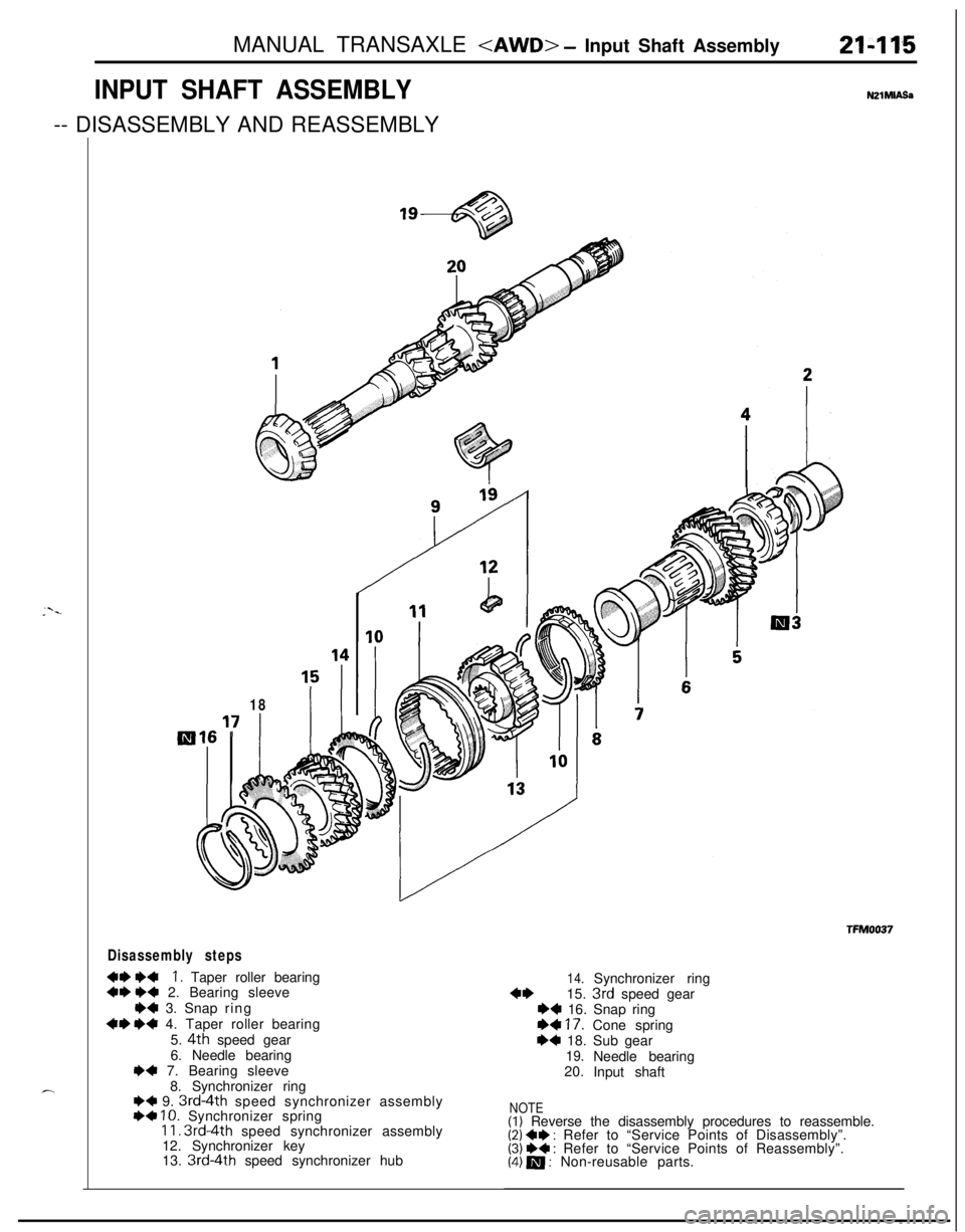
INPUT SHAFT ASSEMBLY-- DISASSEMBLY AND REASSEMBLYNZlMlASa
18
Disassembly steps
+e I)+I. Taper roller bearing~~ I)4 2. Bearing sleeve
*4 3. Snap ring
+e I)+ 4. Taper roller bearing
5.
4th speed gear
6. Needle bearing
I)+ 7. Bearing sleeve
8. Synchronizer ring
I)+ 9. 3rd-4th speed synchronizer assembly++ IO. Synchronizer spring11. 3rd4th speed synchronizer assembly
12. Synchronizer key
13.
3rd-4th speed synchronizer hub
14.Synchronizer ring
4*15. 3rd speed gear++ 16. Snap ring
+* 17. Cone spring+4 18. Sub gear19.Needle bearing
20.
Input shaft
NOTE(1) Reverse the disassembly procedures to reassemble.(2) +e : Refer to “Service Points of Disassembly”.(3) +* : Refer to “Service Points of Reassembly”.(4) m : Non-reusable parts.
Page 811 of 1216
MANUAL TRANSAXLE
_.Damage, breakage
TFMO119Synchronizer ring
GearTFM0117
20104~
201045
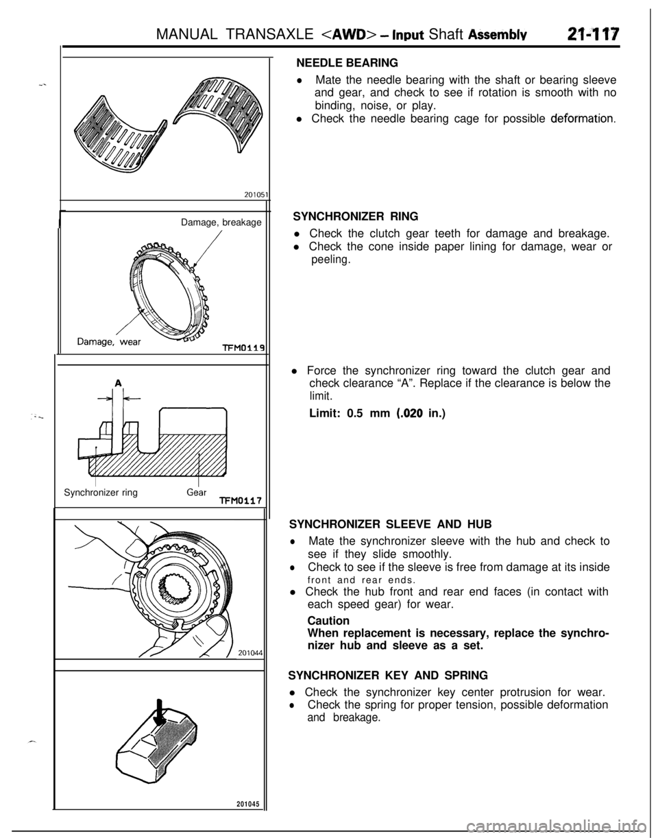
1NEEDLE BEARING
lMate the needle bearing with the shaft or bearing sleeve
and gear, and check to see if rotation is smooth with no
binding, noise, or play.
l Check the needle bearing cage for possible
deformation.SYNCHRONIZER RING
l Check the clutch gear teeth for damage and breakage.
l Check the cone inside paper lining for damage, wear or
peeling.l Force the synchronizer ring toward the clutch gear and
check clearance “A”. Replace if the clearance is below the
limit.Limit: 0.5 mm
(.020 in.)
SYNCHRONIZER SLEEVE AND HUB
lMate the synchronizer sleeve with the hub and check to
see if they slide smoothly.
lCheck to see if the sleeve is free from damage at its inside
front and rear ends.
l Check the hub front and rear end faces (in contact with
each speed gear) for wear.
Caution
When replacement is necessary, replace the synchro-
nizer hub and sleeve as a set.
SYNCHRONIZER KEY AND SPRING
l Check the synchronizer key center protrusion for wear.
lCheck the spring for proper tension, possible deformation
and breakage.
Page 812 of 1216
MANUAL TRANSAXLE
vear210018
Springprotrusion
Key
201001::
TFM0023
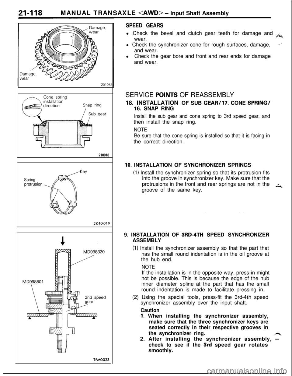
SPEED GEARSl Check the bevel and clutch gear teeth for damage and
.6
wear.l Check the synchronizer cone for rough surfaces, damage,
-‘and wear.
lCheck the gear bore and front and rear ends for damage
and wear.
SERVICE POlNTS OF REASSEMBLY18. INSTALLATION OF SUB
GEAR/17. CONE SPRING/16. SNAP RING
Install the sub gear and cone spring to 3rd speed gear, andthen install the snap ring.
NOTE
Be sure that the cone spring is installed so that it is facing inthe correct direction.
10. INSTALLATION OF SYNCHRONIZER SPRINGS
(1) Install the synchronizer spring so that its protrusion fits
into the groove in synchronizer key. Make sure that the
protrusions in the front and rear springs are not in the
in,groove of the same key.
9. INSTALLATION OF
3RD-4TH SPEED SYNCHRONIZER
ASSEMBLY
(1) Install the synchronizer assembly so that the part that
has the small round indentation is in the oil groove at
the hub end.
NOTEIf the installation is in the opposite way, press-in might
not be possible. This is because the edge of the hub
inner diameter
spline at the part that has the small
round indentation is made to facilitate pressing in.
(2) Using the special tools, press-fit the
3rd-4th speed
synchronizer assembly over the input shaft.
Caution
1. When installing the synchronizer assembly,
make sure that the three synchronizer keys are
seated correctly in their respective grooves in
the synchronizer ring.
h2. After installing the synchronizer assembly, --
check to see if the
3rd speed gear rotates
smoothly.
Page 862 of 1216
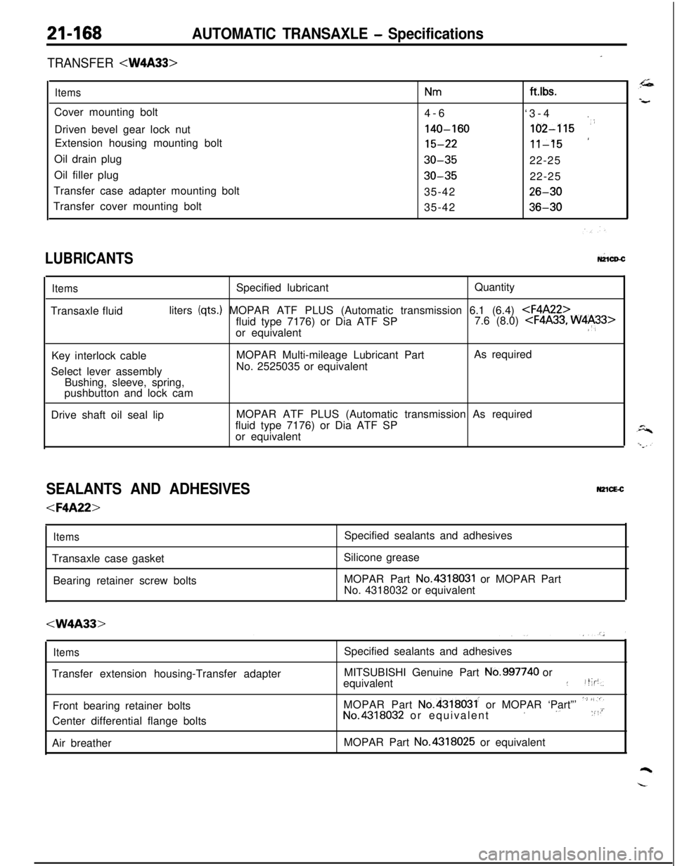
21-168AUTOMATIC TRANSAXLE - Specifications
-TRANSFER
ItemsNmCover mounting bolt
4-6
Driven bevel gear lock nut
140-160Extension housing mounting bolt
15-22Oil drain plug
30-35Oil filler plug
30-35Transfer case adapter mounting bolt
35-42
Transfer cover mounting bolt
35-42ft.lbs.
‘3-4
.
162-115 ‘i
‘11-1522-25
22-25
26-30
36-30
LUBRICANTSW1CD-C
ItemsSpecified lubricantQuantity
Transaxle fluidliters
(qts.) MOPAR ATF PLUS (Automatic transmission 6.1 (6.4)
or equivalent
:‘,Key interlock cableMOPAR Multi-mileage Lubricant PartAs required
Select lever assemblyNo. 2525035 or equivalent
Bushing, sleeve, spring,
pushbutton and lock cam
Drive shaft oil seal lipMOPAR ATF PLUS (Automatic transmission As required
fluid type 7176) or Dia ATF SP
or equivalent
SEALANTS AND ADHESIVESN2lcE-c
ItemsTransaxle case gasket
Bearing retainer screw bolts
Silicone grease
MOPAR Part
No.4318031 or MOPAR Part
No. 4318032 or equivalent
ItemsTransfer extension housing-Transfer adapter
Front bearing retainer bolts
Center differential flange bolts
Air breatherSpecified sealants and adhesives
MITSUBISHI Genuine Part
No.997740 or
equivalent::t;p,
MOPAR Part
No.4318031. or MOPAR ‘Part”’ ‘~’ “,“iNo.4318032 or equivalent’ ‘. :“’MOPAR Part No.4318025 or equivalent
Page 872 of 1216
21-178AUTOMATIC TRANSAXLE - Troubleshooting
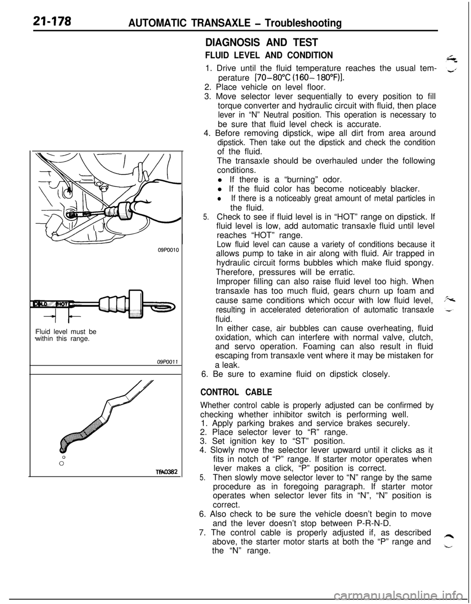
09P0010Fluid level must be
within this range.09PoOll
0”
Two302
DIAGNOSIS AND TEST
FLUID LEVEL AND CONDITION1. Drive until the fluid temperature reaches the usual tem-
perature
[70-80°C (160- 18O”F)I.2. Place vehicle on level floor.
3. Move selector lever sequentially to every position to fill
torque converter and hydraulic circuit with fluid, then place
lever in “N” Neutral position. This operation is necessary tobe sure that fluid level check is accurate.
4. Before removing dipstick, wipe all dirt from area around
dipstick. Then take out the dipstick and check the conditionof the fluid.
The transaxle should be overhauled under the following
conditions.l If there is a “burning” odor.
l If the fluid color has become noticeably blacker.
lIf there is a noticeably great amount of metal particles inthe fluid.
5.Check to see if fluid level is in “HOT” range on dipstick. If
fluid level is low, add automatic transaxle fluid until level
reaches “HOT” range.
Low fluid level can cause a variety of conditions because itallows pump to take in air along with fluid. Air trapped in
hydraulic circuit forms bubbles which make fluid spongy.
Therefore, pressures will be erratic.
Improper filling can also raise fluid level too high. When
transaxle has too much fluid, gears churn up foam and
cause same conditions which occur with low fluid level,
resulting in accelerated deterioration of automatic transaxle
fluid.In either case, air bubbles can cause overheating, fluid
oxidation, which can interfere with normal valve, clutch,
and servo operation. Foaming can also result in fluid
escaping from transaxle vent where it may be mistaken for
a leak.
6. Be sure to examine fluid on dipstick closely.
CONTROL CABLE
Whether control cable is properly adjusted can be confirmed bychecking whether inhibitor switch is performing well.
1. Apply parking brakes and service brakes securely.
2. Place selector lever to “R” range.
3. Set ignition key to “ST” position.
4. Slowly move the selector lever upward until it clicks as it
fits in notch of “P” range. If starter motor operates when
lever makes a click, “P” position is correct.
5.Then slowly move selector lever to “N” range by the same
procedure as in foregoing paragraph. If starter motor
operates when selector lever fits in “N”, “N” position is
correct.6. Also check to be sure the vehicle doesn’t begin to move
and the lever doesn’t stop between P-R-N-D.
7. The control cable is properly adjusted if, as described
above, the starter motor starts at both the “P” range and
the “N” range.
Page 873 of 1216
AUTOMATIC TRANSAXLE - Troubleshooting21-179
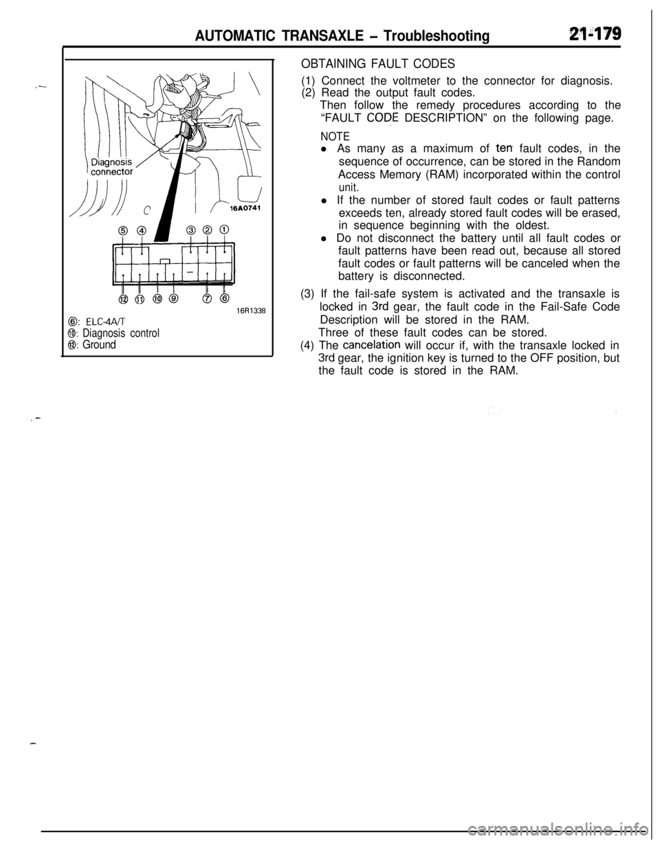
@: ELC-4PJT
@I: Diagnosis control
0: Ground
16R1336
OBTAINING FAULT CODES(1) Connect the voltmeter to the connector for diagnosis.
(2) Read the output fault codes.
Then follow the remedy procedures according to the
“FAULT
CODE DESCRIPTION” on the following page.
NOTEl As many as a maximum of
terr fault codes, in the
sequence of occurrence, can be stored in the Random
Access Memory (RAM) incorporated within the control
unit.l If the number of stored fault codes or fault patterns
exceeds ten, already stored fault codes will be erased,
in sequence beginning with the oldest.
l Do not disconnect the battery until all fault codes or
fault patterns have been read out, because all stored
fault codes or fault patterns will be canceled when the
battery is disconnected.
(3) If the fail-safe system is activated and the transaxle is
locked in
3rd gear, the fault code in the Fail-Safe Code
Description will be stored in the RAM.
Three of these fault codes can be stored.
(4) The
cancelation will occur if, with the transaxle locked in
3rd gear, the ignition key is turned to the OFF position, but
the fault code is stored in the RAM.
Page 904 of 1216
21-210AUTOMATIC TRANSAXLE - Service Adjustment Procedures
OSA0141
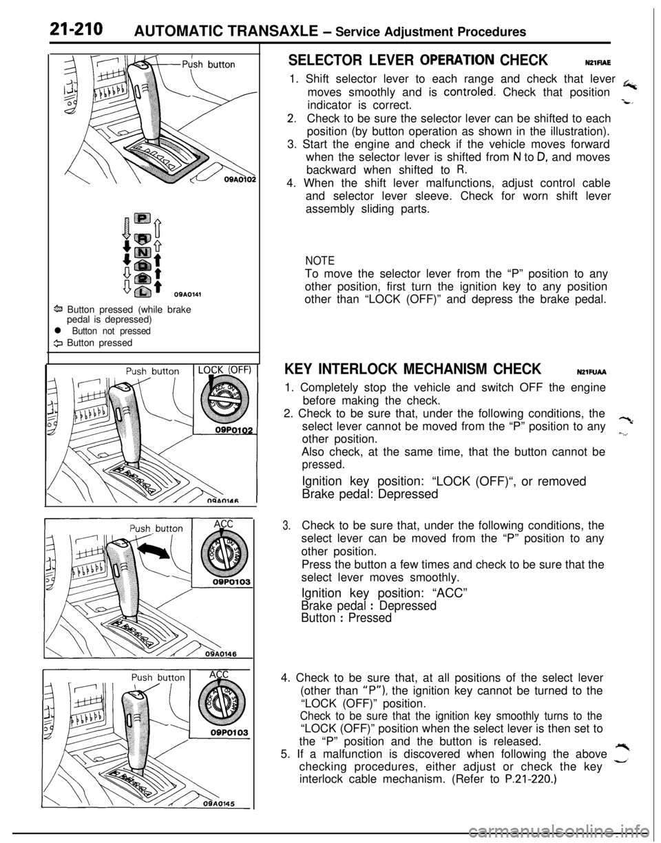
ti Button pressed (while brake
pedal is depressed)
l Button not pressed
9 Button pressed
SELECTOR LEVER OPERATlON CHECKNZlFlAE1. Shift selector lever to each range and check that lever
+moves smoothly and is controled. Check that position
indicator is correct.
-L*
2.Check to be sure the selector lever can be shifted to each
position (by button operation as shown in the illustration).
3. Start the engine and check if the vehicle moves forward
when the selector lever is shifted from
N to D, and moves
backward when shifted to
R.4. When the shift lever malfunctions, adjust control cable
and selector lever sleeve. Check for worn shift lever
assembly sliding parts.
NOTETo move the selector lever from the “P” position to any
other position, first turn the ignition key to any position
other than “LOCK (OFF)” and depress the brake pedal.
KEY INTERLOCK MECHANISM CHECKNZlFUAA1. Completely stop the vehicle and switch OFF the engine
before making the check.
2. Check to be sure that, under the following conditions, the
select lever cannot be moved from the “P” position to any
?cother position.
~.‘,Also check, at the same time, that the button cannot be
pressed.Ignition key position:
“LOCK (OFF)“, or removed
Brake pedal: Depressed
3.Check to be sure that, under the following conditions, the
select lever can be moved from the “P” position to any
other position.
Press the button a few times and check to be sure that the
select lever moves smoothly.
Ignition key position: “ACC”
Brake pedal : Depressed
Button
: Pressed4. Check to be sure that, at all positions of the select lever
(other than
“P”), the ignition key cannot be turned to the
“LOCK (OFF)” position.
Check to be sure that the ignition key smoothly turns to the“LOCK (OFF)” position when the select lever is then set to
the “P” position and the button is released.
5. If a malfunction is discovered when following the above
,”checking procedures, either adjust or check the key
interlock cable mechanism. (Refer to
P.21-220.)
Page 905 of 1216
AUTOMATIC TRANSAXLE - Service Adjustment Procedures21-21109A0146
OQMOO45
control lever
control lever
5 mm
Section A-A
(2 in.)Manual
controllever
Switch body
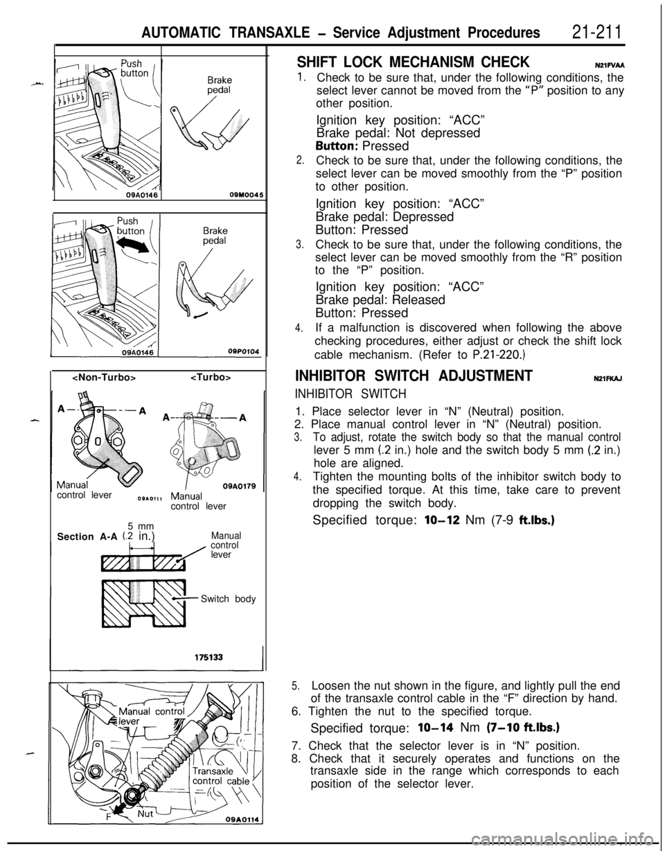
SHIFT LOCK MECHANISM CHECKN21FVAA
1.
2.
3.
4.Check to be sure that, under the following conditions, the
select lever cannot be moved from the
“P” position to any
other position.
Ignition key position: “ACC”
Brake pedal: Not depressedButton: Pressed
Check to be sure that, under the following conditions, the
select lever can be moved smoothly from the “P” position
to other position.
Ignition key position: “ACC”
Brake pedal: Depressed
Button: Pressed
Check to be sure that, under the following conditions, the
select lever can be moved smoothly from the “R” position
to the “P” position.
Ignition key position: “ACC”
Brake pedal: Released
Button: Pressed
If a malfunction is discovered when following the above
checking procedures, either adjust or check the shift lock
cable mechanism. (Refer to
P.21-220.)
INHIBITOR SWITCH ADJUSTMENTNZlFKAJ
INHIBITOR SWITCH1. Place selector lever in “N” (Neutral) position.
2. Place manual control lever in “N” (Neutral) position.
3.To adjust, rotate the switch body so that the manual controllever 5 mm
(2 in.) hole and the switch body 5 mm (.2 in.)
hole are aligned.
4.Tighten the mounting bolts of the inhibitor switch body to
the specified torque. At this time, take care to prevent
dropping the switch body.
Specified torque:
lo-12 Nm (7-9 ftlbs.)
5.Loosen the nut shown in the figure, and lightly pull the end
of the transaxle control cable in the “F” direction by hand.
6. Tighten the nut to the specified torque.
Specified torque:
IO-14 Nm (7-10 ftlbs.)7. Check that the selector lever is in “N” position.
8. Check that it securely operates and functions on the
transaxle side in the range which corresponds to each
position of the selector lever.
Page 910 of 1216
21-216AUTOMATIC TRANSAXLE - Service Adjustment Procedures
I16A0905
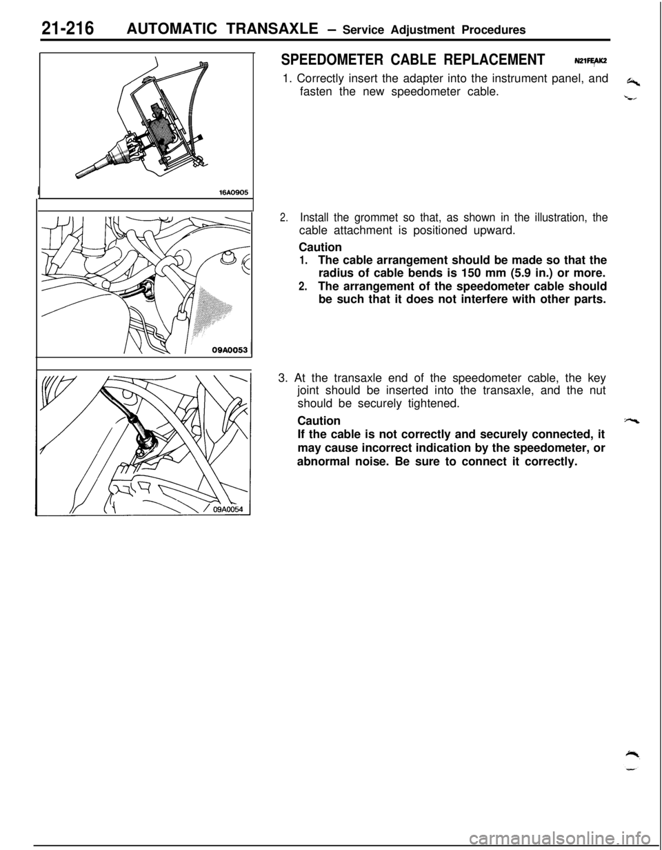
SPEEDOMETER CABLE REPLACEMENTN21FEAK2,1. Correctly insert the adapter into the instrument panel, and
+fasten the new speedometer cable.
t,
2.Install the grommet so that, as shown in the illustration, thecable attachment is positioned upward.
Caution
1.The cable arrangement should be made so that the
radius of cable bends is 150 mm (5.9 in.) or more.
2.The arrangement of the speedometer cable should
be such that it does not interfere with other parts.
3. At the transaxle end of the speedometer cable, the key
joint should be inserted into the transaxle, and the nut
should be securely tightened.
Caution
“ccIf the cable is not correctly and securely connected, it
may cause incorrect indication by the speedometer, or
abnormal noise. Be sure to connect it correctly.