key MITSUBISHI ECLIPSE 1991 Owner's Guide
[x] Cancel search | Manufacturer: MITSUBISHI, Model Year: 1991, Model line: ECLIPSE, Model: MITSUBISHI ECLIPSE 1991Pages: 1216, PDF Size: 67.42 MB
Page 747 of 1216
MANUAL TRANSAXLE
2010018
2ndgearTFM0024
MD998320
20105f
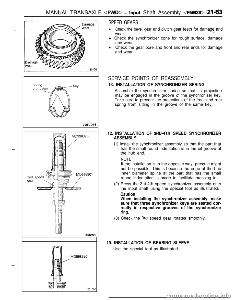
SPEED GEARS
lCheck the bevel gear and clutch gear teeth for damage andw.wear.l Check the synchronizer cone for rough surface, damage
and wear.
lCheck the gear bore and front and rear ends for damage
and wear.
SERVICE POINTS OF REASSEMBLY
13. INSTALLATION OF SYNCHRONIZER SPRINGAssemble the synchronizer spring so that its projection
may be engaged in the groove of the synchronizer key.
Take care to prevent the projections of the front and rear
spring from sitting in the groove of the same key.
12. INSTALLATION OF 3RD-4TH SPEED SYNCHRONIZER
ASSEMBLY
(1) Install the synchronizer assembly so that the part that
has the small round indentation is in the oil groove at
the hub end.
NOTEIf the installation is in the opposite way, press-in might
not be possible. This is because the edge of the hub
inner diameter spline at the part that has the small
round indentation is made to facilitate pressing in.
(2) Press the
3rd-4th speed synchronizer assembly onto
the input shaft using the special tool as illustrated.
Caution
When installing the synchronizer assembly, make
sure that three synchronizer keys are seated cor-rectly in respective grooves of the synchronizer
ring.(3) Check the
3rd speed gear rotates smoothly.
10. INSTALLATION OF BEARING SLEEVEUse the special tool as illustrated.
j
Page 750 of 1216
21-56MANUAL TRANSAXLE
INTERMEDIATE GEAR ASSEMBLYNZlhlJAd
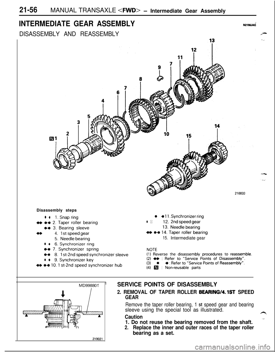
DISASSEMBLY AND REASSEMBLYDisassembly steps
l *1. Snap ring
w *+ 2. Taper roller bearing
w 3. Bearing sleeve
4*4.1 st speed gear
5.Needle bearing
l +6. Synchronizer ring
ea 7. Synchronizer spring
w8.1 st-2nd speed synchronizersleeve
l *9. Synchronizer key
+* ~~ 10. 1 st-2nd speed synchronizer hub
l a 11. Synchronizer ring
l *12. 2nd speed gear
13.Needle bearing
+* ,* 14. Taper roller bearing
15.Intermediategear
NOTE(1) Reverse the disassembly procedures to reassemble.(2) +e : Refer to “Service Points of Disassembly”.(3) l + : Refer to “Service Points of Reassembly”.
(4) III : Non-reusable parts
MD998801SERVICE POINTS OF DISASSEMBLY
2. REMOVAL OF TAPER ROLLER BEARING/Q. 1ST SPEED
GEAR
Remove the taper roller bearing, 1 st speed gear and bearing
sleeve using the special tool as illustrated.
Caution
1. Do not reuse the bearing removed from the shaft.
2.Replace the inner and outer races of the taper roller
bearing as a set.
Page 752 of 1216
21-58MANUAL TRANSAXLE
rDamage, breakage
Damage, wearl-FM0119
ISynchronizer ring
IGearTFM0117
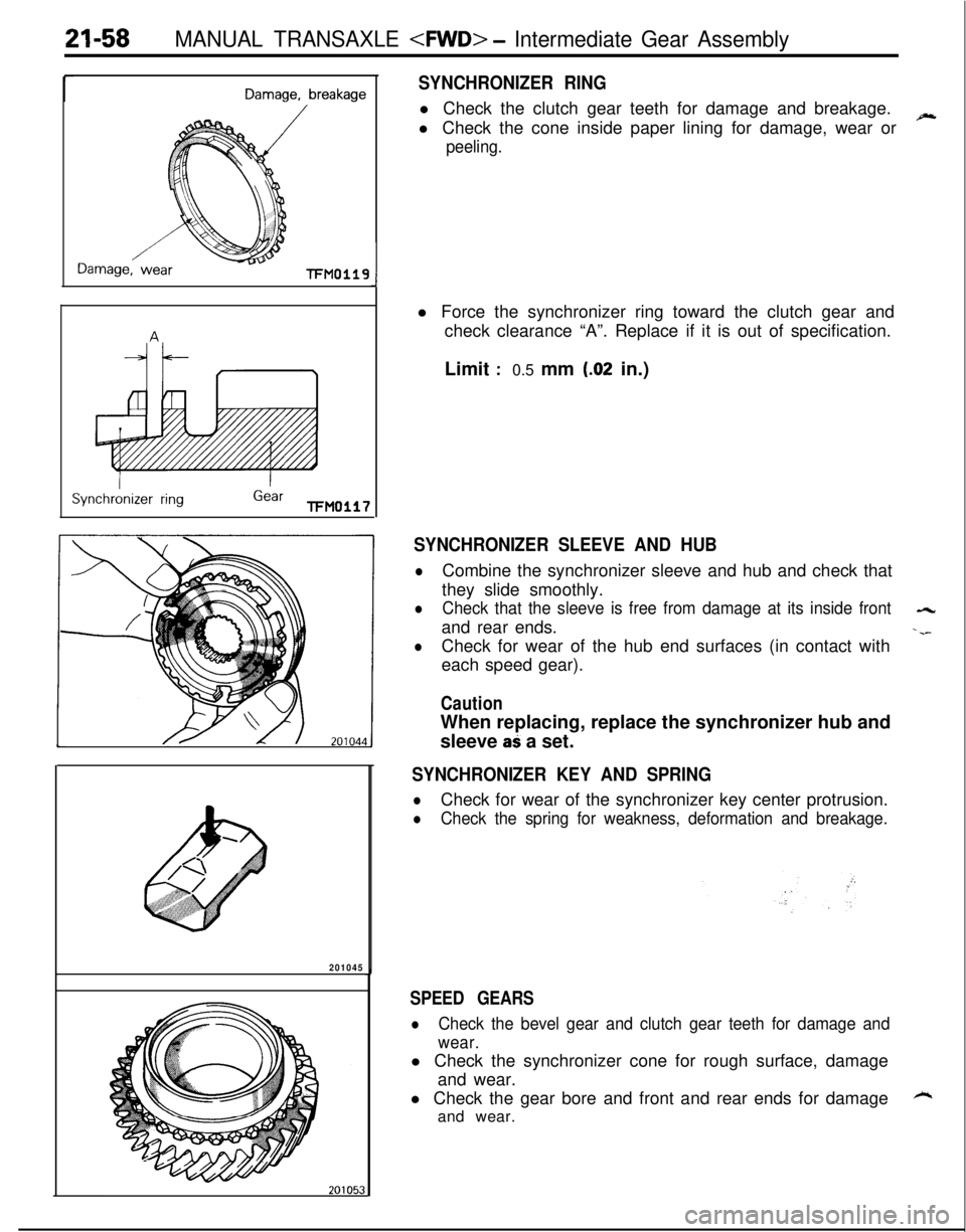
SYNCHRONIZER RINGl Check the clutch gear teeth for damage and breakage.
l Check the cone inside paper lining for damage, wear or
~
peeling.
J
201045l Force the synchronizer ring toward the clutch gear and
check clearance “A”. Replace if it is out of specification.
Limit
:0.5 mm (.02 in.)
SYNCHRONIZER SLEEVE AND HUB
lCombine the synchronizer sleeve and hub and check that
they slide smoothly.
lCheck that the sleeve is free from damage at its inside front-4rand rear ends.
-.--
lCheck for wear of the hub end surfaces (in contact with
each speed gear).
CautionWhen replacing, replace the synchronizer hub and
sleeve
aS a set.
SYNCHRONIZER KEY AND SPRING
lCheck for wear of the synchronizer key center protrusion.
lCheck the spring for weakness, deformation and breakage.
SPEED GEARS
lCheck the bevel gear and clutch gear teeth for damage and
wear.l Check the synchronizer cone for rough surface, damage
and wear.
l Check the gear bore and front and rear ends for damage
kand wear.
Page 753 of 1216
MANUAL TRANSAXLE
.-_
Front +Identi-fication
mark
210031
Springprotrusion
Key2010018
SERVICE POINTS OF REASSElViBLY
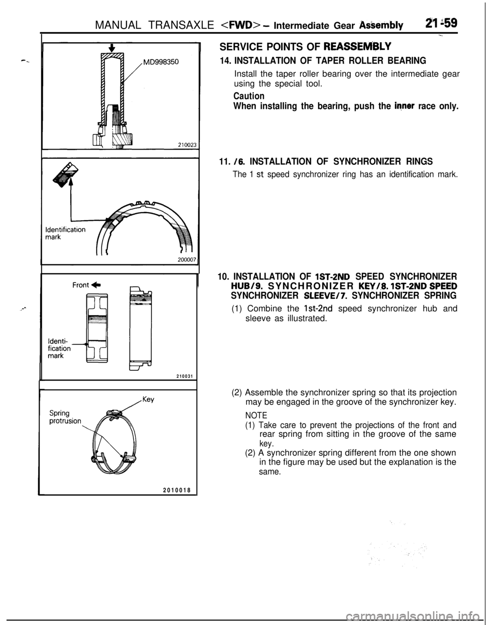
14. INSTALLATION OF TAPER ROLLER BEARINGInstall the taper roller bearing over the intermediate gear
using the special tool.
Caution
When installing the bearing, push the inner race only.
11. /6.
INSTALLATION OF SYNCHRONIZER RINGS
The 1 st speed synchronizer ring has an identification mark.
10. INSTALLATION OF lST-2ND SPEED SYNCHRONIZER
HUB/S. SYNCHRONIZER KEYi.8. IST-2ND SPEED
SYNCHRONIZER SLEEVE/7. SYNCHRONIZER SPRING(1) Combine the
lst-2nd speed synchronizer hub and
sleeve as illustrated.
(2) Assemble the synchronizer spring so that its projection
may be engaged in the groove of the synchronizer key.
NOTE
(1) Take care to prevent the projections of the front andrear spring from sitting in the groove of the same
key.(2) A synchronizer spring different from the one shown
in the figure may be used but the explanation is the
same.
Page 754 of 1216
21-60MANUAL TRANSAXLE
MD998350
/
1 st-2ndspeedsynchronizerassembly
201069
. MD998350
I
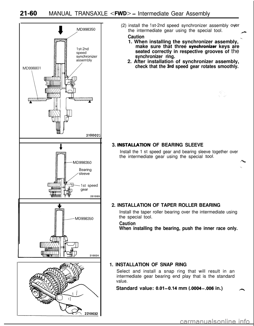
3210024(2) install the Ist-2nd speed synchronizer assembly
overthe intermediate gear using the special tool.
,-
Caution1. When installing the synchronizer assembly,
-‘make sure that three
synchronizer keys are
seated correctly in respective grooves of the
synchronizer ring.2. After installation of synchronizer assembly,
check that the 3rd speed gear rotates smoothly.
3. INSTALLATlON OF BEARING SLEEVE
Install the 1 st speed gear and bearing sleeve together overthe intermediate gear using the special
-tool.
r%
-.
2. INSTALLATION OF TAPER ROLLER BEARINGInstall the taper roller bearing over the intermediate using
the special tool.
Caution
When installing the bearing, push the inner race only.
1. INSTALLATION OF SNAP RINGSelect and install a snap ring that will result in an
intermediate gear bearing end play that is the standard
value.Standard value: 0.01-0.14 mm
(.0004-.OOS in.)h
Page 795 of 1216
MANUAL TRANSAXLE
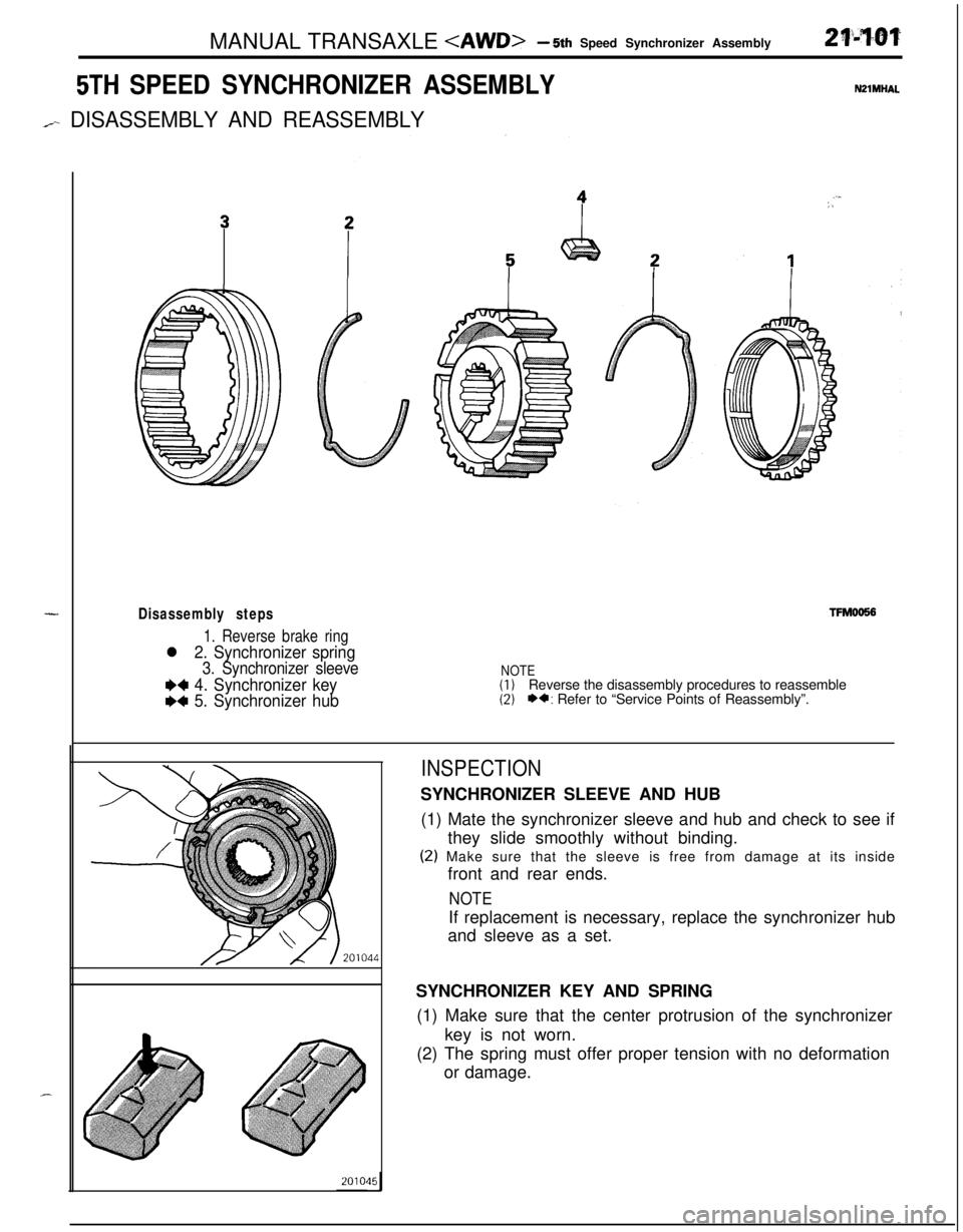
5TH SPEED SYNCHRONIZER ASSEMBLY
/-- DISASSEMBLY AND REASSEMBLY
-Disassembly steps
1. Reverse brake ring
l 2. Synchronizer spring
3. Synchronizer sleeve
W 4. Synchronizer key
I)+ 5. Synchronizer hub
WlMHAL
. . I:,
TFMOO!56
NOTE(1)Reverse the disassembly procedures to reassemble(2)*a: Refer to “Service Points of Reassembly”.
INSPECTIONSYNCHRONIZER SLEEVE AND HUB
(1) Mate the synchronizer sleeve and hub and check to see if
they slide smoothly without binding.
(2) Make sure that the sleeve is free from damage at its inside
front and rear ends.
NOTEIf replacement is necessary, replace the synchronizer hub
and sleeve as a set.
SYNCHRONIZER KEY AND SPRING
(1) Make sure that the center protrusion of the synchronizer
key is not worn.
(2) The spring must offer proper tension with no deformation
or damage.
Page 796 of 1216
21-102MANUAL TRANSAXLE
Oil groove
5thspeed +
$2
TFM0046
201001a,
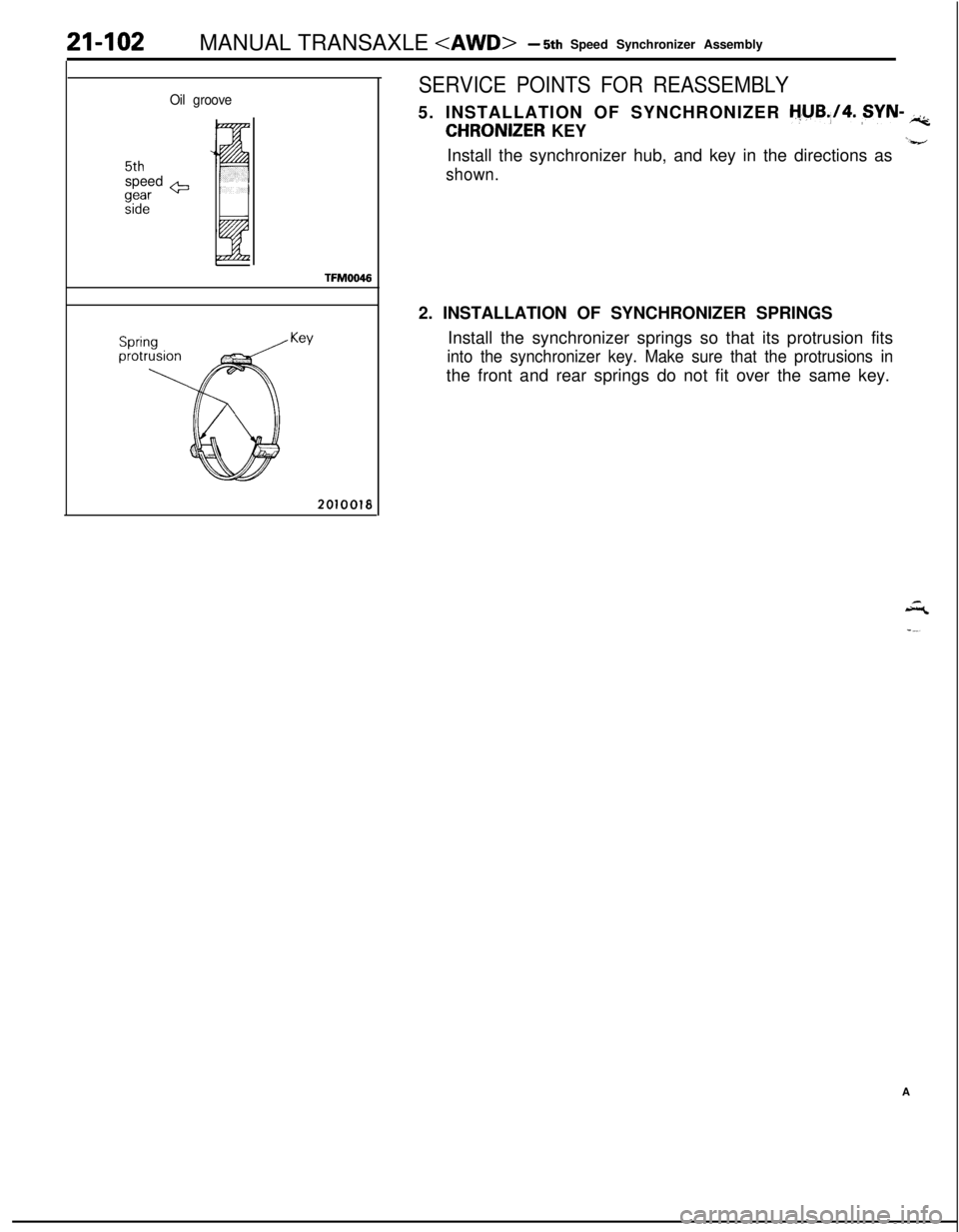
SERVICE POINTS FOR REASSEMBLY5. INSTALLATION OF SYNCHRONIZER
tjyB.,/4. ,SYN- iic;
CHRONIZER KEY‘-a-/Install the synchronizer hub, and key in the directions as
shown.2. INSTALLATION OF SYNCHRONIZER SPRINGS
Install the synchronizer springs so that its protrusion fits
into the synchronizer key. Make sure that the protrusions inthe front and rear springs do not fit over the same key.
A
Page 804 of 1216

21-I 10MANUAL TRANSAXLE
INTERMEDIATE GEAR ASSEMBLYNPlMJAR
DISASSEMBLY AND REASSEMBLY
j”r:
Disassembly steps
** 1. Snap ringl * l +2. Taper roller bearing
l * 3. Bearing sleeve
l *4. 1 st speed gear
5. Needle bearing
l a6. Synchronizer ringl +7. Synchronizer springl a8. 1 st-2nd speed synchronizer sleeve
l *9. Synchronizer keyw l a IO. 1 st-2nd speed synchronizer hub
l * II. Synchronizer ringa*12. 2nd speed gear
13. Needle bearing
l * l * 14. Taper roller bearing
15. Intermediate gearNOTE(I) Reverse the disassembly procedures to reassemble.Ah..(2)+*: Refer to “Service Points of Disassembly”.(3)l C: Refer to “Service Points of Reassembly”.(4)q : Non-reusable parts.
Page 806 of 1216
21-112MANUAL TRANSAXLE
201051
Damage, breakage
I
-FM0119Synchronizer ring
Gear FM0117
NEEDLE BEARING
lMate the needle bearing with the shaft or bearing sleeve
and gear, and check to see if rotation is smooth with no
++binding, noise, or play.
l Check the needle bearing cage for possible deformation.
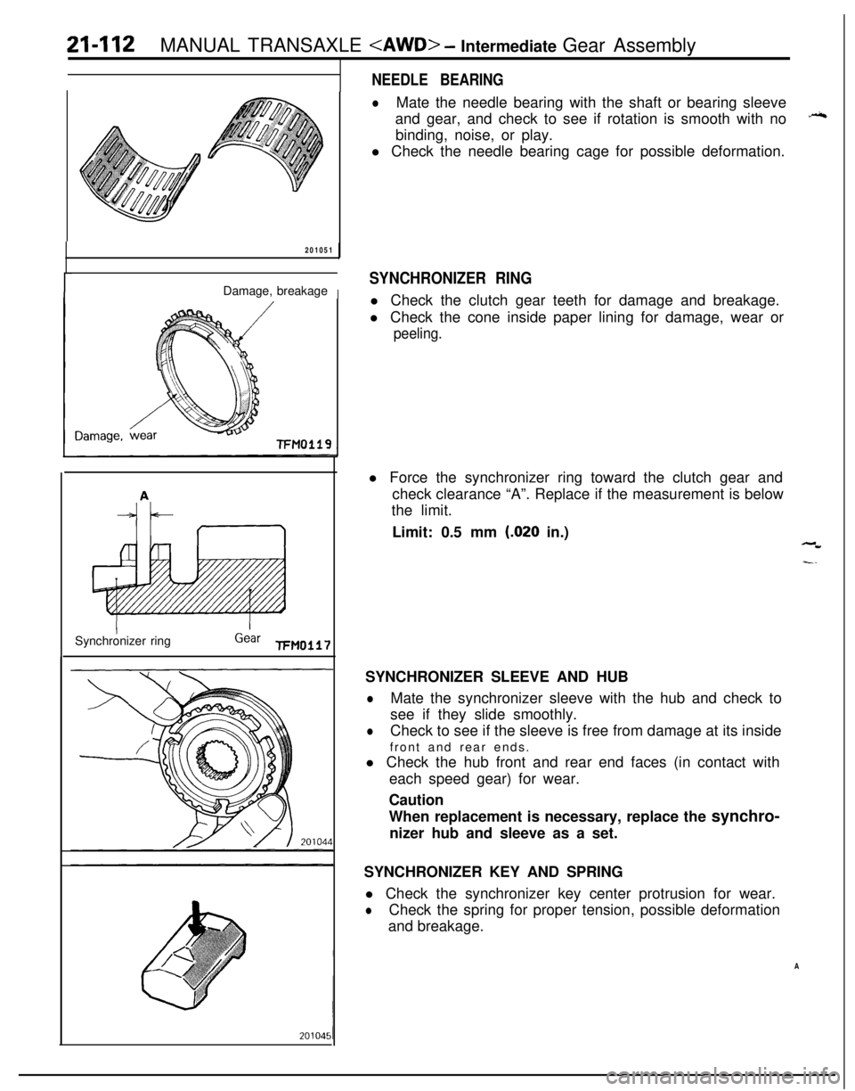
SYNCHRONIZER RINGl Check the clutch gear teeth for damage and breakage.
l Check the cone inside paper lining for damage, wear or
peeling.l Force the synchronizer ring toward the clutch gear and
check clearance “A”. Replace if the measurement is below
the limit.
Limit: 0.5 mm
(.020 in.),-W
I-.SYNCHRONIZER SLEEVE AND HUB
lMate the synchronizer sleeve with the hub and check to
see if they slide smoothly.
lCheck to see if the sleeve is free from damage at its inside
front and rear ends.
l Check the hub front and rear end faces (in contact with
each speed gear) for wear.
Caution
When replacement is necessary, replace the synchro-
nizer hub and sleeve as a set.
SYNCHRONIZER KEY AND SPRING
l Check the synchronizer key center protrusion for wear.
lCheck the spring for proper tension, possible deformation
and breakage.
A
Page 807 of 1216
-.
MANUAL TRANSAXLE
D99835021002:
r$J$ch housingc
prorruslon
Sprinprotrusion
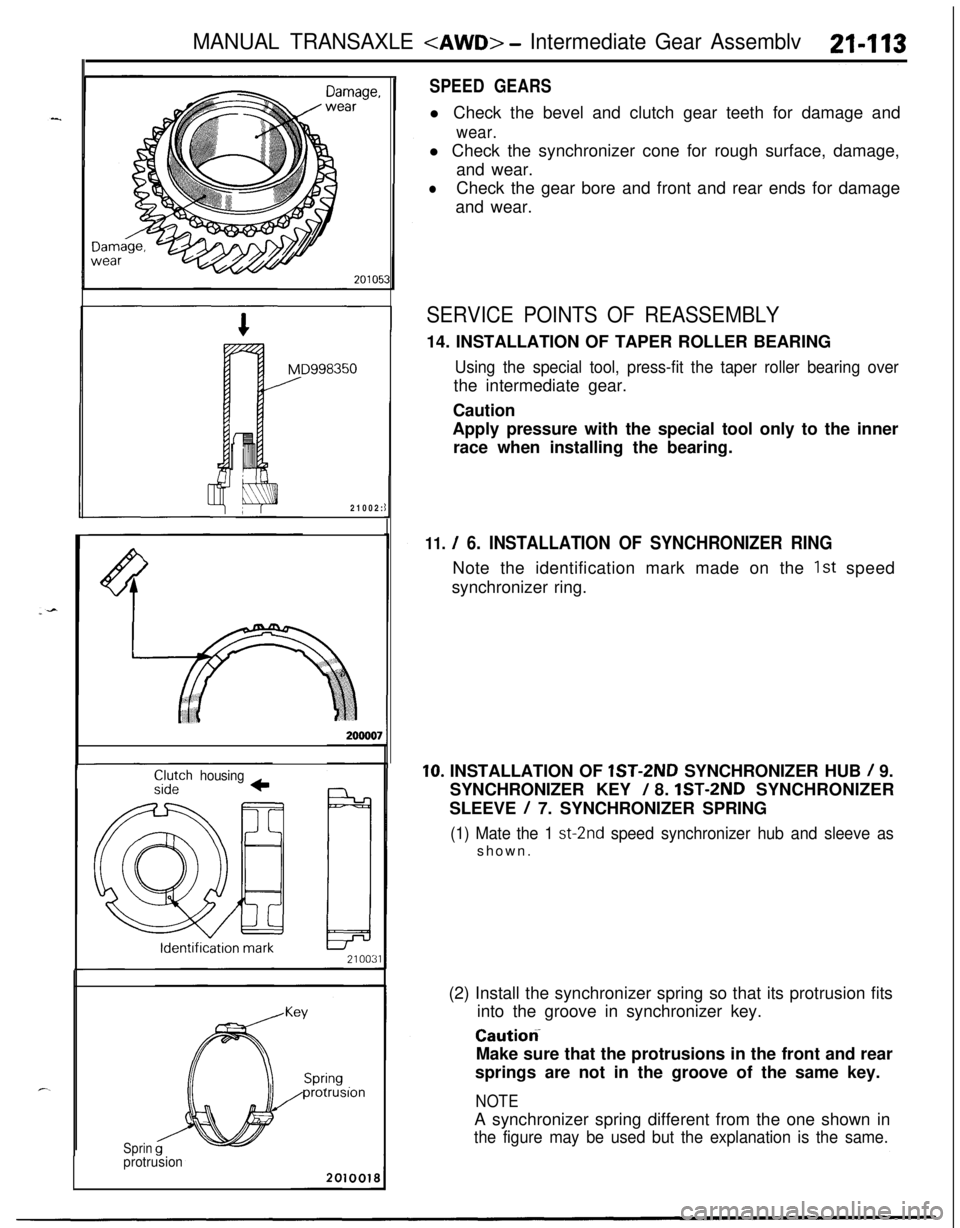
SPEED GEARSl Check the bevel and clutch gear teeth for damage and
wear.l Check the synchronizer cone for rough surface, damage,
and wear.
lCheck the gear bore and front and rear ends for damage
and wear.
SERVICE POINTS OF REASSEMBLY14. INSTALLATION OF TAPER ROLLER BEARING
Using the special tool, press-fit the taper roller bearing overthe intermediate gear.
Caution
Apply pressure with the special tool only to the inner
race when installing the bearing.
11. / 6. INSTALLATION OF SYNCHRONIZER RINGNote the identification mark made on the
1st speed
synchronizer ring.
10. INSTALLATION OF lST-2ND SYNCHRONIZER HUB / 9.
SYNCHRONIZER KEY
/ 8. lST-2ND SYNCHRONIZER
SLEEVE
/ 7. SYNCHRONIZER SPRING
(1) Mate the 1 st-2nd speed synchronizer hub and sleeve asshown.
(2) Install the synchronizer spring so that its protrusion fits
into the groove in synchronizer key.
Caution-Make sure that the protrusions in the front and rear
springs are not in the groove of the same key.
NOTEA synchronizer spring different from the one shown in
the figure may be used but the explanation is the same.