warning light MITSUBISHI ECLIPSE 1991 Owner's Manual
[x] Cancel search | Manufacturer: MITSUBISHI, Model Year: 1991, Model line: ECLIPSE, Model: MITSUBISHI ECLIPSE 1991Pages: 1216, PDF Size: 67.42 MB
Page 173 of 1216

BRAKES - Anti-lock Braking System Troubleshooting5-33
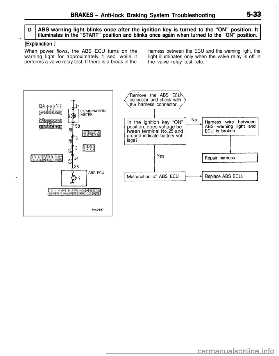
DABS warning light blinks once after the ignition key is turned to the “ON” position. It
illuminates in the “START” position and blinks once again when turned to the “ON” position.*-_
[Explanation ]When power flows, the ABS ECU turns on the
harness between the ECU and the warning light, thewarning light for approximately 1 sec. while itlight illuminates only when the valve relay is off in
performs a valve relay test. If there is a break in the
the valve relay test, etc.
Y
x %l4
9
4
n. 58
ABS ECU
14A0597
EC
4connector and check with
he harness connector. /\/
IIn the ignition key “ON”
position, does voltage be-
tween terminal
No.25 andground indicate battery vol-
tage?
Replace ABS ECU.I
Page 174 of 1216
![MITSUBISHI ECLIPSE 1991 Owners Manual 5-34BRAKES -Anti-lock Braking System Troubleshooting
E-lInput abnormality of wheel speed sensorI.
[Explanation][Hint]s”rThe ABS ECU detects breaks in the wheel speed
In addition to a broken wire/sho MITSUBISHI ECLIPSE 1991 Owners Manual 5-34BRAKES -Anti-lock Braking System Troubleshooting
E-lInput abnormality of wheel speed sensorI.
[Explanation][Hint]s”rThe ABS ECU detects breaks in the wheel speed
In addition to a broken wire/sho](/img/19/57104/w960_57104-173.png)
5-34BRAKES -Anti-lock Braking System Troubleshooting
E-lInput abnormality of wheel speed sensorI.
[Explanation][Hint]s”rThe ABS ECU detects breaks in the wheel speed
In addition to a broken wire/short circuit in the wheel--sensor wire. The warning light lights up if the wheel
speed sensor, also check whether the sensor gap isspeed sensor signal RL is not input (or shorttoo large, rotor teeth are missing, sensor- harness
circuited) or if its output is low when starting to drivewire is temporarily broken, or sensor harness and
or while driving.body connector are not properly inserted.
E-2Output abnormality of wheel speed sensor
[Explanation]The warning light lights up when there is an
abnormality (other than broken wire or short circuit)
in the wheel speed sensor output signal while
driving.
[Hinti
The following can be considered as the cause of thewheel speed sensor output abnormality.
l Distortion of rotor, teeth missing
lLow frequency noise interference when sensor
harness wire is broken
l Noise interference
in sensor signall When the sensor output signal is below the
standard value or when amplitude modulation is
over the standard value, using an oscilloscope tomeasure the wave shape of the wheel speed
sensor output signal is very effective.
l Loose wheel bearing
l Temporarily broken wire in sensor harness
l Sensor harness and body connector are not
properly inserted.
NOTE
If contact is poor, check the sensor cable by bendingand lightly stretching it.
SPEED SENSOR
FRONTREARP%(LEFT SIDE)
(RIGHT SIDE)(LEFT SIDE)(RIGHT SIDE),’
1
FRONT SIDE
SELF-DIAGNOSISCHECK CONNECTOR14AO608
Page 176 of 1216
![MITSUBISHI ECLIPSE 1991 Owners Manual 5-36BRAKES - Anti-lock Braking System Troubleshooting
E-3Abnormality of G sensor circuit
[Explanation]The ABS ECU turns on the warning light in the
following cases.
lOFF trouble turning G sensor OFF ( MITSUBISHI ECLIPSE 1991 Owners Manual 5-36BRAKES - Anti-lock Braking System Troubleshooting
E-3Abnormality of G sensor circuit
[Explanation]The ABS ECU turns on the warning light in the
following cases.
lOFF trouble turning G sensor OFF (](/img/19/57104/w960_57104-175.png)
5-36BRAKES - Anti-lock Braking System Troubleshooting
E-3Abnormality of G sensor circuit
[Explanation]The ABS ECU turns on the warning light in the
following cases.
lOFF trouble turning G sensor OFF (It is judged
that the
G sensor continues to be OFF for more
than approximately 13 seconds except when the
lWhen there is a broken wire or short circuit in
the harness for the
G sensor system.
PlUN; F;SIBLEIGNITIONSWITCH (IG2)J/B
G-SENSOR
E-lABSECU
14AO609
Is G sensor normal? (ReferNoto
P.5-86.)Replace G sensor.
I YesWith the ignition key “ON”
_ No m The harness between the
does the voltage betweenG sensor and the ABS
terminal No.6 and groundECU is broken.
indicate battery voltage?
IG sensor circuit is normal.I
Page 177 of 1216
![MITSUBISHI ECLIPSE 1991 Owners Manual BRAKES - Anti-lock Braking System Troubleshooting5-37
E-4Abnormality of stop light switch circuitI
- [Explanation][Hint]The ABS ECU turns on the warning light in theIf the stop light operates normal, MITSUBISHI ECLIPSE 1991 Owners Manual BRAKES - Anti-lock Braking System Troubleshooting5-37
E-4Abnormality of stop light switch circuitI
- [Explanation][Hint]The ABS ECU turns on the warning light in theIf the stop light operates normal,](/img/19/57104/w960_57104-176.png)
BRAKES - Anti-lock Braking System Troubleshooting5-37
E-4Abnormality of stop light switch circuitI
- [Explanation][Hint]The ABS ECU turns on the warning light in theIf the stop light operates normal, the ABS harness
following cases.
wire for the stop light switch input circuit to the ECU
lStop light switch may remain on for more thanis broken or there is a malfunction in the ABS ECU.
15 minutes without the ABS functions.
lThe harness wire for the stop light switch may
be open.
AUTO-CRUISE
STOP
--I0.85-G
’LIGHT
w
STOPLIGHTSWITCHABSECURESIS-
TOR
14AO610
Do the stop lights light up _ No c Check the stop light re-and go out normally?lated circuit and repair
problem spots.
Yes
isconnect the ABS ECconnector and inspect at
the harness side
connec-
tor.When the brake pedal is
NoHarness wire between
pressed forcefully, does the
* stop light switch and ABS
voltage between connectorECU is broken.
terminal No. 29 and ground
indicate battery voltage?
c
Repair harness.
Yes.
;gSJ;ght switch circuit is
Page 178 of 1216
![MITSUBISHI ECLIPSE 1991 Owners Manual 5-38BRAKES - Anti-lock Braking System Troubleshooting
E-5Abnormality of solenoid valve drive circuit
[Explanation]*>The ABS ECU normally monitors the solenoid valve
when turned OFF, the ECU determines MITSUBISHI ECLIPSE 1991 Owners Manual 5-38BRAKES - Anti-lock Braking System Troubleshooting
E-5Abnormality of solenoid valve drive circuit
[Explanation]*>The ABS ECU normally monitors the solenoid valve
when turned OFF, the ECU determines](/img/19/57104/w960_57104-177.png)
5-38BRAKES - Anti-lock Braking System Troubleshooting
E-5Abnormality of solenoid valve drive circuit
[Explanation]*>The ABS ECU normally monitors the solenoid valve
when turned OFF, the ECU determines the solenoid%’ -’drive circuit.coil wire is broken/short circuited or the harness is
If no current flows in the solenoid even if the ECUbroken/short circuited and then the warning light
turns the solenoid ON or if it continues to flow evenlights up.
IGNITIONSWITCH(IGI)
7JIB------_-_tor and check with the
side connector.
Connect HU
1OP connec-
disconnect ECU con-
>Is the solenoid valve resis-
tance value within the range
of the standard values when
measured at the ECU con-
nector?Standard value:
3.0-3.2 Q
Yes1
II
I
Solenoid valve drive circuit isnormal.I
NoReplace HU.I
NoIs the resistance value for
the solenoid valve within the
range ofthe standard
values?Standard value:
3.0-3.2 Q, IYes ,
1
JThe harness wire for the
solenoidvalvecircuit
whose resistance value is
outside the range of the
standard value is broken
or short circuited.,-‘he-
-Repair
Page 179 of 1216
![MITSUBISHI ECLIPSE 1991 Owners Manual BRAKES - Anti-lock Braking System Troubleshooting5-39
E-6Abnormality of valve relay drive circuitI
j-a [Explanation]When the ignition switch is turned ON, the ABSnormal. In addition, normally it monit MITSUBISHI ECLIPSE 1991 Owners Manual BRAKES - Anti-lock Braking System Troubleshooting5-39
E-6Abnormality of valve relay drive circuitI
j-a [Explanation]When the ignition switch is turned ON, the ABSnormal. In addition, normally it monit](/img/19/57104/w960_57104-178.png)
BRAKES - Anti-lock Braking System Troubleshooting5-39
E-6Abnormality of valve relay drive circuitI
j-a [Explanation]When the ignition switch is turned ON, the ABSnormal. In addition, normally it monitors whether or
ECU switches the valve relay OFF and ON for annot there is power in the valve power monitor line
initial check, compares the voltage of the signal tosince the valve relay is normally ON. Then, if the
the valve relay and valve power monitor line voltagesupply of power to the valve power monitor line is
to check whether the valve relay operation is
interrupted, the warning light illuminates.
IGNITIONMAIN FUSIBLESWITCHLINK @W-31)When the valve relay is
checked, are the followingconditions found?No.85-No.86:resistancevalue 60-120 Q
No.30-No.87a: continuityNo.30-No.87: No continui-
When battery voltage is ap-plied between terminals
No.86 and No. 85 grounded.
No. 30-No. 87: continuity
No.
30-No. 87a: no continui-
tyremove the HU connec-
NoValve relay malfunction
Replace valve relay.
IConnect the HU
remove the ECU con-
I Yes
IValve relay drive circuit isnormal.I
Page 180 of 1216
![MITSUBISHI ECLIPSE 1991 Owners Manual 5-40BRAKES - Anti-lock Braking System Troubleshooting
E-7Abnormality of motor drive circuit
[Explanation]The ABS ECU illuminates the warning light for the
motor relay and motor in the following cases. MITSUBISHI ECLIPSE 1991 Owners Manual 5-40BRAKES - Anti-lock Braking System Troubleshooting
E-7Abnormality of motor drive circuit
[Explanation]The ABS ECU illuminates the warning light for the
motor relay and motor in the following cases.](/img/19/57104/w960_57104-179.png)
5-40BRAKES - Anti-lock Braking System Troubleshooting
E-7Abnormality of motor drive circuit
[Explanation]The ABS ECU illuminates the warning light for the
motor relay and motor in the following cases.
l When the motor relay does not function
lWhen there is trouble with the motor itself and it
does not revolve
[Hint]If there is motor operation noise when wheel speed
exceeds
Gkm/h (4mph) when starting up after the
engine is started, there is a broken or short circuitedmotor monitor wire.
lWhen the motor ground line is disconnected andthe motor does not revolve
l When the motor continues to revolve
Does the motor make a
YesBroken wire or short cir-noise when wheel speed
-cuit in motor monitor line
exceeds 6 km/h (4 mph)?
b
NoRepair the harness between HU and ECU.
emove the motor rela
ABS ECU
14A0105
Remove the motor relav and
check resistance values.
No.
85-No. 86:resistancevalue 30-60 QNo.30-No.87: no continui-
ty
Battery voltage is applied on
terminals No. 86 and No. 85
grounded
No. 30-No. 87: continuity
Yes
q Motor relay malfunction 1
Replace motor relay.I
Is pump motor ground con-netted normally?Connect ground wire.I
b
Does voltage between bodyNo
connector terminal 51 andIBroken wire in pumpmotor power circuit
ground indicate battery vol-
tage?1Repair the harness.
YesIs resistance between body
- No L Malfunction of harness
connector terminal No. 2 andbetween HU and ECU
No.26 30-60 ohms?b
YesRepair harness.
Motor drive circuit is normal.
Page 192 of 1216

5-52BRAKES - Service Adjustment Procedures
16LO312lOWOO
(1) Remove the ABS power relay from the ABS control unit q
bracket.-/ABS POWER RELAY CHECK
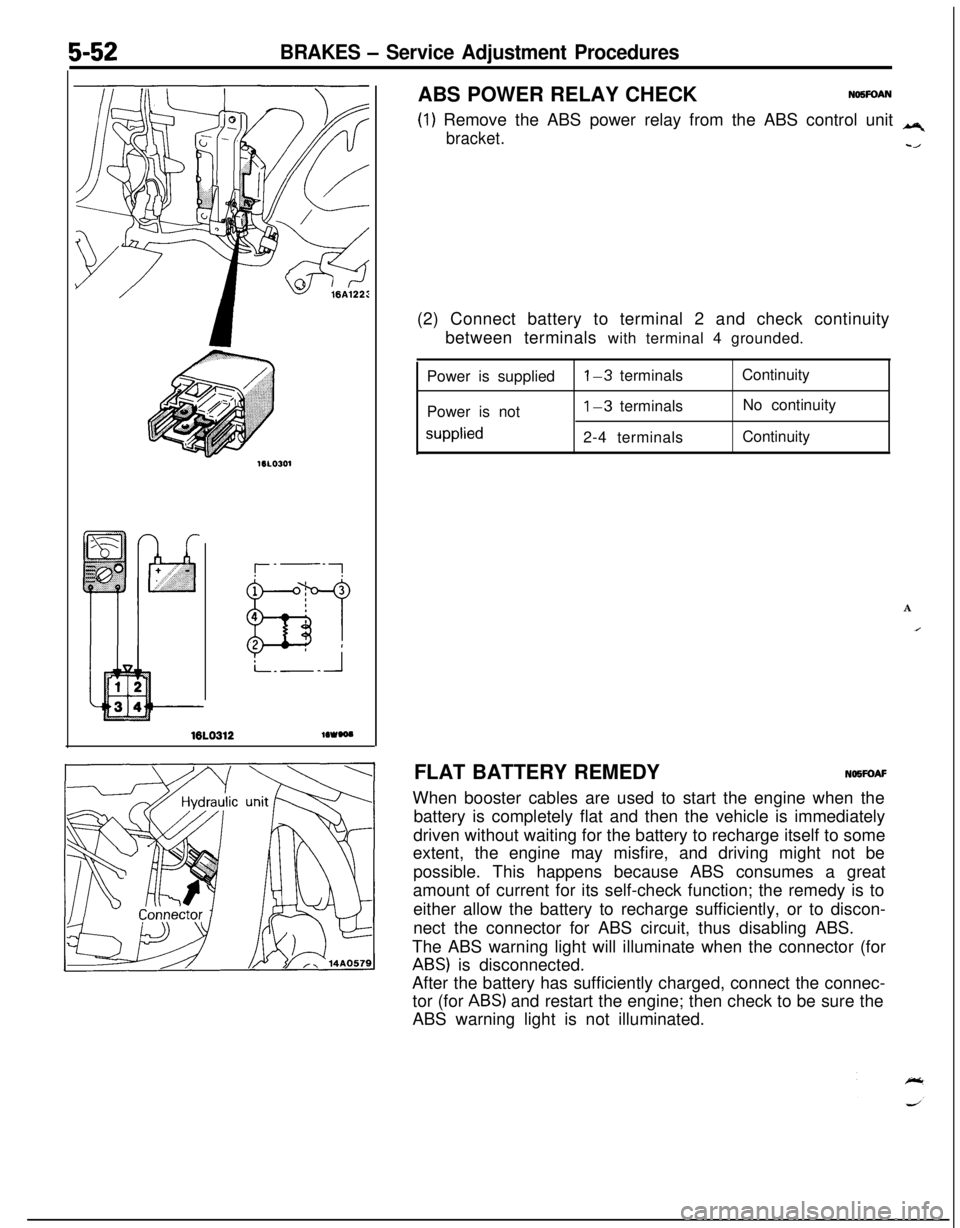
NO5FOAN(2) Connect battery to terminal 2 and check continuity
between terminals with terminal 4 grounded.
Power is supplied
Power is not
supplied
l-3 terminals
1-3 terminals
2-4 terminalsContinuity
No continuity
Continuity
A
IFLAT BATTERY REMEDYNOWOAF
When booster cables are used to start the engine when the
battery is completely flat and then the vehicle is immediately
driven without waiting for the battery to recharge itself to some
extent, the engine may misfire, and driving might not be
possible. This happens because ABS consumes a great
amount of current for its self-check function; the remedy is to
either allow the battery to recharge sufficiently, or to discon-
nect the connector for ABS circuit, thus disabling ABS.
The ABS warning light will illuminate when the connector (for
ABS) is disconnected.
After the battery has sufficiently charged, connect the connec-
tor (for
ABS) and restart the engine; then check to be sure the
ABS warning light is not illuminated.
Page 877 of 1216

AUTOMATIC TRANSAXLE - Troubleshooting214%3
TRANSAXLE CONTROL UNIT
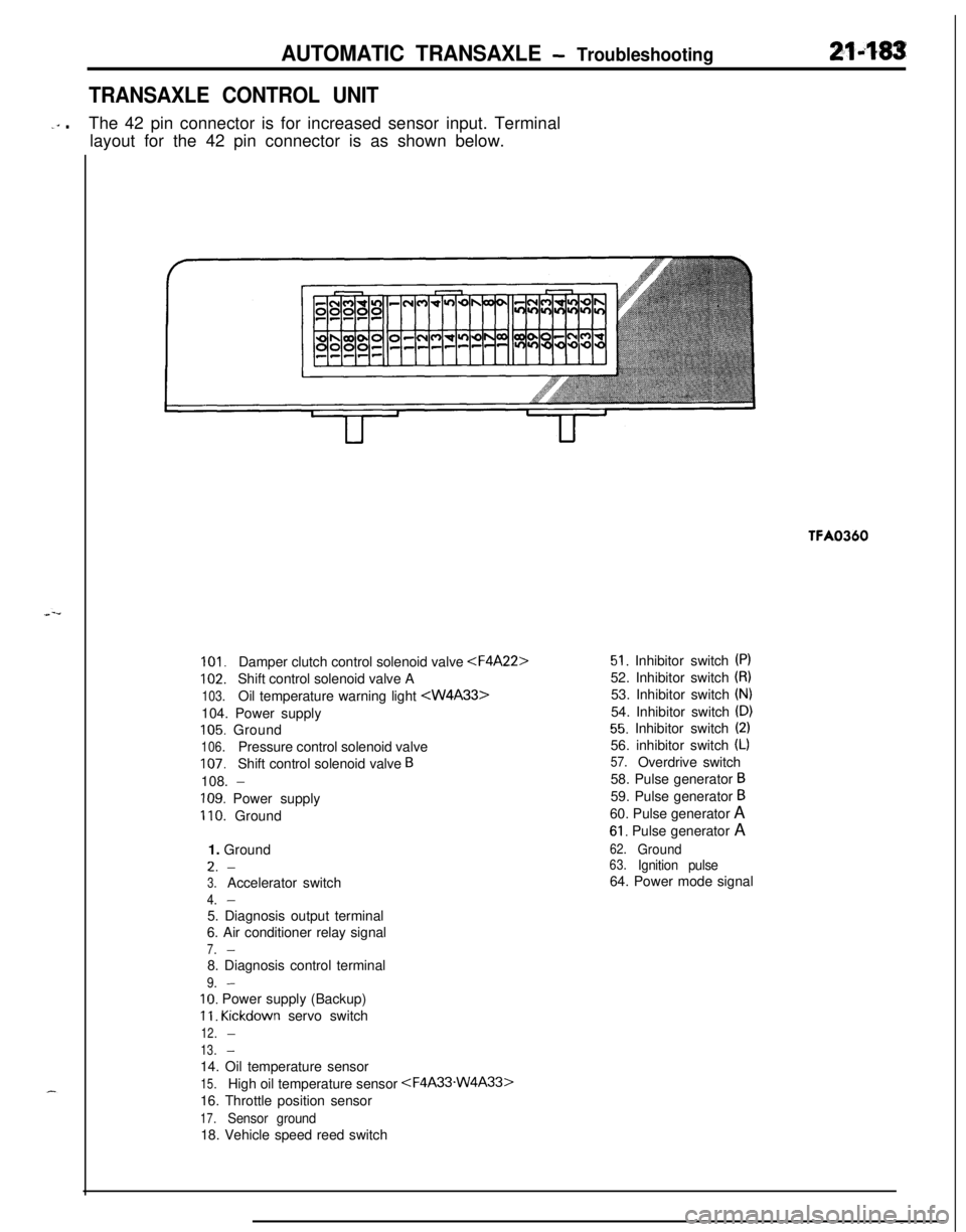
-‘” .The 42 pin connector is for increased sensor input. Terminal
layout for the 42 pin connector is as shown below.TFA0360
101.Damper clutch control solenoid valve
102.Shift control solenoid valve A
103.Oil temperature warning light
105. Ground
106.Pressure control solenoid valve
107.Shift control solenoid valve B108.
-
109. Power supply
110. Ground
1. GroundL.
-
3.Accelerator switch
4.-5. Diagnosis output terminal
6. Air conditioner relay signal
7.-8. Diagnosis control terminal
9.-
IO. Power supply (Backup)
11. Kickdown servo switch
12.-
13.-14. Oil temperature sensor
15.High oil temperature sensor
16. Throttle position sensor
17.Sensor ground18. Vehicle speed reed switch
51. Inhibitor switch (PI52. Inhibitor switch
(8)53. Inhibitor switch
(N)54. Inhibitor switch
(D)
55. Inhibitor switch (2)56. inhibitor switch
(L)
57.Overdrive switch
58. Pulse generator
B59. Pulse generator
B60. Pulse generator A
61. Pulse generator A
62.Ground63.Ignition pulse64. Power mode signal
Page 1060 of 1216

23-16BODY - Troubleshooting
OPERATION
Key-reminder warning0 Battery voltage is always supplied, through sub
fusible link No.
@, to the key-reminder switch.0 When the driver’s seat door is opened while the
ignition key is still in the key cylinder, the door
switch is switched ON, electricity flows to sub
fusible link No.
0, the key-reminder switch, the
buzzer, the door switch, and ground, and the
buzzer sounds.
Seat belt warning0 Battery voltage is applied, through fuse No.
0,to the seat belt timer when the ignition key is at
the “ON” position.0 Electricity flows to sub fusible link No. @, the
key-reminder switch, the seat belt warning light,
the seat belt timer, and ground, and the seat beltwarning light illuminates for approx. 6 seconds.0
If the driver does not buckle the seat belt, the seatbelt switch is switched ON, electricity flows to
sub fusible link No. @, the key-reminder switch,the buzzer, the seat belt switch, the seat belt
warning timer, and ground, and the buzzer
sounds for approx. 6 seconds.0 When the driver buckles the seat belt, the seat
belt switch is switched OFF and the buzzer stops.
TROUBLESHOOTING HINTS
Key-reminder warningThe key-reminder warning doesn’t sound.
(1) The seat belt warning function is OK.
l Check the door switch.
(2) The seat belt warning also doesn’t function.0 Check the buzzer.
Seat belt warning1. The seat belt warning doesn’t function.
(1) The seat belt warning light illuminates.0 Check the seat belt switch.
(2) The seat belt warning light also does not
function (but the key-reminder warning
functions normally. 10 Check the seat belt timer.
(3) The seat belt warning light also does not
function (and the key-reminder warning also
does not function).0 Check the key-reminder switch.
2.The buzzer doesn’t stop even though the driver’s
seat belt has been buckled.0 Check the seat belt switch.
3.The seat belt warning light doesn’t illuminate (but
the buzzer sounds).l Check the light bulb.
’ I